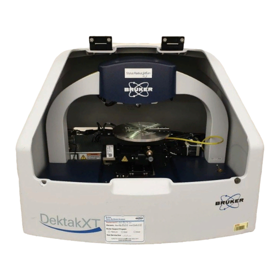
Bruker Dektak XT Operation Manual
2d profilometer
Hide thumbs
Also See for Dektak XT:
- User manual (83 pages) ,
- Installation and maintenance manual (32 pages) ,
- Manual (7 pages)
Advertisement
Dektak XT 2D Profilometer Operation Manual
The Dektak XT is a 2D contact profilometer used for step height, pitch and surface roughness
measurements. Vision 64 application software controls the system data collection and analysis.
Specifications
•
Stylus Contact Profilometry
Two-dimensional surface profile measurements
•
Stylus Force 1 to 15mg
•
12.5um diameter tip
•
•
Sample X/Y Stage Manual 100mm (4 in.) X/Y, manual leveling
•
Software Vision 64 Operation and Analysis Software
Scan Length Range 55mm (2in.)
•
Data Points Per Scan 120,000 maximum
•
•
Max. Sample Thickness 50mm (1.95in.)
•
Max. Wafer Size 200mm (8in.)
Step Height Repeatability <5Å, 1sigma on 0.1μm step
•
Vertical Range 1mm (0.039in.)
•
Vertical Resolution 1Å max. (@ 6.55_m range
•
pg. 1, Revision 6/2017
Advertisement
Table of Contents

Summary of Contents for Bruker Dektak XT
-
Page 1: Specifications
Dektak XT 2D Profilometer Operation Manual The Dektak XT is a 2D contact profilometer used for step height, pitch and surface roughness measurements. Vision 64 application software controls the system data collection and analysis. Specifications • Stylus Contact Profilometry Two-dimensional surface profile measurements •... - Page 2 Loading a Sample Verify the system has been enabled on Badger. Read all Shutdown, Problems or Comments related to the tool. Make sure the system is ON. If not, press white power on button; button should light up. If the Vision 64 software is not displayed, open the software. If not click on the software icon. The tower assembly will move to its upper limit, the stylus in the Tower Up position and the white sample light will come on.
- Page 3 should touch down. During the measurement the stylus will move in the +Y-direction (the stage will move in the –Y-direction). 13. The sliders at the bottom of the Live Video panel control the magnification and brightness of the image. Unloading a Sample and Shutdown 1.
- Page 4 Creating a Measurement Recipe The Measurement Setup window is used to define the measurement parameters. Scan Type: This system is only configured with the Stand Scan option. Range: Defines the height resolution of the data for the scan. Note the larger the step height range selected, the lower the resolution of the measurement.
-
Page 5: Making The Measurement
Resolution: The resolution of the scan is not an open field, it is calculated from the Scan Length and the scan Duration. 10. Sample: Indicates the number of data points that the system will collect during the measurement. 11. Speed: Is the calculated scan speed in units of um/s from the inputted scan Length and Duration. - Page 6 4. The scan direction moves from the center of the cross-hairs towards the top of the displayed image. Click on the Measurement icon to initiate the data collection. The real time Data Acquisition window open, where you can track the data collection. Once the scan has completed the Data Analysis window automatically opens.
- Page 7 5. To software level the results, click on Terms Removal (F-Operator) under the Analysis Toolbox window. 6. On the data window, right click and select Two-Point Linear Fit from the Data Leveling Setting pop-up menu. The data will be replotted using the R and M cursor intercepts at zero. pg.


Need help?
Do you have a question about the Dektak XT and is the answer not in the manual?
Questions and answers