
Related Manuals for Atlona Omega AT-OME-MS42


Summary of Contents for Atlona Omega AT-OME-MS42
- Page 1 4K / UHD Three-Input Switcher for HDMI and USB-C with HDBaseT and HDMI Outputs ™ Atlona Manuals AT-OME-MS42 Switchers...
- Page 2 Version Information Version Release Date Notes Sep 2019 Initial release AT-OME-MS42...
- Page 3 Welcome to Atlona! Thank you for purchasing this Atlona product. We hope you enjoy it and will take a extra few moments to register your new purchase. Registration only takes a few minutes and protects this product against theft or loss. In addition, you will receive notifications of product updates and firmware.
- Page 4 Atlona requires that products returned are properly packed, preferably in the original carton, for shipping. Cartons not bearing a return authorization or case number will be refused. Atlona, at its sole discretion, reserves the right to reject any products received without advanced authorization. Authorizations can be requested by calling 1-877-536-3976 (US toll free) or 1-408- 962-0515 (US/international) or via Atlona’s website at atlona.com.
- Page 5 Damage, deterioration or malfunction resulting from the installation or removal of this product from any installation, any unauthorized tampering with this product, any repairs attempted by anyone unauthorized by Atlona to make such repairs, or any other cause which does not relate directly to a defect in materials and/or workmanship of this product.
- Page 6 The information bubble is intended to alert the user to helpful or optional opera- product. tional instructions in the literature accompanying the product. 11. Only use attachments/accessories specified by Atlona. 1. Read these instructions. 12. To reduce the risk of electric shock and/or damage 2. Keep these instructions.
-
Page 7: Table Of Contents
Table of Contents Introduction Features Package Contents Panel Description Front Panel Rear Panel Installation Audio Connection Instructions Connection Diagram IP Configuration Switching the IP Mode Using the Front Panel Setting the IP Address using the Web Server Displaying the IP Address Device Operation LED Indicators Switching Modes... - Page 8 Table of Contents Configuration and Management Interfaces Introduction to the Web Server Info Page A/V Settings Page Display Page RS-232 Page EDID Page USB Page Time Page Config Page System Page Solution Setup and Configuration Guide Display Control CEC Control Using RS-232 Using IP Pass-through mode...
-
Page 9: Introduction
Introduction The Atlona AT-OME-MS42 is a 4x2 matrix switcher with HDMI, USB-C, and DisplayPort inputs, plus HDMI and HDBaseT outputs. Part of the Omega™ Series of integration products for modern AV communications and collaboration, the OME-MS42 is HDCP 2.2 compliant and features HDBaseT extension for video up to 4K/60 4:2:0, plus embedded audio, control, Ethernet, and USB over distances up to 330 feet (100 meters). -
Page 10: Panel Description
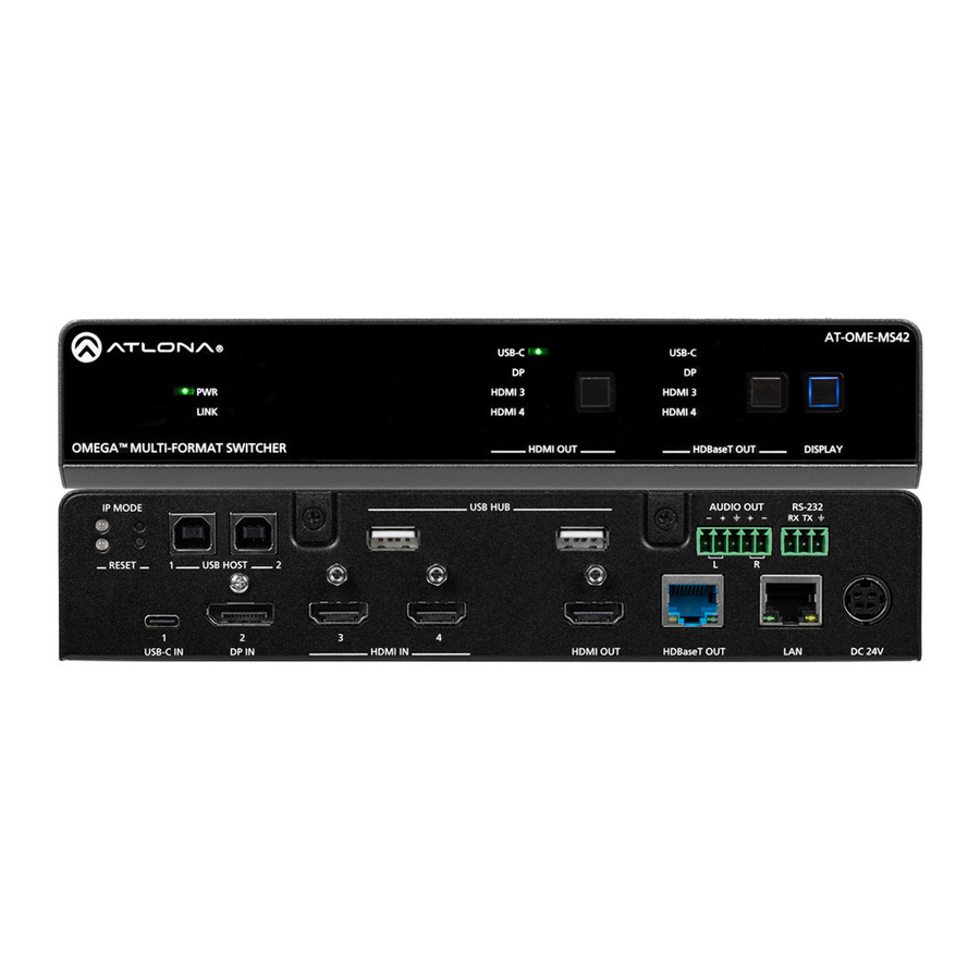
Panel Description Front Panel AT-OME-MS42 USB-C USB-C HDMI 3 HDMI 3 LINK HDMI 4 HDMI 4 HDMI OUT HDBaseT OUT OMEGA MULTI-FOMAT SWITCHER USB HUB RS-232 AUDIO OUT IP MODE RX TX RESET USB HOST HDMI OUT: Input Selection USB-C IN DP IN HDMI IN HDMI OUT... -
Page 11: Rear Panel
AT-OME-MS42 USB-C USB-C Panel Description HDMI 3 HDMI 3 LINK HDMI 4 HDMI 4 Rear Panel HDMI OUT HDBaseT OUT OMEGA MULTI-FOMAT SWITCHER USB HUB RS-232 AUDIO OUT IP MODE RX TX RESET USB HOST USB-C IN DP IN HDMI IN HDMI OUT HDBaseT OUT DC 24V... -
Page 12: Installation
Installation Audio The AUDIO OUT connector on the AT-OME-MS42 provides a separate output for balanced audio using XLR connectors. Use the included 5-pin captive-screw terminal block. Balanced audio connections use two signal wires and a ground to minimize interference in audio signals. Unbalanced output audio is not recommended and may require additional equipment. -
Page 13: Connection Instructions
Installation Connection Instructions 1. Connect a high-quality USB-C cable from a source to the USB-C (1) port. 2. Connect a DisplayPort cable from a source to the DP IN (2) port. 3. Connect up to two UHD/HD sources, using HDMI cables, to the HDMI IN (3) and HDMI IN (4) ports. 4. -
Page 14: Connection Diagram
Installation Connection Diagram AT-VGW-250 Network Switch AT-VTP-800 Laptop Laptop S4 2 E- M AT-HDVS-CAM -O M -O M TE ST Laptop M AT M UL AT-OME-EX-RX AT-OME-MS42 Speaker / Mic Display AT-OME-MS42... -
Page 15: Ip Configuration
Installation IP Configuration The AT-OME-MS42 is shipped with DHCP enabled. Once connected to a network, the DHCP server (if available), will automatically assign an IP address to the unit. If the AT-OME-MS42 is unable to detect a DHCP server within 15 seconds, then the unit will use a self-assigned IP address within the range of 169.254.xxx.xxx. -
Page 16: Device Operation
Device Operation LED Indicators The LED indicators on both the front and rear of the unit provide basic information on the current status of the AT- OME-MS42. Description Solid green • Unit is powered using the included 24 V DC power supply. •... -
Page 17: Switching Modes
Device Operation Switching Modes The AT-OME-MS42 features three switching modes: Mirrored, Matrix Mode, and Matrix Mode with static route. Each of these modes will be covered in the following section. Switching modes can be configured using the built-in web server. Mirrored Mode This is the default mode. -
Page 18: Matrix Mode
Device Operation Matrix Mode This mode allows the AT-OME-MS42 to independently switch between any input to any output. Auto-switching is disabled in Matrix Mode. 1. Login to the web server. Refer to Introduction to the Web Server (page 51) for more information. 2. - Page 19 Device Operation 5. Click the Matrix Mode HDMI Source drop-down list and select the input to be routed to the HDMI OUT port. 6. Click the Matrix Mode HDBaseT Source drop-down list and select the input to be routed to the HDBaseT OUT port.
-
Page 20: Matrix Mode W/ Static Route
Device Operation Matrix Mode w/ Static Route This mode is desirable when integrating the AT-OME-MS42 with a video conference system. In this mode, both static input and output routing are specified. Auto-Switching (page 22) must be enabled. However, the specified static input will be removed from the auto-switching pool. - Page 21 Device Operation 5. Click the Matrix Mode Static Source drop-down to select the source that will be assigned as a “static” source. This source will be routed to the output selected in the Matrix Mode Static Output drop-down list. In this example, the source connected to the DisplayPort input (DP IN), will be output to the HDMI OUT port. The DP IN port is the static source and the HDMI OUT port is the static output.
-
Page 22: Auto-Switching
Device Operation Auto-Switching The AT-OME-MS42 provides auto-switching capability, which is enabled by default. This feature will automatically switch the input to the most recently-connected source. If a source is disconnected, then the input will automatically be switched to the previously-connected source. If no sources are found, the AT-OME-MS42 will initiate a five- minute countdown timer. -
Page 23: Setting The Fallback Input
Device Operation Setting the Fallback Input The default fallback port is set to Previous. This means if multiple sources are connected, then disconnected, the AT-OME-MS42 will automatically return to last-connected port. If desired, the fallback port can be set to another input. -
Page 24: Scaler Pass-Through
Device Operation Scaler Pass-Through Click this toggle switch to enable or disable the scaler pass-through feature. When set to the ON position, 4K content will be down-scaled to 1080p. When set to the OFF position, the output resolution / timing will be the same as the input source. -
Page 25: Notes On Scaling
Device Operation Notes on Scaling The following section provides important information about how the AT-OME-MS42 processes 4K (UHD) video signals. • The HDMI OUTPUT port supports up to 4K @ 60 Hz, 12-bit, with HDR. • If the source is 4K, and the HDMI OUTPUT port is connected to a 1080p (not 4K-capable) display, then the output will be down-scaled as follows: Input Output... -
Page 26: Audio Management
Device Operation Audio Management The AT-OME-MS42 provides control over audio muting on HDMI OUT, HDBaseT OUT, and ANALOG OUT outputs. Audio Output Muting 1. Login to the web server. Refer to Introduction to the Web Server (page 51). 2. Click A/V Settings in the menu bar. 3. -
Page 27: Hdcp Content
Device Operation HDCP Content Normally, if a source is transmitting HDCP content to a display that is not HDCP-compatible, then the resulting image on the display can be “snow”, image flickering, or no picture. For example, in the illustration below, a laptop source is connected to the AT-OME-MS42. -
Page 28: Edid Management
Device Operation EDID Management Before a source can send picture and sound to a display device, the source reads the EDID (Extended Display Identification Data) stored in the display. The EDID contains information about what type of video and audio formats are supported by the display. -
Page 29: Edid Presets
Device Operation EDID Presets The AT-OME-MS42 provides the option of selecting a preset EDID. The following presets are available. For information on Memory_1, Memory_2, and Memory_3 settings, refer to Storing EDID Data (page 30). IMPORTANT: If problems are encountered when using an EDID preset, try using the default setting of Connected Display. -
Page 30: Storing Edid Data
Device Operation Storing EDID Data The AT-OME-MS42 provide three memory locations which can be used to store EDID data. Any downstream EDID can be captured and stored in these locations. Each memory location is non-volatile and captured EDID data is stored after power is disconnected from the unit. - Page 31 Device Operation In this example, since the display is connected to the HDMI OUT port on the AT-OME-MS42, the HDMI Output option is selected. Here, the EDID will be stored in Memory 1. 6. Click the Save button next to the drop-down list for the memory location. 7.
- Page 32 Device Operation 8. Click any of the input drop-down list boxes. Note that the stored EDID appears as an available EDID preset for each available input on the AT-OME-MS42. 9. The EDID storing procedure is completed. NOTE: Once an EDID is written to a memory location, it can be overwritten with a different EDID, when desired.
-
Page 33: Usb Modes
Device Operation USB Modes The AT-OME-MS42 provides three different USB modes: Follow USB, Manual, and Follow Video. Each mode provides different method of controlling USB, based on how the system is connected. All three modes will be covered in this section. Follow USB AT-OME-MS42 USB-C... -
Page 34: Manual
Device Operation Once set to Follow USB mode, the AT-OME-MS42 will exhibit the following behavior: • If only one USB host port is connected, then the AT-OME-MS42 will use the USB host device connected to that port. • If an another USB host device is connected to the vacant USB host port, then the AT-OME-MS42 will automatically switch to that USB host device. -
Page 35: Follow Video
Device Operation Follow Video In this mode, each video input can be assigned to either USB 1 or USB 2 host ports. This mode locks the USB host device to the desired video input. Each host device will have access to the same USB devices, when video switching occurs. - Page 36 Device Operation 6. Press the HDMI OUT input selection button on the front panel and select HDMI 3. Input indicator AT-OME-MS42 USB-C USB-C HDMI 3 HDMI 3 LINK HDMI 4 HDMI 4 HDMI OUT HDBaseT OUT OMEGA MULTI-FOMAT SWITCHER USB HUB RS-232 AUDIO OUT IP MODE...
- Page 37 Device Operation 7. Press the HDMI OUT input selection button on the front panel and select HDMI 4. Figure 1.2 - In step 5, HDMI 4 was assigned to USB host port 2. HDMI 4 is now the active video input and Laptop 2 has access to the speaker/mic and the AT-HDVS-CAM.
-
Page 38: Setting The System Date And Time
Device Operation Setting the System Date and Time The AT-OME-MS42 uses the internal clock to store the current date and time. Time can be set using either local time or by assigning a Network Time Protocol (NTP) server. Setting Local Time 1. -
Page 39: Using An Ntp Server
Device Operation Using an NTP Server 1. Login to the web server. Refer to Introduction to the Web Server (page 51). 2. Click Time in the menu bar. 3. Click the NTP Server field. The default NTP server is set to time.google.com. 4. - Page 40 Device Operation 4. In the Start Time row, set the DST starting time by clicking the drop-down lists for month, week, day, hour, and minute. 5. Repeat the same procedure for the End Time row. 6. In the Adjust Time row, set the offset time. This time is the number of hours which Daylight Saving Time affects the local time.
-
Page 41: Password Management
Device Operation Password Management The AT-OME-MS42 allows the administrator password to be changed. The password applies to both the web server and Telnet sessions. Note that the Username cannot be changed. 1. Login to the web server. Refer to Introduction to the Web Server (page 51). -
Page 42: System Configuration
Device Operation System Configuration The AT-OME-MS42 provides easy access to system configuration through the built-in web server, and is the recommended method to adjust network settings. Getting the MAC Address 1. Login to the web server. Refer to Introduction to the Web Server (page 51). -
Page 43: Changing The Telnet Port
Device Operation 3. Locate the IP Mode toggle switch. The default setting of this toggle switch is DHCP. 4. Click this toggle switch to set it to STATIC IP. 5. Enter the desired IP address for the AT-OME-MS42 in the IP field. 6. -
Page 44: Telnet Login Mode
Device Operation Telnet Login Mode When a Telnet session is request, the AT-OME-MS42 provides the option to prompt for user credentials or bypass authentication before the Telnet session begins. This credentials prompt option can enabled or disabled. When prompting for user credentials, use the same login information required by the built-in web server. 1. -
Page 45: Adjusting Telnet Timeout
Device Operation Adjusting Telnet Timeout When a Telnet session is active, the AT-OME-MS42 can be set to monitor Telnet activity. If there is no activity within the specified time interval, the Telnet session will automatically be terminated, adding a measure of security. 1. -
Page 46: Setting The Host Name
For example, a default hostname might look like this: OMEMS42-00021B. This value can be changed to easily identify the AT-OME-MS42 within the Atlona Management System (AMS) or a network. If using a custom hostname, it must meet the hostname standards, defined here: https://tools.ietf.org/html/rfc1123... -
Page 47: 802.1X Security
Device Operation 802.1X Security 802.1X is a server-based port authentication protocol which restricts unauthorized (rogue) clients from connecting to a Local Area Network through a public port. In its simplest form, 802.1X usually involves three parties: supplicant (client device), authenticator (Ethernet switch), and an authentication server. Before the device is permitted on the network, port communication is restricted to Extensible Authentication Protocol over LAN (EAPOL) traffic. - Page 48 Device Operation 4. Once a method is selected, the required fields for that method will be displayed. Enter the required information in each field. For the Protected EAP (PEAP) option, the fields are described as follows: • Anonymous identity Enter the identity of the authentication server in this field. EAP uses this field to identify the correct authentication server which will process the credentials.
-
Page 49: Locking / Unlocking The Front Panel
Device Operation Locking / Unlocking the Front Panel To prevent accidental pressing of the front panel buttons, the front panel buttons can be locked. This may be desirable if, for example, the AT-OME-MS42 is installed in a rack environment. By default, the front panel buttons are unlocked. -
Page 50: Resetting To Factory-Default Settings
Device Operation Resetting to Factory-Default Settings The following procedure will reset the AT-OME-MS42 to factory-default settings. The network IP mode will be set to DHCP mode. 1. Login to the web server. Refer to Introduction to the Web Server (page 51). -
Page 51: Configuration And Management Interfaces
Introduction to the Web Server The AT-OME-MS42 includes a built-in web server. Atlona recommends that the web server be used to set up the AT-OME-MS42, as it provides intuitive management of all features. Follow the instructions below to access the webGUI. -
Page 52: Info Page
The version of firmware that the AT-OME-MS42 is The type of input signal. running. Always make sure to check the AT-OME-MS42 product page, on the Atlona web site, for the latest Video Format version of firmware. The input resolution of the source device. -
Page 53: A/V Settings Page
Configuration and Management Interfaces A/V Settings Page The A/V Settings page is divided into three sections: Video, Audio, and HDCP. The Video section provides controls for switching modes and input selection. The Audio section provides options to control the output audio volume and de-embedding. - Page 54 Configuration and Management Interfaces Auto Switch Three controls are available under the Auto Switch feature. NOTE: Auto-switching is only available when the Switching Mode is set to Mirrored or Matrix Mode w/ static route. The Fallback Input option is only available when the Switching Mode is set to Mirrored or Matrix Mode w/ static route.
- Page 55 Configuration and Management Interfaces HDCP Each input provides control of how HDCP content is handled. Some source devices will send HDCP content if an HDCP-compliant display (sink) is detected. However, there may be applications where sending HDCP content is not desired.
-
Page 56: Display Page
CEC command structure defined in HDMI 1.2a. It is recommended that dealers re- quest an evaluation product from Atlona, before designing a system using the CEC protocol. If this is not possible, then other control methods will need to be considered, in order to control displays using Atlona products. - Page 57 Configuration and Management Interfaces Display Warm-Up Timer Sets the time between when the projector lamp has been turned on to when it can receive new commands. Click this drop-down list to select the display warm-up time interval. Available values are 10 seconds to 300 seconds.
-
Page 58: Rs-232
Configuration and Management Interfaces RS-232 Page This page provides settings for both local and HDBaseT RS-232 control. RS-232 Parameter Setting RS-232 settings for local or HDBaseT RS-232 control. • RS232 over HDBaseT If the AT-OME-MS42 is connected to a device such as the AT-OME-EX-RX, the drop-down list boxes will be disabled and the HDBaseT baud rate will be locked at 115200. -
Page 59: Edid Page
Configuration and Management Interfaces EDID Page This page provides controls for selecting and storing EDID data. Refer to EDID Management (page 28) for more information. EDID Settings Click these drop-down lists to select the desired EDID to be used for each input. The following EDID presets are available. -
Page 60: Usb Page
Configuration and Management Interfaces USB Page This page provides controls for setting the behavior of USB host switching. Refer to USB Modes (page 33) more information. Follow USB This is the default mode and functions similar to auto-switching for video. In this mode, the AT-OME-MS42 will detect which USB ports are connected to a host device. -
Page 61: Time Page
Configuration and Management Interfaces Time Page This page provides controls for setting the internal clock of the AT-OME-MS42. Refer to Setting the System Date and Time (page 38) for more information. SNTP Configuration Simple Network Time Protocol (SNTP) is a simplified version of the Network Time Protocol (NTP), and can be used to set the time for the unit. -
Page 62: Config Page
This field cannot be changed. “admin” is the administrator user. Old Password Enter the current password for the “admin” username in this field. The default password is “Atlona”. New Password Enter the new password for the “admin” username in this field. -
Page 63: System Page
Configuration and Management Interfaces System Page The System page is divided into two sections: Network and System. The Network section allows configuration of the IP settings of the AT-OME-MS42. The System section provides controls for resetting the AT-OME-MS42 to factory-default settings and updating the firmware. MAC Address This field displays the MAC address of the AT-OME-MS42. - Page 64 Configuration and Management Interfaces Telnet Login Mode Click this toggle switch to set the Telnet Login Mode to ON or OFF. If set to ON, then login credentials (same as web server) will be required when starting a Telnet session. Telnet Timeout Click this drop-down list to select the timeout interval, in seconds.
-
Page 65: Solution Setup And Configuration Guide
CEC command structure defined in HDMI 1.2a. It is recommended that dealers re- quest an evaluation product from Atlona, before designing a system using the CEC protocol. If this is not possible, then other control methods will need to be considered, in order to control displays using Atlona products. - Page 66 Solution Setup and Configuration Guide 3. Login to the web server. Refer to Introduction to the Web Server (page 51). 4. Click A/V Settings in the menu bar. 5. Verify that the Switching Mode is set to Mirrored. Display control is not supported under Matrix Mode. 6.
- Page 67 Solution Setup and Configuration Guide 8. Under the CEC section, near the top of the page, test the power-on and power-off commands by clicking the ON and OFF buttons, respectively. The display should power-on and power-off when clicking these buttons. If the display does not respond, check the following: •...
-
Page 68: Using Rs-232
Solution Setup and Configuration Guide AT-OME-MS42 USB-C USB-C Using RS-232 HDMI 3 HDMI 3 1. Connect a serial cable from the RS-232 port on the AT-OME-MS42, to the RS-232 port on the display. HDMI 4 HDMI 4 The included 3-pin captive screw connector should be wired as shown. HDMI OUT HDBaseT OUT to display... - Page 69 Solution Setup and Configuration Guide 7. Click Display in the menu bar. 8. Click the Control Type drop-down list and select RS-232. 9. Click the RS232 Mode drop-down list and select Local RS232 Terminal. 10. Scroll down to the bottom of the page and locate the RS-232 / IP commands section. 11.
- Page 70 Solution Setup and Configuration Guide NOTE: If the manufacturer is not listed in the drop-down list, then select Generic. When Generic is selected, the Products and Model drop-down lists will only list Generic. 12. Continue fine-tuning the device selection by clicking the Products and Model drop-down lists. Once all fields have been set to the proper values, the AT-OME-MS42 will populate the command fields with the proper values, based on the selected device.
-
Page 71: Using Ip
Solution Setup and Configuration Guide Using IP Instead of using a serial cable to send commands, this method uses an Ethernet cable to send commands from the AT-OME-MS42 USB-C USB-C AT-OME-MS42 to the display device over IP network. HDMI 3 HDMI 3 HDMI 4 HDMI 4... - Page 72 Solution Setup and Configuration Guide 7. Click the IP Mode drop-down list to select the login mode for the display device. • If set to Login, then a username and password will be required to access the Telnet session. • If set to Non-Login, then no credentials will be required for the Telnet session.
- Page 73 Solution Setup and Configuration Guide 9. Scroll down to the bottom of the page and locate the RS-232 / IP commands section. 10. Click the Manufacturer drop-down list and select the manufacturer of the device that is being controlled. In the example below, Samsung is selected.
- Page 74 Solution Setup and Configuration Guide HEX Command Strings a. Enter the hexadecimal command string is the correct field. An example power-on command for a display might be: \xBE\xEF\x03\x06\x00\xBA\xD2\x01\x00\x00\x60\x01\x00\x0D This command would be entered under the Set command field, under ON. Consult the documentation for the display for the correct command strings.
-
Page 75: Pass-Through Mode
Solution Setup and Configuration Guide Pass-through mode In pass-through mode, RS-232 commands are sent to the AT-OME-MS42 from a control system, transmitted over HDBaseT to the receiver unit, and then to the display (sink) device. 1. Connect the RS-232 cable between the control system and the AT-OME-MS42. 2. - Page 76 Solution Setup and Configuration Guide 5. Login to the web server. Refer to Introduction to the Web Server (page 51). 6. Click RS-232 in the menu bar. 7. Set the RS-232 settings for the display (sink) device, under the RS232 over HDBaseT section. These settings must match the device settings for the display.
-
Page 77: Control Mode
Solution Setup and Configuration Guide Control mode In control mode, RS-232 commands are sent from a computer or control system (DTE) to the AT-OME-MS42 (DCE). This method allows direct control of the switch for routing, IP configuration, powering-on / powering-off and other functions. -
Page 78: Appendix
• Computer on the same network as the AT-OME-MS42 1. Download the firmware file from atlona.com and extract the contents of the .zip file to a folder on the computer desktop. 2. Connect an Ethernet cable from the computer, containing the firmware, to the same network where the AT-OME- MS42 is connected. - Page 79 Appendix 8. Click the OK button to begin the firmware update process. Click the Cancel button to cancel the process. 9. After the firmware update process is complete, the Login screen will be displayed. AT-OME-MS42...
-
Page 80: Mounting Instructions
Appendix Mounting Instructions The AT-OME-MS42 includes two mounting brackets, which can be used to attach the unit to any flat surface. Use the two enclosure screws, on the sides of the unit to attach the mounting brackets. Single Unit Rack Installation 1. -
Page 81: Dual Unit Rack Installation
Appendix Dual Unit Rack Installation 1. Turn both units upside-down on a flat surface, next to each other, as shown. 2. Position the included mounting plate over the pre-drilled holes on the bottom of the enclosure. When attaching the mounting plate, the countersink bevels on the mounting plate should face upward. Countersink bevel F I E P L I... -
Page 82: Flat Surface
Appendix Flat Surface 1. Turn the unit upside down, on a flat surface. 2. Position the included mounting plates over the pre-drilled holes on the bottom of the enclosure. When attaching mounting plates, the countersink bevels on the mounting plates should face upward. F I E P L I D I O... -
Page 83: Specifications
Appendix Specifications Video HDMI 2.0 (1.4 when downscaled) HDCP 2.2 (will downscale reporting to match connected devices – does not downscale HDCP signal) UHD/HD 4096×2160 @ 60 /50/30/25/24 Hz 720x576p @ 50 Hz 3840×2160 @60 /50/30/25/24 Hz 720x576i @ 50 Hz 1920x1080p @ 60/59.9/50/30/29.97/25/24/23.98 Hz 640x480p @ 60/59.96 Hz 1920x1080i @ 30/29.97/25Hz... - Page 84 Appendix Control RS-232 Device control and configuration Bidirectional pass-through from control system over HDBaseT Supported baud rates: 2400, 4800, 9600, 19200, 38400, 57600, 115200 Protocols: HTTP, HTTPS, Telnet, SSH Modes: DHCP, Static – selectable through front panel and webGUI Resolution / Distance 4K/UHD - Feet / Meters 1080p - Feet / Meters HDMI IN/OUT...
- Page 85 • © 2019 Atlona Inc. All rights reserved. “Atlona” and the Atlona logo are registered trademarks of Atlona Inc. All other brand names and trademarks or registered trademarks are the property of their respective owners. Pricing, specifications and availability subject to change without notice. Actual products, product images, and online product images may vary from images shown here.
Need help?
Do you have a question about the Omega AT-OME-MS42 and is the answer not in the manual?
Questions and answers