Table of Contents
Advertisement
Quick Links
Download this manual
See also:
Installation Manual
Advertisement
Table of Contents

Subscribe to Our Youtube Channel
Related Manuals for Atlona OMEGA AT-OME-ST31A


Summary of Contents for Atlona OMEGA AT-OME-ST31A
- Page 1 4K / UHD Three-Input Switcher for HDMI and USB-C with HDBaseT and HDMI Outputs ™ Atlona Manuals AT-OME-ST31A Switchers...
- Page 2 Version Information Version Release Date Notes May 2019 Initial release AT-OME-ST31A...
- Page 3 Welcome to Atlona! Thank you for purchasing this Atlona product. We hope you enjoy it and will take a extra few moments to register your new purchase. Registration only takes a few minutes and protects this product against theft or loss. In addition, you will receive notifications of product updates and firmware.
- Page 4 Atlona requires that products returned are properly packed, preferably in the original carton, for shipping. Cartons not bearing a return authorization or case number will be refused. Atlona, at its sole discretion, reserves the right to reject any products received without advanced authorization. Authorizations can be requested by calling 1-877-536-3976 (US toll free) or 1-408- 962-0515 (US/international) or via Atlona’s website at atlona.com.
- Page 5 Damage, deterioration or malfunction resulting from the installation or removal of this product from any installation, any unauthorized tampering with this product, any repairs attempted by anyone unauthorized by Atlona to make such repairs, or any other cause which does not relate directly to a defect in materials and/or workmanship of this product.
- Page 6 The information bubble is intended to alert the user to helpful or optional opera- product. tional instructions in the literature accompanying the product. 11. Only use attachments/accessories specified by Atlona. 1. Read these instructions. 12. To reduce the risk of electric shock and/or damage 2. Keep these instructions.
-
Page 7: Table Of Contents
Table of Contents Introduction Features Package Contents Panel Description Installation Connection Instructions Notes on Scaling Connection Diagram IP Configuration Switching the IP Mode Using the Front Panel Setting the IP Address using the Web Server Auto IP Mode Displaying the IP Address Device Operation LED Indicators Input Switching... -
Page 8: Introduction
Introduction The Atlona AT-OME-ST31A is a 3×1 switcher and HDBaseT transmitter with HDMI and USB-C inputs. Part of the Omega™ Series of integration products for modern AV communications and collaboration, it features mirrored HDMI and HDBaseT outputs, two-channel audio de-embedding to an analog balanced audio output, and is HDCP 2.2 compliant. -
Page 9: Panel Description
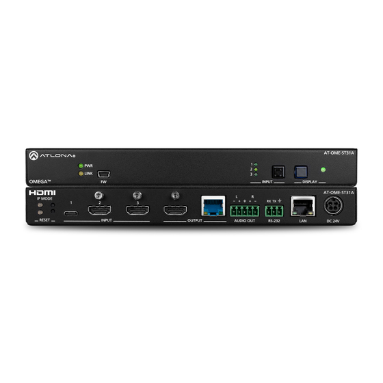
Panel Description AT-OME-ST31A LINK AT-OME-ST31A OMEGA INPUT DISPLAY Front LINK OMEGA INPUT DISPLAY AT-OME-ST31A IP MODE AT-OME-ST31A RESET INPUT OUTPUT AUDIO OUT RS-232 DC 24V IP MODE RESET INPUT OUTPUT AUDIO OUT RS-232 DC 24V Rear PWR Indicator INPUT ports This LED indicator glows solid green when the unit is Connect a USB-C cable from a video source to powered. -
Page 10: Installation
USB-C device as well as a PoE over HDBaseT receiver. The power supply (part no. AT-PS-245-D4) can be purchased from Atlona. Refer to the tables below for recommended cabling when using Altona products with HDBaseT technology. -
Page 11: Notes On Scaling
Installation Notes on Scaling The following section provides important information about how the AT-OME-ST31A processes 4K (UHD) video signals. 1. The HDMI OUTPUT port supports up to 4K @ 60 Hz, 12-bit, with HDR. 2. If the source is 4K, and the HDMI OUTPUT port is connected to a 1080p (not 4K-capable) display, then the output will be down-scaled as follows: Input Output... -
Page 12: Connection Diagram
Installation Connection Diagram Laptop Laptop 31 A E- ST -O M TE ST IN PU AT-OME-ST31A Display se T -2 32 AT-UHD-EX-100CE-RX-PSE Display AT-OME-ST31A... -
Page 13: Ip Configuration
2. Log in, using the required credentials. The factory-default username and password are listed below. Username: admin Password: Atlona 3. Click System in the menu bar. 4. Click the IP Mode toggle and set it to the STATIC IP position. -
Page 14: Auto Ip Mode
Installation Auto IP Mode If the AT-OME-ST31A is unable to detect a DHCP server within 15 seconds, then the unit will use a self-assigned IP address within the range of 169.254.xxx.xxx. If this occurs, connect the AT-OME-ST31A to a computer running Microsoft Windows®... -
Page 15: Device Operation
Device Operation LED Indicators The LED indicators on both the front and rear of the unit provide basic information on the current status of the AT- OME-ST31A. Description Solid green • Unit is receiving power using the optional 24 V DC power supply (not included) or the Ethernet cable connected between the HDBaseT OUTPUT port and a PoE over HDBaseT-compatible receiver. -
Page 16: Input Switching
Device Operation Input Switching Switching between any of the three input ports can be performed either manually or automatically. The following section covers both methods. Manual Switching 1. Press and release the INPUT button on the front panel to cycle between INPUT 1 (USB-C), INPUT 2 (HDMI), and INPUT 3 (HDMI) inputs. -
Page 17: Hdcp Content
Username: admin Password: Atlona 3. Click A/V Settings in the menu bar and locate the HDCP section. 4. Click the USBC toggle switch and set it to the OFF position. This will instruct the source device to send non- HDCP content, if possible. -
Page 18: Controlling Audio
2. Log in as the admin user with the required credentials. The factory-default username and password for the admin user are listed below: Username: admin Password: Atlona 3. Click A/V Settings in the menu bar. 4. Locate the Audio section. - Page 19 Device Operation 4. Locate the Audio section. Any of the three inputs can be set to receive either the existing digital audio from the source, or an external analog source. 5. Set the Analog Output toggle switch to the ON position. Audio from the source will be de-embedded and output on the AUDIO OUT port.
-
Page 20: Password Management
2. Log in as the admin user with the required credentials. The factory-default username and password for the admin user are listed below: Username: admin Password: Atlona 3. Click the Config tab. 4. Enter the current password in the Old Password field. -
Page 21: Resetting To Factory Defaults
The default username and password are listed below: Username: admin Password: Atlona 2. Click System in the menu bar and locate the System section. 3. Click the Factory Default button. 4. Once the Login screen appears, the reset procedure will be complete. -
Page 22: Configuration And Management Interfaces
Introduction to the Web Server The AT-OME-ST31A includes a built-in web server. Atlona recommends that the web server be used to set up the AT-OME-ST31A, as it provides intuitive management of all features. Follow the instructions below to access the webGUI. -
Page 23: Menu Bar
Configuration and Management Interfaces 7. The Info page will be displayed. Menu Bar The dark-colored bar, near the top of the screen, is the menu bar. When the mouse is moved over each menu element, it will be highlighted in light orange. Once the desired menu element is highlighted, click the left mouse button to access the settings within the menu. -
Page 24: Info Page
Software Version The version of firmware that the AT-OME-ST31A is running. Always make sure to check the AT-OME-ST31A product page, on the Atlona web site, for the latest version of firmware. On-Time(d-h:m:s) Displays how long the system has been powered since the last reboot/reset. -
Page 25: A/V Settings Page
Configuration and Management Interfaces A/V Settings Page The A/V Settings page is divided into three sections: Video, Audio, and HDCP. The Video section allows the preferred input timing to be selected as well as whether or not HDCP content is allowed to pass. The Audio section provides options to control the output audio volume, muting, treble, and bass. - Page 26 Configuration and Management Interfaces Scaler Pass-Through Click this toggle switch to enable or disable the scaler pass-through feature. When set to the ON position, no scaler processing is used and the output resolution / timing will be the same as the input source. When disabled (OFF), 4K content will be down-scaled to 1080p.
-
Page 27: Display Page
CEC command structure defined in HDMI 1.2a. It is recommended that dealers re- quest an evaluation product from Atlona, before designing a system using the CEC protocol. If this is not possible, then other control methods will need to be considered, in order to control displays using Atlona products. - Page 28 Configuration and Management Interfaces Control Type Sets the control method for sending commands. The following options are available: RS-232, IP, CEC. Setting Description RS-232 RS-232 is used to send commands. Commands are sent over IP. Uses CEC to send commands. RS-232 / IP Commands Provides customization of RS-232 / IP control device commands.
-
Page 29: Rs-232
Configuration and Management Interfaces RS-232 Page RS-232 Parameter Setting This section allows the RS-232 settings to be specified for HDBaseT and Console. • RS232 over HDBaseT If the AT-OME-ST31A is connected to a device such as the AT-UHD-EX-100CE-RX-PSE, the drop-down list boxes will be disabled and the HDBaseT baud rate will be locked at 115200. -
Page 30: Edid Page
Configuration and Management Interfaces EDID Page EDID Settings Click these drop-down lists to select the desired EDID to be used for each input. The following EDID presets are available. When selecting an EDID, make sure that the display/sink device is capable of supporting the resolution/ timing. -
Page 31: Time Page
Configuration and Management Interfaces Time Page SNTP Configuration Simple Network Time Protocol (SNTP) is a simplified version of the Network Time Protocol (NTP), and can be used to set the time for the unit. SNTP is used to receive time services from other servers. However, it cannot be used to provide time servers to other systems. -
Page 32: Config Page
This field cannot be changed. “admin” is the administrator user. Old Password Enter the current password for the “admin” username in this field. The default password is “Atlona”. New Password Enter the new password fro the “admin” username in this field. -
Page 33: System Page
Configuration and Management Interfaces System Page The System page is divided into two sections: Network and System. The Network section allows configuration of the IP settings of the AT-OME-ST31A. The System section provides controls for resetting the AT-OME-ST31A to factory-default settings and updating the firmware. MAC Address This field displays the MAC address of the AT-OME-ST31A. - Page 34 Configuration and Management Interfaces Telnet Timeout Click this drop-down list to select the timeout interval, in seconds. Range is: 1 to 10000 seconds, or Never. Hostname Displays the hostname of the AT-OME-ST31A, as it would appear on a network. To change the hostname, type the new hostname in this field and click the Save button.
-
Page 35: Solution Setup And Configuration Guide
3. Enter the login credentials and click the Submit button. The default credentials are listed below: Username: admin Password: Atlona 4. Click the Submit button or press the [ENTER] key. 5. Click A/V Settings in the menu bar. The A/V Settings page will be displayed. AT-OME-ST31A... - Page 36 Solution Setup and Configuration Guide 6. Click the Auto Switch toggle button to enable (ON) or disable (OFF) auto-switching. 7. Click the Fallback Input drop-down list to select the desired mode of operation. Fallback Input Description USBC Automatically switches to USB-C. HDMI1 Automatically switches to HDMI 1.
-
Page 37: Display Control
4. The Login page will be displayed. Enter the required credentials. The default credentials are shown below: Username: admin Password: Atlona 5. Click the Submit button or press the [ENTER] key on the keyboard. 6. Click RS-232 in the menu bar. The RS-232 page will be shown. AT-OME-ST31A... - Page 38 Solution Setup and Configuration Guide 7. Set the RS-232 settings for the display (sink) device, under the RS232 Console section. These settings must match the device settings for the display. Otherwise, RS-232 control will not function. Refer to the User Manual of the display device for information.
- Page 39 Solution Setup and Configuration Guide 13. Continue fine-tuning the device selection by clicking the Products and Model drop-down lists. Once all fields have been set to the proper values, the AT-OME-ST31A will populate the command fields with the proper values, based on the selected device.
-
Page 40: Using Ip
4. The Login page will be displayed. Enter the required credentials. The default credentials are shown below: Username: admin Password: Atlona 5. Click the Submit button or press the [ENTER] key on the keyboard. 6. Click Display in the menu bar. The Display page will be shown. AT-OME-ST31A... - Page 41 Solution Setup and Configuration Guide 7. Under System Settings, click the Control Type drop-down list and select IP. 8. Locate the TCP/IP Settings of Controlled Device section and enter the following information: a. IP Mode If the device does not require a login, then set this drop-down value to Non-Login. If the device requires login credentials, select Login from the drop-down list.
- Page 42 Solution Setup and Configuration Guide 11. Continue fine-tuning the device selection by clicking the Products and Model drop-down lists. Once all fields have been set to the proper values, the AT-OME-ST31A will populate the command fields with the proper values, based on the selected device.
-
Page 43: Pass-Through Mode
Solution Setup and Configuration Guide Pass-through mode In pass-through mode, RS-232 commands are sent to the AT-OME-ST31A and then transmitted over HDBaseT to the receiver unit, and then to the display (sink) device. 1. Connect the RS-232 cable between the control system and the AT-OME-ST31A. 2. - Page 44 The factory-default username and password are listed below: Username: admin Password: Atlona 2. Click RS-232 in the menu bar. 3. Select the proper baud rate, data bit, parity, and stop bit settings for the HDBaseT OUTPUT port.
-
Page 45: Control Mode
Solution Setup and Configuration Guide Control Mode In control mode, RS-232 commands are sent from a computer or control system (DTE) to the AT-OME-ST31A (DCE). This method allows direct control of the matrix for routing, IP configuration, powering-on / powering-off and other functions. -
Page 46: Appendix
Appendix Updating the Firmware Updating the firmware can be completed using either the USB interface or the web server. Atlona recommends using the web server for updating the firmware. However, if a network connection is not available, the AT-OME- ST31A firmware can be updated using a USB-A to USB mini-B cable. -
Page 47: Using Usb
Appendix 7. Click the OK button to begin the firmware update process. Click the Cancel button to cancel the process. 8. After the firmware update process is complete, the Login screen will be displayed. Using USB Requirements: • AT-OME-ST31A • Firmware file •... - Page 48 Appendix 3. The USB UPDATE folder will be displayed. If this folder is not displayed, automatically, select the USB UPDATE drive from Windows Explorer. 4. Delete all files from the USB UPDATE drive, if any are present. 5. Drag-and-drop the firmware file to the drive. 6.
-
Page 49: Mounting Instructions
Appendix Mounting Instructions The AT-OME-ST31A includes two mounting brackets, which can be used to attach the unit to any flat surface. Use the two enclosure screws, on the sides of the unit to attach the mounting brackets. 1. Using a small Phillips screwdriver, remove the two screws from the left side of the enclosure. T 3 1 E - S - O M... - Page 50 Appendix 4. Repeat steps 1 and 2 to attach the second mounting bracket to the opposite side of the unit. 5. Mount the unit to a flat surface using the oval-shaped holes, on each mounting bracket. If using a drywall surface, a #6 drywall screw is recommended.
-
Page 51: Specifications
Appendix Specifications Video HDMI Specification HDMI 2.0 HDCP 1.4, 2.2 (1), UHD/HD/SD 4096x2160 (DCI) @ 60 /30/25/24 Hz, 3840×2160 (UHD) @ 60 /30/25/24 Hz, 1080p @ 60/59.9/50/30/29.97/25/24/23.98 Hz, 1080i @ 60/59.94/50 Hz, 720p @ 60/59.94/50 Hz, 576p @ 50 Hz, 576i @ 50 Hz, 480p @ 60/59.96 Hz, 480i @ 60 Hz VESA 2560×1600, 2048×1536, 1920×1200, 1680×1050, 1600×1200, 1440×900, 1400×1050, 1280×1024,... - Page 52 Appendix USB-C Device Charging Capability 60 W @ 20 V / 3 A, 36 W @ 12 V / 3 A, and 15 W @ 5 V / 3 A Controls and Indicators INPUT, DISPLAY 2 - momentary, tact-type IP MODE, RESET 2 - momentary, tact-type, recessed PWR indicator 1 - LED, green...
-
Page 53: Index
Index IP address default Audio displaying muting setting Mounting instructions compatibility Configuration auto IP mode Operating notes setting the IP address switching the IP mode Connection diagram Panel descriptions instructions Password Contents setting package table of Control system using Reset Customer support factory-default RS-232... - Page 54 • © 2019 Atlona Inc. All rights reserved. “Atlona” and the Atlona logo are registered trademarks of Atlona Inc. All other brand names and trademarks or registered trademarks are the property of their respective owners. Pricing, specifications and availability subject to change without notice. Actual products, product images, and online product images may vary from images shown here.
Need help?
Do you have a question about the OMEGA AT-OME-ST31A and is the answer not in the manual?
Questions and answers