Advertisement
Quick Links
CSA10-41-DIN
COMPONENTS
Before assembling your antenna please ensure that all the components below are included in the kit.
M-8569
CENTRE SCREEN
QTY: 1
SMALL CLAMP PLATE
QTY:1
M8 FLAT WASHER
M8x80 (3" LONG)
HEX HEAD BOLT
M8 FLAT WASHER
M8 SPRING WASHER
M8 HEX NUT
M8x80 BOLT ASSEMBLY
QTY: 16
INS-40094-1
All manuals and user guides at all-guides.com
M-8569
SIDE SCREENS
QTY: 2
LARGE CLAMP PLATE
QTY: 2
M8 FLAT WASHER
M8x130 (5" LONG)
HEX HEAD BOLT
M8 FLAT WASHER
M8 SPRING WASHER
M8 HEX NUT
M8x130 BOLT ASSEMBLY
QTY: 2
www.bird-technologies.com
148-174 MHz
M-8648
DIPOLE ASSEMBLY
QTY: 1
CORNER BRACKET
QTY: 8
M16 HEX NUT
M16 SPRING WASHER
M16 FLAT WASHER
M16x250 (10" LONG)
THREADED ROD
M16 STUD ASSEMBLY
QTY: 4
PAGE 1 OF 4
©RF Industries Pty Ltd 2009
Advertisement

Related Manuals for RFI CSA10-41-DIN


Summary of Contents for RFI CSA10-41-DIN
- Page 1 All manuals and user guides at all-guides.com 148-174 MHz CSA10-41-DIN ASSEMBLY INSTRUCTIONS COMPONENTS Before assembling your antenna please ensure that all the components below are included in the kit. M-8569 M-8569 M-8648 SIDE SCREENS CENTRE SCREEN DIPOLE ASSEMBLY QTY: 2...
-
Page 2: Antenna Assembly
All manuals and user guides at all-guides.com 148-174 MHz CSA10-41-DIN ANTENNA ASSEMBLY STEP 1: ASSEMBLE SIDE SCREENS TO CENTRE SCREEN AS PICTURED BELOW USING THE M8 BOLT ASSEMBLY AND CORNER BRACKETS INCLUDED IN THE KIT. TIGHTEN M8 BOLTS TO 25NM (19 lbf.ft) -
Page 3: Assembly Instructions
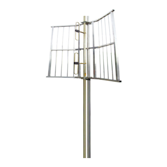
All manuals and user guides at all-guides.com 148-174 MHz CSA10-41-DIN ASSEMBLY INSTRUCTIONS continued STEP 3: FIT THE 4 M16 THREADED ROD ASSEMBLIES TO THE CENTRE SCREEN AS DEPICTED BELOW. LEAVE APPROXIMATELY 150mm (6") PROTRUDING OUT THE BACK SIDE. TIGHTEN TO 70Nm (50lbf.ft) CENTRE SCREEN Approx. - Page 4 All manuals and user guides at all-guides.com 148-174 MHz CSA10-41-DIN ASSEMBLY INSTRUCTIONS continued TYPICAL INSTALLATION SCREENED ARRAY ASSEMBLY CSA-10-41-DIN OUTRIGGER TOWER CLAMPS TOWER MOUNT POLE STRAIN RELIEVE FEED CABLE BACK TO SUPPORT STRUCTURE. SEAL CONNECTOR WITH A SUITABLE SELF AMALGAMATING TAPE.
Need help?
Do you have a question about the CSA10-41-DIN and is the answer not in the manual?
Questions and answers