
Related Manuals for Leggett & Platt S-Cape 2.0


Summary of Contents for Leggett & Platt S-Cape 2.0
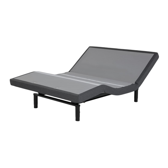
- Page 1 owners manual S-cape 2.0 / S-cape + 2.0 / ® ® G-122 NWH Simplicity ™ G-122 G-122 USB Simplicity ™ S-cape 2.0 / S-cape + 2.0 ® ® LPAdjustableBases.com...
-
Page 3: Table Of Contents
CONTENTS Advisory ........................4 Acoustics ........................6 Installation ......................... 7 Remote Control Function .................... 11 Remote Control Programming ..................12 Power Down Operation ....................15 Troubleshooting ......................18 Accessories ....................... 19 Warranty ........................20 If adjustable base does not operate or if parts are missing, call: (800) 888-3078... -
Page 4: Advisory
ADVISORY IMPORTANT INFORMATION READ THE FOLLOWING INFORMATION CAREFULLY BEFORE USING THIS PRODUCT READ ALL INSTRUCTIONS BEFORE USING PRODUCT RATINGS The base lift motors are not designed for continuous use. Reliable operation and full life expectancy will be realized as long as the lift motors do not operate any more than five (5) minutes over a thirty (30) minute period, or approximately 15% duty cycle. - Page 5 ADVISORY IMPORTANT INFORMATION READ THE FOLLOWING INFORMATION CAREFULLY BEFORE USING THIS PRODUCT SMALL CHILDREN / PETS WARNING FCC COMPLIANCE After the base is unboxed, immediately dispose of The equipment has been tested and found to packaging material as it can smother small children comply with the limits for a Class B digital device, and pets.
-
Page 6: Acoustics
ACOUSTICS LIFTING/LOWERING MECHANISMS LOCATION ENVIRONMENT The lift/lower feature will emit a minimal humming The level of sound experienced during operation sound during operation. This is normal. is directly related to the location environment. For example, when a base is located on a hardwood floor During operation, the lift arm wheels make contact with the massage feature in operation, a vibrating with the platform support of the base. -
Page 7: Installation
INSTALLATION For installation and setup, complete the numbered procedure indicated below and on the following pages: STEP 1 Before discarding any packing materials, check the base shipping carton and verify the following items are included: WARRANTY ACTIVATION CARD (S-cape + 2.0 only) ®... - Page 8 INSTALLATION STEP 2 READ ALL INSTRUCTIONS BEFORE USING Uncoil the main power cord and extend it out head end of base, then remove the hardware box from WARNING WARNING shipping container. Cut the zip-tie and remove the mattress retainer. POWER CORDS MUST NOT INTERFERE WITH ANY ADJUSTABLE BASE STEP 3 MECHANISMS.
- Page 9 INSTALLATION STEP 5 Remove the shipping carton and plastic packaging from the adjustable base frame. Remove protective film from Micro-Hook™ strips, if applicable. Note: S-cape + 2.0 ® base includes a 4-port charging hub at head end of base (FIGURE 2). FIGURE 2 4-PORT CHARGING HUB (S-cape...
- Page 10 INSTALLATION MATTRESS RETAINER INSTALLATION (OPTIONAL) Mattress is equipped with a Micro-Hook™ system IMPORTANT! to captivate the mattress (FIGURE 4), but if THIS PRODUCT SHOULD NOT BE USED WITH desired a mattress retainer can also be used. If EITHER A DUST RUFFLE OR A MATTRESS installing a mattress retainer, proceed to Step 9.
-
Page 11: Remote Control Function
REMOTE CONTROL FUNCTION LOCK BUTTON FLAT BUTTON Pressand hold to lower the base to the To lock / unlock the remote control flat position. This button will also turn buttons, press and hold lock button for 3 seconds. Backlight will flash 3 times. off the massage motors. -
Page 12: Remote Control Programming
REMOTE CONTROL PROGRAMMING Program One Remote to Operate One Base - Bases Program One Remote to Operate Two Bases - Bases are factory programmed to operate as one remote are factory programmed to operate individual control to one base. If reprogramming is required, bases. - Page 13 REMOTE CONTROL PROGRAMMING Program Two Remotes to Operate One Base - Bases Program Two Remotes to Operate Two Bases - are factory programmed to operate individual Bases are factory programmed to operate individual bases. To program two remotes to operate one bases.
- Page 14 REMOTE CONTROL PROGRAMMING Reprogram Two Remote Controls for Individual Base Operation - Bases are factory programmed to operate individual bases. To reprogram bases synced to multiple remote controls, perform the following numbered procedure. Individual base BASE 1 operation will result. If programming fails, initiate REMOTE CONTROL 1 the programming procedure a second time.
-
Page 15: Power Down Operation
POWER DOWN OPERATION To lower base to the flat position during an electrical power outage, complete the following procedure: NOTE FOR EMERGENCY USE ONLY. BATTERIES ARE NOT TO BE USED FOR NORMAL OPERATION OF BASE (9-VOLT ALKALINE BATTERIES NOT INCLUDED) STEP 1 Verify power supply is unplugged from electrical power source. - Page 16 POWER DOWN OPERATION STEP 4 Push tab in on control box connection cord and pull out to remove control box connection cord from power supply “brick” (FIGURE 8). FIGURE 8 POWER SUPPLY “BRICK” CONTROL BOX CONNECTION CORD STEP 5 Connect control box connection cord to power down device (FIGURES 9 and 10).
- Page 17 POWER DOWN OPERATION FIGURE 10 CONTROL BOX CONNECTION CORD CONNECTED TO POWER DOWN DEVICE STEP 6 Press the FLAT BUTTON on the remote control until the base is in the flat position. BASE WILL MOVE TO THE FLAT POSITION VERY SLOWLY.
-
Page 18: Troubleshooting
TROUBLESHOOTING If the adjustable base fails to operate, investigate the symptoms and possible solutions provided in the chart below: SOLUTION SYMPTOM electrical outlet. A grounded, electrical surge protection device is recommended. Test outlet by plugging in another working appliance. Remote control illuminates and appears to be operable, but will not activate base. -
Page 19: Accessories
ACCESSORIES OPTIONAL EQUIPMENT Contact customer service toll free (800-888-3078) to order the accessories indicated in the chart below. ACCESSORY DESCRIPTION CODE IMAGE 4B2385 (set of 4, replaces legs) 3” Legs 4B2284 (set of 4) 4” Legs 4B1833 (set of 4) 5”... -
Page 20: Warranty
1 YEAR, 3 YEAR AND 25 YEAR LIMITED WARRANTY In this warranty: “Adjustable base” means the adjustable bed foundation sold by L&P to the dealer. The “adjustable base” does not include the mattress. “L&P” means Leggett & Platt, Incorporated. “Purchaser” and “You” both mean the consumer who is the original purchaser of this adjustable base made by L&P. - Page 21 1 YEAR, 3 YEAR AND 25 YEAR LIMITED WARRANTY Repair or replacement shall be the sole remedy of the L&P makes no other warranty whatever, express or Purchaser. There shall be no liability on the part of L&P implied, and all implied warranties of merchantability and for any special, indirect, incidental, or consequential fitness for a particular purpose are disclaimed by L&P and damages or for any other damage, claim, or loss not...
- Page 24 290-0010-b EDR13XXX 1/17 NATIONWIDE CUSTOMER SERVICE (800) 888-3078 toll free: © 2017 Leggett & Platt Adjustable Bed Group, a division of Leggett & Platt Incorporated...
Need help?
Do you have a question about the S-Cape 2.0 and is the answer not in the manual?
Questions and answers