Table of Contents
Advertisement
Advertisement
Table of Contents

Related Manuals for YASKAWA MotionSuite MP940


Summary of Contents for YASKAWA MotionSuite MP940
- Page 1 Artisan Technology Group is your source for quality new and certified-used/pre-owned equipment SERVICE CENTER REPAIRS WE BUY USED EQUIPMENT • FAST SHIPPING AND DELIVERY Experienced engineers and technicians on staff Sell your excess, underutilized, and idle used equipment at our full-service, in-house repair center We also offer credit for buy-backs and trade-ins •...
- Page 2 MotionSuite MP940 Machine Controller Hardware Manual Artisan Technology Group - Quality Instrumentation ... Guaranteed | (888) 88-SOURCE | www.artisantg.com...
-
Page 3: Table Of Contents
Table of Contents Section 1: Introduction..................1 Machine Controller ..................1 Part Numbers ....................3 Section 2: Startup....................5 Mounting Orientation ..................5 Mounting the MP940 to an SGDH ..............6 Mounting the Battery Holder ...............8 Power / Connections ..................11 Wiring - Single Phase ................12 Wiring - Three Phase ................13 SGDH and MP940 Startup Procedure ............14 Section 3: DIP Switch Definition ..............15 Section 4: LED Indicators................19... - Page 4 Section 6: Digital I/O ..................39 Digital I/O Specifications ................40 Section 7: Limit Switch Inputs ...............43 Section 8: Analog I/O ..................45 Analog Input ....................45 Analog Output....................46 Section 9: External Encoder ................47 External Encoder Specifications ..............48 Section 10: Registration Latch................49 Main Encoder Registration Input...............50 External Encoder Registration Input............51 Section 11: Maintenance.................53 Battery Life ....................53...
-
Page 5: Section 1: Introduction
MotionSuite™ MP940 Machine Controller Hardware Manual Section 1: Introduction Section 1: Introduction The MP940 is a 1.5 axis machine controller which connects to an SGDH servo amplifier via dual-port RAM. This combination makes a fully integrated one-and-a-half-axis machine controller. It can be used to perform point-to-point positioning, or following of external devices. - Page 6 MotionSuite™ MP940 Machine Controller Hardware Manual Section 1: Introduction SGDH MP940 Local MP940 Motion Profiler Counter External SERIAL Network Encoder RS-232C Motion Works+ Network Network RS-422/485 Device 1 Device 2 Programming Device Figure 1.2: Block Diagram of MP940 Functions a) MP940 Personal Computer SGDH Amplifier MP940...
-
Page 7: Part Numbers
MotionSuite™ MP940 Machine Controller Hardware Manual Section 1: Introduction Part Numbers Description Item Number Machine Controller with Mechatrolink Interface JEPMC-MC400 Machine Controller with DeviceNet Interface JEPMC-MC410 1.0m 50 Pin I/O Cable JZSP-CKI01-1 2.0m 50 Pin I/O Cable JZSP-CKI01-2 3.0m 50 Pin I/O Cable JZSP-CKI01-3 1.0m 50 Pin I/O Cable (with terminal block) JUSP-TA50P... - Page 8 MotionSuite™ MP940 Machine Controller Hardware Manual Section 1: Introduction NOTES: Artisan Technology Group - Quality Instrumentation ... Guaranteed | (888) 88-SOURCE | www.artisantg.com...
-
Page 9: Section 2: Startup
MotionSuite™ MP940 Machine Controller Hardware Manual Section 2: Startup Section 2: Startup Mounting Orientation Mount the SGDH and MP940 in the appropriate direction for proper cooling, as shown on the left below. Correct Incorrect SGDH MP940 Figure 2.1: Mounting Orientation Artisan Technology Group - Quality Instrumentation ... -
Page 10: Mounting The Mp940 To An Sgdh
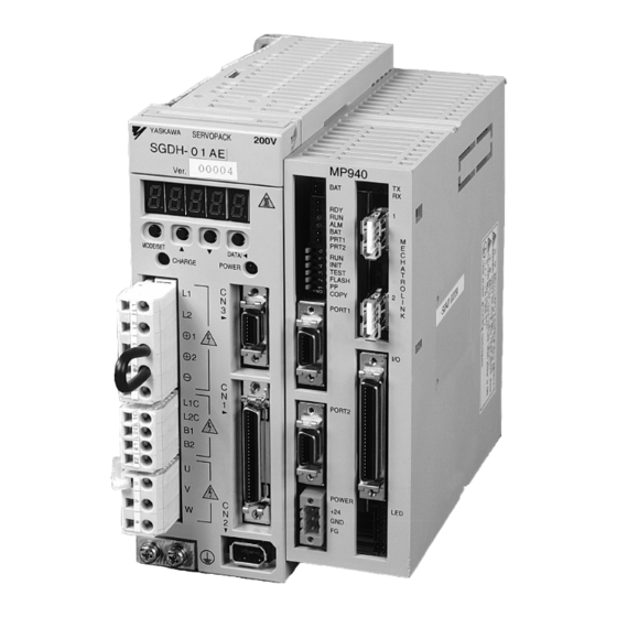
1. Insert the lower two mounting notches into the mounting holes at the bottom of the right side of the SGDH. Connector (connected to servo amplifier) Servo Amplifier Connector YASKAWA SERVOPACK SGDH- Figure 2.2: Mounting the MP940 to an SGDH Servo Amplifier 2. - Page 11 MotionSuite™ MP940 Machine Controller Hardware Manual Section 2: Startup There are two types of mounting clips due to different sizes of servo amplifiers. See the following table before mounting. Clip A × 2 Clip B × 1 SGDH-A3 SGDH-05 SGDH-20 SGDH-60 SGDH-A5 SGDH-08...
-
Page 12: Mounting The Battery Holder
MotionSuite™ MP940 Machine Controller Hardware Manual Section 2: Startup 3. Insert the mounting clips into the mounting holes in the MP940, as shown in the figure below. Mounting Hole Servo Amplifier Clip Clip Mounting MP940 Hook Figure 2.3: Inserting the Mounting Clips 4. - Page 13 MotionSuite™ MP940 Machine Controller Hardware Manual Section 2: Startup MP940 Upper lock ① PRT1 PRT2 INIT TEST Battery Holder FLASH Mounting Holes COPY → PORT1 ② Push in this lock PORT2 POWER +24V Figure 2.4: Mounting the Battery Holder 3. Push the holder up to ensure it is securely mounted. MP940 PRT1 PRT2...
- Page 14 MotionSuite™ MP940 Machine Controller Hardware Manual Section 2: Startup Battery A battery is needed during absolute encoder use for both MP940 and SGDH position data memory. Battery for absolute encoder position data memory Battery for RAM data backup and position data memory SGDH Servo MP940...
-
Page 15: Power / Connections
MotionSuite™ MP940 Machine Controller Hardware Manual Section 2: Startup Power / Connections The MP940 must be supplied with 24VDC. Detailed information on power requirements for the SGDH are found in the SGDH User’s Manual. Power Consumption Recommended Fuse Size Type of Power Supply Regulated 24VDC ±10% MP940 PRT1... -
Page 16: Wiring - Single Phase
MotionSuite™ MP940 Machine Controller Hardware Manual Section 2: Startup Wiring - Single Phase Apply power to the SGDH and MP940 at the same time. If the SGDH is not powered within 10 seconds after turning power ON to the MP940 (or vice versa), the units will not communicate with each other. -
Page 17: Wiring - Three Phase
MotionSuite™ MP940 Machine Controller Hardware Manual Section 2: Startup Wiring - Three Phase Apply power to the SGDH and MP940 simultaneously. If the SGDH is not powered within 10 seconds after turning power ON to the MP940 (or vice versa), the units will not communicate with each other. -
Page 18: Sgdh And Mp940 Startup Procedure
MotionSuite™ MP940 Machine Controller Hardware Manual Section 2: Startup SGDH and MP940 Startup Procedure Follow the steps below to set up the system. 1. Set the DIP switch of the MP940 as “MEMORY CLEAR”. (Only ‘INIT’ and TEST are ON.) 2. -
Page 19: Section 3: Dip Switch Definition
MotionSuite™ MP940 Machine Controller Hardware Manual Section 3: DIP Switch Definition Section 3: DIP Switch Definition The function of the six switches is explained in the table below. INITIAL TEST FLASH COPY Figure 3.1: MP940 DIP Switches DIP Switch Settings Default Number Name... - Page 20 MotionSuite™ MP940 Machine Controller Hardware Manual Section 3: DIP Switch Definition Memory Initialization To erase the application program, variables, and configuration data, set the DIP switches in the following order. Step 1 Step 2 Step 3 Step 4 Step 5 Turn the MP940 Turn the INIT and Turn on the power,...
- Page 21 MotionSuite™ MP940 Machine Controller Hardware Manual Section 3: DIP Switch Definition Flash Memory Operation Outline Of Flash Operation Programs created by the user are normally stored in RAM. The CPU executes programs stored in RAM. The programs stored in RAM can also be saved to the flash memory.
- Page 22 MotionSuite™ MP940 Machine Controller Hardware Manual Section 3: DIP Switch Definition Copying Servo Amplifier Pn Data from MP940 to SGDH It is possible to load parameter data that was downloaded to the controller via MotionWorks or MotionWorks+ by turning off all DIP switches except the copy switch.
-
Page 23: Section 4: Led Indicators
MotionSuite™ MP940 Machine Controller Hardware Manual Section 4: LED Indicators Section 4: LED Indicators LED Display The MP940 runs a series of tests during start-up. If an error is detected, the ERR LED flashes, and the content of the error corresponds to the number of flashes. MotionSuite™... - Page 24 MotionSuite™ MP940 Machine Controller Hardware Manual Section 4: LED Indicators I/O Status LED The status of the digital inputs and outputs can be displayed by using an LED block accessory. Signal Name Note Signal Name Note — Power (+5V) — —...
-
Page 25: Section 5: Communications
MotionSuite™ MP940 Machine Controller Hardware Manual Section 5: Communications Section 5: Communications Serial Communication The MP940 is equipped with one (1) RS-232C port and one (1) RS-422/485 port. PORT1 (RS-232) is the programming port. The MP940 operates as either a master or slave according to setting in the MotionSuite™... -
Page 26: System Configuration
MotionSuite™ MP940 Machine Controller Hardware Manual Section 5: Communications System Configuration The figure below illustrates connection of a PC and an operator interface to the MP940. MP940 PRT1 PRT2 INIT TEST FLASH COPY ¨ PORT1 RS-232C RS-422 PORT2 POWER +24V Display Panel Figure 5.2: Serial System Configuration... -
Page 27: Communication Specifications
MotionSuite™ MP940 Machine Controller Hardware Manual Section 5: Communications Communication Specifications Item Specification Interface RS-232, 1 Port RS-422/485 1 Port Connector RS-232 PORT1 MDR-14pin/female RS-422/485 PORT2 MDR-14pin/female Transmission RS-232: 15m Maximum Range RS-422/485: 300m Maximum Baud Rate RS-232 PORT1 9600, 14400, 19200bps RS-422/485 PORT2: 9600, 14400, 19200bps Synchronization... - Page 28 MotionSuite™ MP940 Machine Controller Hardware Manual Section 5: Communications Connector pins and signal names of port 2 Signal Signal Description Description Name Name + side of transmission + side of transmission data data PORT2 - side of transmission data - side of transmission data + side of received data + side of received data - side of received data...
- Page 29 MotionSuite™ MP940 Machine Controller Hardware Manual Section 5: Communications RS422/485 Interface Cable 1. Make sure that the drive system, control system, power system, and other transmission systems are separate from each other (i.e., do not run the power wire with the control wire). 2.
- Page 30 MotionSuite™ MP940 Machine Controller Hardware Manual Section 5: Communications Counterpart MP940 PORT2 MP940 PORT2 Node SHIELD If connecting multiple The following will result MP940s together, wire if the MP940 them as shown here. counterpart is the same. MP940 PORT2 MP940 PORT2 MP940 PORT2 MP940 PORT2 SHIELD...
-
Page 31: Mechatrolink
Section 5: Communications Mechatrolink The Mechatrolink network option is included with MP940 part number JEPMC-MC400. Mechatrolink is a high-speed Yaskawa field network. This network allows for a master / slave configuration. The MP940 can be used as a master or a slave. -
Page 32: Mechatrolink Connection
MotionSuite™ MP940 Machine Controller Hardware Manual Section 5: Communications Mechatrolink Connection The following figure shows the connection of the MP940 module to an I/O350 unit. Use the standard cable (JEPMC-W6000-A3) when connecting an MP940 module to an I/O350, or when connecting one I/O350 to another I/O350. MP940 PRT1 PRT2... -
Page 33: Devicenet
MotionSuite™ MP940 Machine Controller Hardware Manual Section 5: Communications The MP940 is used as a slave node: Upper-Level Master Controller Node 14 nodes MP940 MP940 MP940 SGDH SGDH SGDH maximum Slave Nodes Node 4 ST#1 The MP940 cannot communicate directly to the I/O350 or distributed I/O if configured as a slave. -
Page 34: Setting The Network Address
MotionSuite™ MP940 Machine Controller Hardware Manual Section 5: Communications Setting the Network Address There are two rotary switches on the side of the MP940D. Rotate the switches to the appropriate node address. Every device on the network must have a unique address. For example, to set the unit to address 46, set the left dial to “4”... -
Page 35: Devicenet Status Leds
MotionSuite™ MP940 Machine Controller Hardware Manual Section 5: Communications DeviceNet Status LEDs There are two status LEDs above the network connector. Their display is either green or red, depending on the current status. The left LED is MS (Module Status), and the right LED is NS (Network Status). -
Page 36: Troubleshooting
MotionSuite™ MP940 Machine Controller Hardware Manual Section 5: Communications Troubleshooting When the LED detects an error during DeviceNet communications, it reports the error via the indicators. The following table gives probable causes and possible solutions. Master Troubleshooting the Master Indicators Problem Probable Cause Possible Solution... - Page 37 MotionSuite™ MP940 Machine Controller Hardware Manual Section 5: Communications Troubleshooting the Master Indicators Problem Probable Cause Possible Solution MS green lit No DeviceNet DeviceNet (1) Check the wiring and connections for DeviceNet NS not lit communications network error cables and connectors. (cont.) (cont.) (2) Check the baud rate for each DeviceNet device in the...
- Page 38 MotionSuite™ MP940 Machine Controller Hardware Manual Section 5: Communications Troubleshooting the Master Indicators Problem Probable Cause Possible Solution MS green lit MSG - SND Parameter (1) Verify the MSG - SND function parameter settings are NS green lit function setting error correct.
- Page 39 MotionSuite™ MP940 Machine Controller Hardware Manual Section 5: Communications Slave Troubleshooting Slaves Indicators Problem Probable Cause Possible Solution MS not lit No DeviceNet No power Check the network power supply to the MP940D. NS lit communica- supply to tions MP940D MS red lit Hardware Replace the MP940D.
- Page 40 MotionSuite™ MP940 Machine Controller Hardware Manual Section 5: Communications Slave Troubleshooting Slaves Indicators Problem Probable Cause Possible Solution MS green lit No DeviceNet No response (1) Check the wiring and connections for DeviceNet NS green flash- communica- from cables and connectors. ing (cont.) tions (cont.) DeviceNet...
- Page 41 MotionSuite™ MP940 Machine Controller Hardware Manual Section 5: Communications Slave Troubleshooting Slaves Indicators Problem Probable Cause Possible Solution MS green lit Communica- DeviceNet Remove the cause of the idle status of the DeviceNet NS green lit tions are master is in master.
- Page 42 MotionSuite™ MP940 Machine Controller Hardware Manual Section 5: Communications NOTES: Artisan Technology Group - Quality Instrumentation ... Guaranteed | (888) 88-SOURCE | www.artisantg.com...
-
Page 43: Section 6: Digital I/O
MotionSuite™ MP940 Machine Controller Hardware Manual Section 6: Digital I/O Section 6: Digital I/O The MP940 is equipped with eight digital inputs and eight digital outputs. There are two additional general purpose inputs available from the SGDH via dual port RAM. MP940 PRT1 PRT2... -
Page 44: Digital I/O Specifications
MotionSuite™ MP940 Machine Controller Hardware Manual Section 6: Digital I/O Digital I/O Specifications Digital Input Specifications Item Specification Number of Input Points Input Format Sinking or Sourcing Isolation Optical Voltage 24VDC ±20% Current Rating (ON) 5.3mA to activate Input Impedance 4.4kΩ... - Page 45 MotionSuite™ MP940 Machine Controller Hardware Manual Section 6: Digital I/O Digital Output Specifications Item Specification Number of Output Points Output Format Sinking Output Classification Transistor Output Isolation Optical Load Voltage 24VDC ±20% Load Current 100mA / Output ON Voltage 1.0V or less Response Time OFF to ON <...
- Page 46 MotionSuite™ MP940 Machine Controller Hardware Manual Section 6: Digital I/O NOTES: Artisan Technology Group - Quality Instrumentation ... Guaranteed | (888) 88-SOURCE | www.artisantg.com...
-
Page 47: Section 7: Limit Switch Inputs
MotionSuite™ MP940 Machine Controller Hardware Manual Section 7: Limit Switch Inputs Section 7: Limit Switch Inputs The limit and home inputs are wired to the SGDH amplifier as shown in the figure below. SGDH Motor V-REF Output signal mapping is possible using Pn50E~Pn510 settings. - Page 48 MotionSuite™ MP940 Machine Controller Hardware Manual Section 7: Limit Switch Inputs If your application does not require limit switches, they can be disabled. To disable the positive overtravel limit (P-OT), set the SGDH parameter Pn50A.digit3 to “8”. To disable the negative overtravel limit (N-OT), set the SGDH parameter Pn50B.digit 0 to “8”.
-
Page 49: Section 8: Analog I/O
MotionSuite™ MP940 Machine Controller Hardware Manual Section 8: Analog I/O Section 8: Analog I/O Analog Input The MP940 analog input comes from the SGDH analog input via dual port RAM. The analog input enters the SGDH on pin 5 of the CN1 connector. Normally, this is the VREF input, but when the MP940 and SGDH are combined, the VREF becomes available for general purpose. -
Page 50: Analog Output
MotionSuite™ MP940 Machine Controller Hardware Manual Section 8: Analog I/O Analog Output Item Content D/A Output Resolution 16Bit over a +/-10V range, or 328µV/bit +15V 1k Ω MP940 I/O Connector -15V External Device 47 Ω -10~+10V +10.75V +10V -32768 +32767 +30480 -30481 -10V... -
Page 51: Section 9: External Encoder
MotionSuite™ MP940 Machine Controller Hardware Manual Section 9: External Encoder Section 9: External Encoder MP940 PRT1 PRT2 INIT TEST FLASH COPY ¨ PORT1 PORT2 POWER +24V Figure 9.1: The MP940 External Encoder Artisan Technology Group - Quality Instrumentation ... Guaranteed | (888) 88-SOURCE | www.artisantg.com... -
Page 52: External Encoder Specifications
MotionSuite™ MP940 Machine Controller Hardware Manual Section 9: External Encoder External Encoder Specifications Item Content Input Format • Quadrature • Pulse and Direction • 1 channel positive, 1 channel negative Maximum Frequency 1MHz MP940 I/O Connector MP940 Pulse Generator A-phase 390Ω... -
Page 53: Section 10: Registration Latch
MotionSuite™ MP940 Machine Controller Hardware Manual Section 10: Registration Latch Section 10: Registration Latch The registration latch is used to record (i.e., latch onto) the encoder position at the moment an external signal is input (rising edge). Number of Latch Circuits Input Type Current Source Photocoupler Isolation Main encoder latch input voltage... -
Page 54: Main Encoder Registration Input
MotionSuite™ MP940 Machine Controller Hardware Manual Section 10: Registration Latch Main Encoder Registration Input The registration latch for the SGDH is wired into the 1CN connector on the amplifier. Latch registration with this input is performed from the MP940 through dual port RAM. -
Page 55: External Encoder Registration Input
MotionSuite™ MP940 Machine Controller Hardware Manual Section 10: Registration Latch External Encoder Registration Input MP940 I/O Connector 2.2kΩ 2.2kΩ LC24V LC12V 5VDC or 12VDC or 24VDC 390Ω LC5V 680Ω LATCH Artisan Technology Group - Quality Instrumentation ... Guaranteed | (888) 88-SOURCE | www.artisantg.com... - Page 56 MotionSuite™ MP940 Machine Controller Hardware Manual Section 10: Registration Latch NOTES: Artisan Technology Group - Quality Instrumentation ... Guaranteed | (888) 88-SOURCE | www.artisantg.com...
-
Page 57: Section 11: Maintenance
2. Replacement battery Use replacement battery type BA000518. This battery is not standard, and must therefore be purchased from Yaskawa. The replacement battery appears as in the diagram below. Figure 11.1: BA000518 Battery with Cable... - Page 58 MotionSuite™ MP940 Machine Controller Hardware Manual Section 11: Maintenance Prepare Replacement Battery Prepare the replacement battery as in the drawing below. MP940 PRT1 PRT2 INIT TEST FLASH COPY → PORT1 PORT2 POWER +24V Figure 11.2: BA000518 (Battery with Cable) Battery Replacement Replace the battery as follows: 1.
-
Page 59: Section 12: Specifications
MotionSuite™ MP940 Machine Controller Hardware Manual Section 12: Specifications Section 12: Specifications Physical Specifications Physical Specifications of the MP940 Item Specification Ambient Usage Temperature 0 ~ +40°C (32° ~ 130°F) Storage Temperature -25 ~ +85°C (-10° ~ 185°F) Ambient Usage Humidity 30 ~ 95%RH (no condensation) Storage Humidity 5 ~ 95%RH (no condensation) -
Page 60: Hardware Specifications
MotionSuite™ MP940 Machine Controller Hardware Manual Section 12: Specifications Hardware Specifications Hardware Specifications of MP940 Item Specifications Memory Flash: 2MB RAM: 2MB (battery backed) Communication Ports 1 RS-232C port Baud Rate Setting: 9.6k/19.2 kbps Protocol • MEMOBUS • No Protocol 1 RS-422/485 port Baud Rate Setting: 9.6k/19.2 kbps Protocol... - Page 61 MotionSuite™ MP940 Machine Controller Hardware Manual Section 12: Specifications Hardware Specifications of MP940 (Continued) Item Specifications Latch Input Latch Input Circuit: 1MHz input maximum. Latches within 30µs. Latch Input Format: quadrature; pulse and direction / channel up and channel down Latch Counter: (external signal can be switched between 5V/12V/24V) Analog Input SGDH velocity command used as analog input to controller...
- Page 62 MotionSuite™ MP940 Machine Controller Hardware Manual Section 12: Specifications NOTES: Artisan Technology Group - Quality Instrumentation ... Guaranteed | (888) 88-SOURCE | www.artisantg.com...
-
Page 63: Section 13: Dimensional Drawings And Cable Diagrams
MotionSuite™ MP940 Machine Controller Hardware Manual Section 13: Dimensional Drawings and Cable Diagrams Section 13: Dimensional Drawings and Cable Diagrams Dimensions Figure 13.1: MP940 Dimensions Artisan Technology Group - Quality Instrumentation ... Guaranteed | (888) 88-SOURCE | www.artisantg.com... - Page 64 MotionSuite™ MP940 Machine Controller Hardware Manual Section 13: Dimensional Drawings and Cable Diagrams Figure 13.2: MP940 YS15 Cable Drawing Artisan Technology Group - Quality Instrumentation ... Guaranteed | (888) 88-SOURCE | www.artisantg.com...
- Page 65 MotionSuite™ MP940 Machine Controller Hardware Manual Section 13: Dimensional Drawings and Cable Diagrams Figure 13.3: MP940 Cable Artisan Technology Group - Quality Instrumentation ... Guaranteed | (888) 88-SOURCE | www.artisantg.com...
- Page 66 MotionSuite™ MP940 Machine Controller Hardware Manual Section 13: Dimensional Drawings and Cable Diagrams Figure 13.4: I/O Cable Drawing Artisan Technology Group - Quality Instrumentation ... Guaranteed | (888) 88-SOURCE | www.artisantg.com...
-
Page 67: Connections
MotionSuite™ MP940 Machine Controller Hardware Manual Section 13: Dimensional Drawings and Cable Diagrams Connections MP940 LED2 Battery Connector LED1 PRT1 PRT2 Battery Mechatrolink INIT TEST Switch Connector FLASH COPY ¨ PORT1 Serial Port 1 PORT2 Connector Serial Port 2 POWER +24V Power Connector... -
Page 68: Connector Specifications
MotionSuite™ MP940 Machine Controller Hardware Manual Section 13: Dimensional Drawings and Cable Diagrams Connector Specifications Connector Model # of Name Connector Name Pins Controller Side Cable Side Manufacturer Battery DF3-2P-2DS Battery Connector BA000518 HIROSE Connector Serial Port PORT1 10214-52A2JL Connector Unit RS-232C 10114-3000VE Shell... -
Page 69: I/O Connector
MotionSuite™ MP940 Machine Controller Hardware Manual Section 13: Dimensional Drawings and Cable Diagrams I/O Connector Number Signal Name Reference Number Signal Name Reference Analog Input AO_GND Analog Output Ground — — — — — — — — A_ Pulse + B_Pulse + A_ Pulse - B_Pulse -... - Page 70 MotionSuite™ MP940 Machine Controller Hardware Manual Section 13: Dimensional Drawings and Cable Diagrams I/O Circuit of I/O Connector +15V 1kΩ -15V External Device Analog -10~+10V 47Ω Output External Encoder A-phase 390Ω External Encoder B-phase Digital Ground 390Ω Digital Ground Latch Input 680Ω...
-
Page 71: Mechatrolink Cables
MotionSuite™ MP940 Machine Controller Hardware Manual Section 13: Dimensional Drawings and Cable Diagrams Mechatrolink Cables Figure 13.7: Mechatrolink Cable Mechatrolink Cable The internal cable connections between the MP940 and the I/O unit are shown below: Cable Model: JEPMC-W6000- Pin No. Name Name (NC) - Page 72 MotionSuite™ MP940 Machine Controller Hardware Manual Section 13: Dimensional Drawings and Cable Diagrams External Views of Mechatrolink Cables Model JEPMC-W6000- Model: JEPMC-W6010- USB Terminator Model: JEPMC-W6020 Artisan Technology Group - Quality Instrumentation ... Guaranteed | (888) 88-SOURCE | www.artisantg.com...
- Page 73 YASKAWA ELECTRIC AMERICA, INC. 2121 Norman Drive South, Waukegan, IL 60085, U.S.A. Phone: (847) 887-7000 Fax: (847) 887-7310 Internet: http://www.yaskawa.com MOTOMAN INC. 805 Liberty Lane, West Carrollton, OH 45449, U.S.A. Phone: (937) 847-6200 Fax: (937) 847-6277 Internet: http://www.motoman.com YASKAWA ELETRICO DO BRASIL COMERCIO LTDA.
- Page 74 Artisan Technology Group is your source for quality new and certified-used/pre-owned equipment SERVICE CENTER REPAIRS WE BUY USED EQUIPMENT • FAST SHIPPING AND DELIVERY Experienced engineers and technicians on staff Sell your excess, underutilized, and idle used equipment at our full-service, in-house repair center We also offer credit for buy-backs and trade-ins •...
Need help?
Do you have a question about the MotionSuite MP940 and is the answer not in the manual?
Questions and answers