Kessel Aqualift F Basic Instructions For Installation, Operation And Maintenance
Lifting station
Hide thumbs
Also See for Aqualift F Basic:
- Installation and operating manual (216 pages) ,
- Installation, operating and maintenance instructions (180 pages) ,
- Instructions for installation, operation and maintenance (180 pages)
Table of Contents
Advertisement
Quick Links
INSTRUCTIONS FOR INSTALLATION, OPERATION
KESSEL Lifting station Aqualift F Basic
Installation
Commissioning
for the system was carried out by your specialist company:
Name/signature
Status 2017/11
AND MAINTENANCE
Instructional briefing
Date
Product advantages
City
Stamp of specialist company
The economical way to
discharge wastewater for
the private sector
With float switch to detect
switching and alarm levels
Flexible and fast thanks
to a variety of connecting
muffs
DIN EN 12050-1
Part no. 010-974
Advertisement
Table of Contents

Related Manuals for Kessel Aqualift F Basic


Summary of Contents for Kessel Aqualift F Basic
- Page 1 INSTRUCTIONS FOR INSTALLATION, OPERATION AND MAINTENANCE KESSEL Lifting station Aqualift F Basic Product advantages The economical way to discharge wastewater for the private sector With float switch to detect switching and alarm levels Flexible and fast thanks to a variety of connecting...
-
Page 2: Table Of Contents
Table of contents Introduction Product description, general ..................... 34 General instructions on using these operating and maintenance instructions ....35 How it works........................35 Type plate ......................... 36 Scope of delivery ......................37 Displays, operating keys and their functions ..............37 Component assemblies and functional properties ............ - Page 3 4.2.2 Power supply failure alarm ....................48 Overview of LED displays / information ................49 Acknowledging the alarm ....................50 Switching off the lifting station ..................50 Manual operation ......................50 Maintenance Maintenance safety notes ....................51 Maintenance intervals ....................... 51 Preparing for maintenance work ..................
-
Page 4: Introduction
Have you got any questions? We look forward to you getting in touch. Product description, general The KESSEL lifting station Aqualift F Basic (referred to as „lifting station“ from here onwards) has been designed for pumping off wastewater with and without sewage. The system tank houses the pump and the level sensor (float switch). -
Page 5: General Instructions On Using These Operating And Maintenance Instructions
Introduction General instructions on using these operating and maintenance instructions Symbols and legends used <1> Reference in the text to a legend number in an illustration Reference to an illustration • Working step Working step in numbered sequence – List Italic case design: Reference to a section / item in the control menu Italics CAUTION: Warns of a risk to persons and material. -
Page 6: Type Plate
Connection voltage and connection frequency, current consumption range Maximum pumping flow / pumping height Protective rating (IP) + mode of operation Serial number QR code Hardware revision status Hebeanlage Aqualift F Basic Aqualift F Mono/Duo XXXXX XXXXX XXXV XXHz X,XA X,XkW XXm³/h... -
Page 7: Scope Of Delivery
Introduction Scope of delivery Control unit Operating and maintenance instructions Fastening material for the control unit Drilling template for the control unit System tank with wastewater pump and level sensor Ill. [3] Displays, operating keys and their functions Control unit LED Ready for operation LED Alarm LED system tank, switch-on level reached... -
Page 8: Component Assemblies And Functional Properties
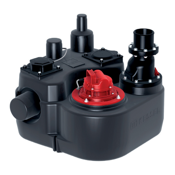
Introduction Component assemblies and functional properties Flap, backwater preventer Control unit System tank Type plate Wastewater pump Connection for pressure pipe Backwater preventer housing Ventilation device Inlet (various options, see 3.3) Level sensor (float switch)* Connection for vent pipe Manual diaphragm pump connection Servicing opening* *mutually replaced depending on the type of use (see 3.4) Ill. -
Page 9: Safety
Safety Safety Correct use The lifting station is to be used exclusively for pumping domestic wastewater with and without sewage. The system must not be used in a potentially explosive environment. • conversions or attachments • use of non-genuine spare parts •... -
Page 10: Risks Caused By The Product
Safety Risks caused by the product 2.4.1 Risk caused by special location / ambient conditions Risk caused by toxic and hazardous vapours, gases and substances (e. g. bacteria, viruses). If the lifting station is located in an inspection chamber, any necessary work must always be done by specialist staff (see 2.2). -
Page 11: Installation
We recommend using a sound-absorbent mat as acoustic insulation (to minimise the transmission of sound on the support surface). This is available as an accessory from KESSEL. Position the system tank correctly and screw to the floor at the two •... -
Page 12: Fitting The Inlet And Outlet
Installation Fitting the inlet and outlet Preparation Risk of functional problems due to suspended matter and solids deposited on the level sensor. If the inlet is to be at the muffs <26B > or <26C>, the respective muff must be sawn off at the given cutting edge. If the inlet to the system tank is to be via position <26C>, the level sensor <27>... -
Page 13: Connecting The Ventilation Pipe
Installation Connecting the ventilation pipe • Connect the venting pipe to the venting connection <28> A separate venting pipe has to be routed via the roof in accordance with DIN EN 12056-4 • Saw off the muff for the vent pipe <28> at the given cutting edge. Ill. -
Page 14: Installing The Control Unit
Installation Installing the control unit • Select the mounting position making sure that: – there is a safety socket in the direct vicinity of the control units. – The connecting cable from the wastewater pump and float switch can be installed correctly and routed to the control unit. –... - Page 15 Installation Danger through incorrectly dimensioned connection cables. The lifting station is only designed for operation with the enclosed connection cables (or equivalent). If in doubt, consult the manufacturer / supplier. • Fit end sleeves (length 8 mm) to the ends of the cables •...
-
Page 16: Connection Of A Potential-Free Contact
Installation • Connection diagram Ill. [14] 1 Mains connection 3 Float switch brown yellow blue white green/yellow pink brown grey 2 Wastewater pump green green/yellow not occupied blue brown 4 Alarm Connection for external audible alarm/ potential-free contact Connection of a potential-free contact A potential-free contact can be connected to the control unit, available from Busch-Jäger (art. -
Page 17: Initial Operation
Installation Initial operation Avoid the wastewater pump(s) running dry for a longer period (>30 seconds) at all costs, it/they could become damaged. Never switch wastewater pumps on if the system tank is not filled at least to the minimum level. 3.9.1 Initialising the control unit •... -
Page 18: Operation
Operation Operation The backwater preventer must be functional during operation, see <25> in Fig. [5], page 38 Automatic operation The lifting station is in automatic mode if no fault has been detected and the green operating LED <1> comes on The wastewater pump is switched on an off according to the wastewater level. -
Page 19: Overview Of Led Displays / Information
Operation Overview of LED displays / information Flashing PUMP Lights up / switched on Aqualift Basic Mono Switched off Flashing alternately flashing simultaneously Ill. [17] Acoustic Description Action signal (interval) Operating states Ready for operation System tank full, will be pumped out No action necessary, wastewater shortly pump can be switched off with button... -
Page 20: Acknowledging The Alarm
Operation Acknowledging the alarm If a state occurs which triggers an alarm (e.g. fault on the pump, power failure), this is indicated by the alarm LED <2> coming on and possibly one of the other LEDs (see 4.3). After the cause of the alarm has been eliminated, the alarm can be acknowledged by pressing key <6>. -
Page 21: Maintenance
- 1 year for systems in single-family homes Tip: A maintenance protocol with details of all the work carried out and the main data must be prepared for all maintenance work. You will find the maintenance protocol under Downloads at www.kessel.com. 2017/11... -
Page 22: Preparing For Maintenance Work
Maintenance Preparing for maintenance work – Make sure that the inlet to the lifting station is not used during maintenance. – Make sure that the lifting station cannot be switched on accidentally during maintenance work. This applies in particular if the control unit is in a different room to the system tank. Maintenance jobs 5.4.1 Replace battery •... - Page 23 Maintenance • Evacuate the system tank. This can done be via the connection <29> for the manual diaphragm pump (see Fig. [5] on page 38) or with a wet vacuum cleaner. • Unscrew cover of the service opening <30> Make sure that the float switch of the level sensor <27> and float switch rods are free from suspended matter •...
- Page 24 Maintenance • Remove and clean the backwater preventer <25>. To do do, unscrew screws <1> and <2> and push out the backwater preventer <25> from the side Ill. [21] fit the backwater preventer <25> again. Make sure that the • ventilation device <25A>...
-
Page 25: Troubleshooting
Troubleshooting Troubleshooting All work exceeding the activities described in Chapter may only be carried out by specialist staff (see 2.2). • Pay attention to the notes described in 5.1 and perform these if necessary Error Possible cause Remedial measure / Chapter Battery fault Battery is missing, is faulty or voltage too Check battery connection, if necessary... -
Page 26: Technical Data
Technical data Technical data Control unit Weight [kg] Operating voltage [V] 50 Hz Nominal current [A] Protective rating IP54 Protective class Plug type Earthed connector Connecting cable [m] Required fuse protection C16 A 1 pole Fuse Fault current circuit breaker recommended Microfuse 10 A M... -
Page 27: Pumping Flow
Technical data Pumping flow Pumping flow Q [m³/h] at pumping height H [m] H [m] 12.5 15 17.5 20 22.5 25 27.5 30 Q [m³/h] H [m] Q [m³/h] Ill. [23] Tightening torques for screw connections Pump at pump flange approx. -
Page 28: Dimensions, Volume
Technical data Dimensions, volume Useful volume approx. 20 litres Tank volume approx. 50 litres DN 100 DN80 DN70 DN50 Ill. [24] 58 / 180 2017/11... -
Page 29: Spare Parts
Spare Parts Pos. Description Art.Nr. Float unit Basic with gasket 680539 SPF 1300 for Aqualift Basic 680535 Impeller for SPF 1300 Aqualift F Basic 680536 Flange with gasket and screws 680537 Flange gasket 680549 Flap and flapholder 680548 Clean-Out opening incl. gasket... - Page 30 Leading in Drainage Declaration of conformity Private homes without public sewage connection 1 2 3 4 1 2 3 4 Public buildings (e.g. hospital) Public buildings (e.g. leisure facility) 1 2 3 4 Commercial buildings (e.g. hotel) Commercial buildings (e.g. industrial / manu- facturing facilities) 2 3 5 Commercial buildings...
- Page 31 INSTRUCTIONS DE POSE, D‘UTILISATION ET DE MAINTENANCE KESSEL Poste de relevage Aqualift F Basic Avantages du produit Vidange économiquement rentable pour le particulier Avec interrupteur à flotteur de détection de commutation et de niveau d‘alarme Flexible et rapide grâce à...
Need help?
Do you have a question about the Aqualift F Basic and is the answer not in the manual?
Questions and answers