
Related Manuals for Sony MKS-R4020


Summary of Contents for Sony MKS-R4020
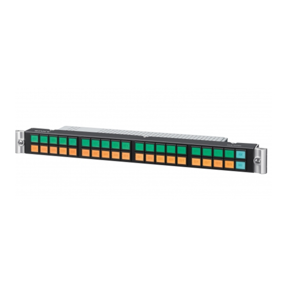
- Page 1 5-012-212-11 (1) 40 LCD Button Remote Control Panel MKS-R4020 16 Rotary Encoder Remote Control Panel MKS-E1620 Operating Instructions © 2019 Sony Corporation...
-
Page 2: Table Of Contents
Table of Contents Overview ............. 3 Features ................. 3 Connection Mode Settings ..........3 System Connection Example ......... 4 Locations and Functions of Parts......5 Front Panel ..............5 Rear Panel ..............5 Preparations............6 Notes on Installation ............. 6 Setting Up the Unit ............ -
Page 3: Overview
You can select and display different sources for each level using the breakaway function. Monitor function to watch the selection status of The MKS-R4020/MKS-E1620 is a remote control panel that other outputs (NS-BUS operation) connects to Live Element Orchestrator (LEO) and is used to... -
Page 4: System Connection Example
MKS-R3210 L3 switch L3 switch (For AV) (For AV) Dual LAN MKS-R1620 connection L2 switch L2 switch (For control) (For control) MKS-R1630 MKS-R4020 Single LAN MKS-R3210 MKS-E1620 L3 switch connection (For control) Single LAN connection MKS-R1630 MKS-R4020 MKS-R1620 Routing switcher... -
Page 5: Locations And Functions Of Parts
Locations and Functions of Parts Front Panel MKS-R4020 LCD buttons MKS-E1620 Rotary encoders LCD buttons When connected to LEO, the settings of the LCD buttons When connected to a system controller, these buttons can are made from LEO. -
Page 6: Preparations
A single system connection is the simplest connection type. Use LAN1. IP Live System Manager LAN1 MKS-R4020 Dual LAN redundancy system connection A dual system redundancy structure uses both LAN1 and LAN2 of the remote control panel. Operation will continue in the event of a single system switch failure. -
Page 7: Configuring Using The Buttons
The following items can be set on the On the MKS-R4020, all the LCD buttons can be configured unit by turning the power on while pressing a combination as selection buttons or function buttons. - Page 8 content changes between the name of the control Note destination and name of the connected source, the name of the control destination only, and the name of The SRC,DEST/LEVEL button is required. the source connected to the control destination only. If Destination selection mode an error occurs, an error message appears.
- Page 9 BPS (button per source) selection method Assigning a source to a selection button In the BPS selection method, you press destination and Set source selection mode as described in source selection buttons on which the corresponding “Switching between source selection mode and signals have been assigned to switch the crosspoint.
-
Page 10: Switching A Different Source For Each Level (Breakaway)
The SRC,DEST/LEVEL button lights up red. routing Audio channels 3/4: switcher LEVEL 3 IN 11 OUT 3 MKS-R4020 SRC,DEST/LEVEL button UP button When the breakaway function is used Selection buttons/LEVEL buttons The following is displayed when different sources are selected for each level. -
Page 11: Switching Multiple Crosspoints Simultaneously (Salvo)
Snapshot salvo Def button: Enable the levels defined on the [Default Control] page in the web menu. This salvo is managed by a system controller. It is used to Sys button: Enable the levels that are enabled on the perform salvo switching common to two or more remote system controller. -
Page 12: Pages And Page Groups
Switching page groups Assign the source from step 2 to a selection button. When you press the selection button assigned with Press the GP UP or GP DN button. The pressed button the salvo function, all the crosspoints configured in the momentarily lights up bright green, and the page group is salvo are switched. -
Page 13: Preventing Source Switching For Destinations (Protect)
Locking the panel Preventing Source Switching for Destinations (Protect) Press the LOCK (CHOP) button. The LOCK (CHOP) button lights up red (lock mode). All When protection is set, switching of the source for the buttons other than the LOCK (CHOP) button are protected destination is disabled. -
Page 14: Web Menu
(MKS-R4020 only). • Switch to NS-BUS Mode: Click to restart in NS-BUS connection mode. Disabled when started in NS-BUS connection mode (MKS-R4020 only). • Switch to Hybrid Mode: Click to restart in Hybrid connection mode. Disabled when started in Hybrid connection mode (MKS-R4020 only). -
Page 15: Panel Table Page
Page Up/Group Up: Set the Page Up/Group Up Note function. Page Down/Group Down: Set the Page Down/Group If you enter the following address in a web browser, Down function. maintenance mode enable/disable menu items are Group Up: Set the Group Up function. added to the Tools menu. -
Page 16: Salvo Table Page
Double-click an ID to set, or select the ID and click Available Src/Dest Page the [Edit] button. (Not supported on the MKS-E1620.) Enter a source number and destination number in Use to set the range of sources/destinations available for the dialog. selection on the unit. -
Page 17: Alias Name Lists Page
Default Controls Page the [Salvo Protect] setting. (Not supported on the MKS-E1620.) BPS/MD Take Mode Use to set the operation levels and default destination of Not supported on the MKS-R4020. the unit. Preset Mode Destination Settings Not supported on the MKS-R4020. -
Page 18: Display Settings Page
System: Use the colors specified by the system controller. MD Only: Use the MD (Multi Destination) selection method only Sub LCD Color BPS/MD: Use both the BPS selection method and MD Not supported on the MKS-R4020. selection method. Font Size Default Panel Layout Set the font size. -
Page 19: Retrace Settings Page
Display Priority #1 to #8 • Parent IP Address 2: Set the IP address of the LAN2 side Not supported on the MKS-R4020. on the parent device. “” is displayed in green on the right when communication is established with the Sub LCD parent on LAN2. -
Page 20: Page Group Settings Page
Authorized button Manual IP address assignment (Static IP) - Using only LAN1 Authorize the device selected in the list as a child device. Authorize a child device to enable the panel link function. Set the IP address manually. When a check mark is placed in [Enable Redundancy], set Note [LAN1] and the IP address of the redundancy connection destination. -
Page 21: Time Settings Page
LAN1, LAN2: Select the LAN to use by the host specified in • If the time is not set correctly on the unit, the [Allowed Host2]. communication with the system controller or a web browser may not be performed correctly. TRAP Enable Trap: Place a check mark in the checkbox to enable System Page... -
Page 22: Usage Precautions
If usage exceeds the above normal usage frequency, the life expectancy may be reduced correspondingly. About network security SONY WILL NOT BE LIABLE FOR DAMAGES OF ANY KIND RESULTING FROM A FAILURE TO IMPLEMENT PROPER SECURITY MEASURES ON TRANSMISSION DEVICES,... -
Page 23: Error/Warning Messages
Error/Warning Messages If trouble occurs on the unit, the status lamp lights in red Warning messages disappear after being displayed for and an error/warning message is displayed on the STATUS about 2 seconds. button. Error messages Message Description Solution PIF FPGA Err The PIF FPGA is not operating. - Page 24 Primary/Secondary connection. LAN1 LEO Comm Err Connection failure with LEO occurred in a Primary Check the network and device connections and connection. settings. If an error persists after taking the appropriate actions above, contact your Sony service or sales representative.
-
Page 25: Specifications
WARRANTY PERIOD OR AFTER EXPIRATION OF THE WARRANTY, OR FOR ANY OTHER REASON WHATSOEVER. • SONY WILL NOT BE LIABLE FOR CLAIMS OF ANY KIND MADE BY USERS OF THIS UNIT OR MADE BY THIRD PARTIES. • SONY WILL NOT BE LIABLE FOR THE TERMINATION OR...
Need help?
Do you have a question about the MKS-R4020 and is the answer not in the manual?
Questions and answers