Sign In
Upload
Download
Table of Contents
Contents
Add to my manuals
Delete from my manuals
Share
URL of this page:
HTML Link:
Bookmark this page
Add
Manual will be automatically added to "My Manuals"
Print this page
×
Bookmark added
×
Added to my manuals
Manuals
Brands
Sony Manuals
Control Panel
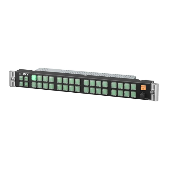
MKS-R3210
Operating instructions manual
Sony MKS-R3210 Operating Instructions Manual
Lcd remote control panel
Hide thumbs
1
Table Of Contents
2
3
4
5
6
7
8
9
10
11
12
13
14
15
16
17
18
19
20
21
22
23
24
25
26
27
28
29
30
31
32
33
34
35
36
37
38
page
of
38
Go
/
38
Contents
Table of Contents
Bookmarks
Table of Contents
Table of Contents
Overview
Features
Button Function Settings
System Connection Example
Locations and Functions of Parts
Front Panel
Rear Panel
Status Display Window (MKS-R1630)
Preparations
Notes on Installation
Setting up the Unit
Connections with System Controllers
Key Label Indications
Configuring Using the Buttons
Operations
Configuring Using a System Controller and Web Menu
Pinned Buttons, Selection Buttons, and Function Buttons
Switching between Source Selection Mode and Destination Selection Mode
Switching Crosspoints
Assigning a Source/Destination to a Selection Button (Assign)
Switching a Different Source for each Level (Breakaway)
Switching Multiple Crosspoints Simultaneously (Salvo)
Take Mode
Pages and Page Groups
Switching and Monitoring Two Sources (Chop)
Preventing Source Switching for Destinations (Protect)
Preventing Accidental Operation (Lock)
Monitoring Destinations
Level Control
Retrace Function
Linkage Function
Web Menu
Displaying the Web Menu
Screen Configuration
Panel Table Page
Source Reentry Lists Page
Salvo Table Page
Available Src/Dest Page
Control Area Page
Alias Name Lists Page
Default Controls Page
Operation Settings Page
Display Settings Page
Retrace Settings Page
Linkage Settings Page
Page Group Settings Page
Network Settings Page
Remote Maintenance Page
Time Settings Page
System Page
Csv
Usage Precautions
Error/Warning Messages
Specifications
Advertisement
Quick Links
1
Table of Contents
2
Button Function Settings
3
Overview
4
System Connection Example
5
Setting up the Unit
6
Configuring Using a System Controller and Web Menu
7
Specifications
Download this manual
4-733-749-14 (1)
32 BUTTON REMOTE CONTROL
PANEL
MKS-R3210
16 BUTTON LCD REMOTE
CONTROL PANEL
MKS-R1620
UNIVERSAL 16 LCD REMOTE
CONTROL PANEL
MKS-R1630
Operating Instructions
© 2017 Sony Corporation
Table of
Contents
Previous
Page
Next
Page
1
2
3
4
5
Advertisement
Table of Contents
Need help?
Do you have a question about the MKS-R3210 and is the answer not in the manual?
Ask a question
Questions and answers
Related Manuals for Sony MKS-R3210
Control Panel Sony MKS-R4020 Operating Instructions Manual
40 lcd button remote control panel, 16 rotary encoder remote control panel (25 pages)
Control Panel Sony MKS-R1620 Operating Instructions Manual
Lcd remote control panel (38 pages)
Control Panel Sony MKS-8010A Installation Manual
Center control panel pack (50 pages)
Control Panel Sony CCP-8000 Installation Manual
Center control panel pack (58 pages)
Control Panel Sony ICP-X7000 Operation Manual
Integrated control panel, system interface unit (40 pages)
Control Panel Sony ICP-X7000 Installation Manual
Integrated control panel (126 pages)
Control Panel Sony MKS-9011A Installation Manual
(38 pages)
Control Panel Sony BKDM-3020 Maintenance Manual
Digital multi effects, dme control panel (78 pages)
Control Panel Sony RCP-3100 Operating Instructions Manual
Remote control panel (24 pages)
Control Panel Sony RCP-1500 Operation Manual
Remote control panel (84 pages)
Control Panel Sony RCP-750 Maintenance Manual
Remote control panel (120 pages)
Control Panel Sony RCP-D50 Service Manual
Remote control panel (152 pages)
Control Panel Sony RCP-1500 Maintenance Manual
Remote control panel (126 pages)
Control Panel Sony MSU-1000 Operation Manual
Master setup unit for recording (2 pages)
Control Panel Sony RCP-TX7 Service Manual
Remote control panel (22 pages)
Control Panel SONY RCP-750 Operation Manual
Remote control panel (60 pages)
This manual is also suitable for:
Mks-r1620
Mks-r1630
Table of Contents
Print
Rename the bookmark
Delete bookmark?
Delete from my manuals?
Login
Sign In
OR
Sign in with Facebook
Sign in with Google
Upload manual
Upload from disk
Upload from URL


Need help?
Do you have a question about the MKS-R3210 and is the answer not in the manual?
Questions and answers