Table of Contents
Advertisement
Quick Links
CoaXPress
Monochrome / Color CMOS Camera
STC-LBGP251BCXP124
(25M / Monochrome / High speed / CXP-12x4 / Connector on rear)
STC-LCGP251BCXP124
(25M / Color / High speed / CXP-12x4 / Connector on rear)
STC-LBGP251BCXP124-T
(25M / Monochrome / High speed / CXP-12x4 / Connector on top)
STC-LCGP251BCXP124-T
(25M / Color / High speed / CXP-12x4 / Connector on top)
Product Specifications and User's Guide
STC-LBGP251BCXP124 / STC-LCGP251BCXP124 / STC-LBGP251BCXP124-T / STC-LCGP251BCXP-T
Product Specifications and User's Guide
No.20S062-00
1/55
Advertisement
Table of Contents

Related Manuals for Omron CoaXPress STC-LBGP251BCXP124


Summary of Contents for Omron CoaXPress STC-LBGP251BCXP124
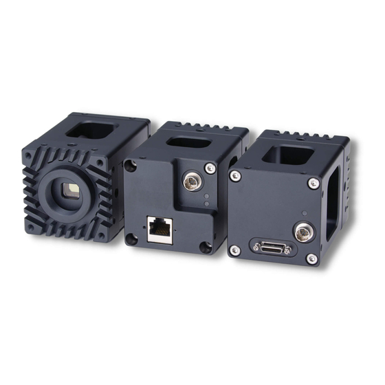
- Page 1 No.20S062-00 CoaXPress Monochrome / Color CMOS Camera STC-LBGP251BCXP124 (25M / Monochrome / High speed / CXP-12x4 / Connector on rear) STC-LCGP251BCXP124 (25M / Color / High speed / CXP-12x4 / Connector on rear) STC-LBGP251BCXP124-T (25M / Monochrome / High speed / CXP-12x4 / Connector on top) STC-LCGP251BCXP124-T (25M / Color / High speed / CXP-12x4 / Connector on top) Product Specifications and User’s Guide...
-
Page 2: Table Of Contents
No.20S062-00 Table of Contents Product Precautions ................................ 7 Product conformity / compliance ........................... 7 Warranty ................................... 7 Overview ................................... 8 Features ..................................8 Product Number Naming Method ..........................8 Specifications .................................. 9 Electronic Specifications............................. 9 Spectral Sensitivity Characteristics ...........................11 Mechanical Specifications ............................12 Environmental Specifications ........................... - Page 3 No.20S062-00 9.14 Multi ROI ................................... 34 9.15 Flat Field Correction Control ............................ 35 9.15.1 FFC function procedure ............................ 36 9.16 Gamma Table ................................37 9.17 Pixel Defect Correction ............................. 38 9.18 Event Control ................................39 9.19 Save and load camera settings ..........................40 9.19.1 Saving the Camera Settings ..........................
- Page 4 No.20S062-00 Precautions for safety Please read carefully this “Precautions for safety” before use the camera. Then the camera uses correctly with agreeing with below notes. In this “Precautions for safety”, notes divides into “Warning” and “Caution” to use the camera safety and prevent to harm and damage.
- Page 5 No.20S062-00 Caution Do not grounding DC power (+) of all devices It is necessary to wiring and mounting that is that are connect to the camera. specified in the specifications for this camera. The camera housing is connecting to 0 V line of This will cause of fire or malfunction.
- Page 6 No.20S062-00 [Disposal] Caution It is necessary to dispose as industrial waste. It is necessary to dispose of accordance with WEEE directive. [Security Measures, Anti-virus protection] Warning Install the latest commercial-quality antivirus software on the computer connected to the control system and maintain to keep the software up-to-date.
-
Page 7: Product Precautions
No.20S062-00 Product Precautions Do not give shock to the camera. Do not haul or damage the camera cable. Do not wrap the camera with any material while using the camera. This will cause the internal camera temperature to increase. ... -
Page 8: Overview
No.20S062-00 Overview This document describes the specifications of the following cameras STC-LBGP251BCXP124 / STC-LCGP251BCXP124 STC-LBGP251BCXP124-T / STC-LCGP251BCXP124-T Features ・CoaXPress (CXP) Interface: CXP-12 / CXP-6 / CXP-3, 4 lane / 2 lane / 1 lane ・PoCXP (Power Over CoaXPress) support ・Maximum frame rate (Full resolution): 150 fps @ 25M 8bits ・CMOS (Global Shutter) ・Up to 2,048 Pixel Defect Correction (Default: ON) ・8bits, 10bits output... -
Page 9: Specifications
No.20S062-00 Specifications Electronic Specifications STC-LBGP251BCXP124 / STC-LCGP251BCXP124 / Model Number STC-LBGP251BCXP124-T STC-LCGP251BCXP124-T 1.1” 25M Progressive Monochrome CMOS 1.1” 25M Progressive Monochrome CMOS Image Sensor (Gpixel: GMAX0505) (Gpixel: GMAX0505) Shutter Type Global Shutter 5,120 (H) x 5,120 (V) Active Picture Elements Cell Size 2.5 (H) x 2.5 (V) µm Scanning System... - Page 10 No.20S062-00 Precautions (*1) When Image Format is changed, ADC bits width also changes. The ADC bits width cannot be changed. Image Format ADC bits width -> Mono8 / BayerRG8 10bits -> Mono10 / BayerRG10 10bits (*2) The pixel format (Bayer pattern) for color model is changed when image is flipping with image flip function. The Bayer pattern in this document is Bayer pattern of image flip function Off.
-
Page 11: Spectral Sensitivity Characteristics
No.20S062-00 Spectral Sensitivity Characteristics STC-LBGP251BCXP124 / STC-LCGP251BCXP124 / STC-LBGP251BCXP124-T / STC-LCGP251BCXP-T 11/55 Product Specifications and User’s Guide... -
Page 12: Mechanical Specifications
No.20S062-00 Mechanical Specifications STC-LBGP251BCXP124 / STC-LBGP251BCXP124-T / Model Number STC-LCGP251BCXP124 STC-LCGP251BCXP124-T Dimensions 68 (W) x 68 (H) x 53.5 (D) mm (*1) Optical Filter No Optical Filter Optical Center Accuracy Positional accuracy in Horizontal and Vertical directions: +/- 0.5 mm Rotational accuracy of Horizontal and Vertical: +/- 1.5 deg. -
Page 13: Environmental Specifications
No.20S062-00 Environmental Specifications Model Number STC-LBGP251BCXP124 STC-LBGP251BCXP124-T STC-LCGP251BCXP124 STC-LCGP251BCXP124-T Operational Minimum Environmental Temperature: 0 deg. C, Temperature / Environmental Humidity: 20 to 85 %RH (No Condensation) Humidity Maximum Environmental Temperature: +37 deg. C or Camera housing temperature (top plate) shall not exceed +60 deg. C (*1) Environmental Humidity: 20 to 85 %RH (No Condensation) Storage Temperature / Environmental Temperature: -20 to +75 deg. -
Page 14: External Connector Specifications
No.20S062-00 External Connector Specifications Micro BNC Micro BNC Connector Connector Power/IO Connector Power/IO Connector STC-LxGP251BCXP124 STC-LxGP251BCXP124-T 5.5.1 Micro BNC Connector Micro BNC, 75 Ohm or equivalent x 4 This camera is PoCXP supported CoaXPress camera. The CoaXPress frame grabber board is supplied power to camera through Micro BNC connector. Please using CXP12 supported cable. -
Page 15: Power/Io Connector
No.20S062-00 5.5.2 Power/IO Connector HR10A-7R-6PB (Hirose) or equivalent. This connector is for external power supply and, input and output signals. As for the cable part (Female connector), HR10A-7P-6S (Hirose) or equivalent can be used. Pin assignment Pin No. Signal Name IN/OUT Signal Voltage Line3... - Page 16 No.20S062-00 ● Block diagram of IO connector Camera IO interface 3.3V 3.3V Recommended interface circuit (FPGA SIDE) 100 Ω 3.3VLVCOMS or LVTTL dir cont (input) INPUT High Level : 2.0V ~ 3.3V INPUT Low Level : 0V ~ 0.8V Nch MOSFET Open Drain 3.3V 3.3V...
-
Page 17: Connector Indicator Lamp
No.20S062-00 5.5.3 Connector indicator lamp Connector indicator LED exists beside of Micro BNC connector. LED informs status of communication. The detail of status is as following table. Status LED Blinking Pattern No power System booting Solid orange Device / Host no connection When using PoCXP: : (No such case) When using external power:... -
Page 18: Dimensions
No.20S062-00 Dimensions STC-LBGP251BCXP124 / STC-LCGP251BCXP124 Unit: mm STC-LBGP251BCXP124 / STC-LCGP251BCXP124 / STC-LBGP251BCXP124-T / STC-LCGP251BCXP-T 18/55 Product Specifications and User’s Guide... -
Page 19: Stc-Lbgp251Bcxp124-T / Stc-Lcgp251Bcxp124-T
No.20S062-00 STC-LBGP251BCXP124-T / STC-LCGP251BCXP124-T Unit: mm STC-LBGP251BCXP124 / STC-LCGP251BCXP124 / STC-LBGP251BCXP124-T / STC-LCGP251BCXP-T 19/55 Product Specifications and User’s Guide... -
Page 20: Sensor Information
No.20S062-00 Sensor Information Pixel Transferring Image STC-LBGP251BCXP124 / STC-LBGP251BCXP124-T (Monochrome) Pixel 1 Pixel 2 of Data of Data Pixel (n) of Data: nth pixel being transferred STC-LCGP251BCXP124 / STC-LCGP251BCXP124-T (Color) Pixel 11 Pixel 12 of Data of Data Pixel 21 Pixel 22 of Data of Data... -
Page 21: Camera Operational Modes
No.20S062-00 Camera Operational Modes Normal Mode Exposure Time Expose Image out STC-LBGP251BCXP124 / STC-LCGP251BCXP124 / STC-LBGP251BCXP124-T / STC-LCGP251BCXP-T 21/55 Product Specifications and User’s Guide... -
Page 22: Edge Preset Trigger Mode
No.20S062-00 Edge Preset Trigger Mode In this trigger mode with positive polarity, the expose starts at rising edge of trigger signal. The exposure duration time is based on preset exposure setting stored by camera setting communication. In this trigger mode with negative polarity, the expose starts at falling edge of trigger signal. The exposure duration time is based on preset exposure setting stored by camera setting communication. -
Page 23: Frame Rate
No.20S062-00 Frame rate The frame rate of camera calculates with below formula with ROI and exposure time settings. ● Formula of frame rate Frame rate [fps] = 1,000,000 / (Number of lines for one frame x 1 H time [usec.]) 1 H time [usec.] = “Hnum”... -
Page 24: The Interval Of Trigger Input
No.20S062-00 The interval of trigger input The minimum interval of trigger input is changed based on trigger overlap setting (TriggerOverlap). The trigger input that does not match minimum interval condition, is invalid. Please refer “Frame rate” section for “Number of sensor frame line” and “1 H time” in this section. The minimum interval of trigger input is possible to check with “Frame Trigger Wait”... -
Page 25: Burst Trigger
No.20S062-00 Burst trigger When selecting the burst trigger (Frame Burst Start) operation, number of images acquiring by one trigger signal with minimum acquisition interval. The number of acquisition images can be set at AcquisitionBurstFrameCount. The another trigger signal input while acquiring images with burst trigger, is invalid. Input trigger signal (Edge preset, positive) Input trigger signal... -
Page 26: Camera Functions
No.20S062-00 Camera Functions This chapter describes the camera functions. CXP Configuration This parameter sets the CoaXPress configuration mode. GenICam Parameters CxpLink IEnumeration Sets CXP configuration mode. Configuration Type CXP12_X4: CXP-12 (12.500Gbps) 4 lane (Default) CXP6_X4: CXP-6 (6.250Gbps) 4 lane CXP3_X4: CXP-3 (3.125Gbps) 4 lane CXP12_X2: CXP-12 (12.500Gbps) 2 lane CXP6_X2: CXP-6 (6.250Gbps) 2 lane CXP3_X2: CXP-3 (3.125Gbps) 2 lane... -
Page 27: Pixel Format
No.20S062-00 Pixel Format This parameter sets the image format from camera can be set on Pixel Format. GenICam Parameters PixelFormat IEnumeration Type Sets Pixel Format. The following chart shows available Pixel Formats on camera: Output Bit Pixel Format Monochrome Color 8bits Mono8 (Default) BayerRG8 (Default) -
Page 28: Trigger
No.20S062-00 Trigger These parameters set operational mode (trigger mode) and trigger type. The selectable trigger types are listed in below table GenICam Parameters TriggerSelector IEnumeration Type Trigger function selection Frame Start: Normal trigger function (Default) Frame Burst Start: Burst trigger function TriggerMode IEnumeration Type Operational mode (trigger mode) selection... -
Page 29: Black Level
No.20S062-00 Black Level This parameter sets the black level (clamp level for black signal). The lower limit of signal is clamped at this setting level. The signal does not lower than this. GenICam Parameters BlackLevel [BlackLevelSelector] IFloat Type Black Level Range: 8bits output: 0 to 31 10bits output: 0 to 127... -
Page 30: White Balance (Only Available For Color Model)
No.20S062-00 9.10 White Balance (Only available for color model) The color compensates by gain adjustment for each individual color. The gain for each color has to adjust to same brightness with flat white target. The white balance control methods are listed in below: GenICam Parameters BalanceWhiteAuto IEnumeration Type... -
Page 31: Binning (Only Available For Monochrome Model)
No.20S062-00 9.11 Binning (Only available for monochrome model) Binning is summing and averaging beside pixels into one pixel. The pixel data inside of red square add or average as one pixel. Binning X (OFF: 1), Y (OFF: 1) Binning X (ON: 2), Y (ON: 2) GenICam Parameters BinningHorizontalMode IEnumeration Type... -
Page 32: Decimation
No.20S062-00 9.12 Decimation When using Decimation mode, decimated image can be output. The images below show decimated pixels (red squares) where they are output. <Monochrome> <Color> Decimation X (OFF), Y (OFF) Decimation X (ON), Y (ON) Decimation X (OFF), Y (OFF) Decimation X (ON), Y (ON) GenICam Parameters DecimationHorizontal... -
Page 33: Roi (Region Of Interest)
No.20S062-00 9.13 ROI (Region of Interest) This sets the ROI in order to output selected area of image. The frame rate increases when reducing height of image. The frame rate does not change when reducing width of image. Please use “Multi ROI” settings when setting multi ROI. When selecting Binning or Decimation function, setting value of Width, Height, OffsetX and OffsetY will be half of full resolution image. -
Page 34: Multi Roi
No.20S062-00 9.14 Multi ROI The maximum eight ROI regions (one horizontal region x eight vertical regions) are configurable. Each region must not overlap other regions. Please set each region (Region0 to 7) from top of image to bottom of image and must not overlap other regions. The width of multi ROI sets at “Width”... -
Page 35: Flat Field Correction Control
No.20S062-00 9.15 Flat Field Correction Control Flat Flied Correction (FFC) function is correcting shading on image that caused by characteristics of lens (amount of through light difference at center and edge of lens) and characteristics of light (uneven brightness level). This function is supported by StViewer in SentechSDK (v1.1.1 or later). -
Page 36: Ffc Function Procedure
No.20S062-00 9.15.1 FFC function procedure FFC function procedure Selects “Start calculating FFC correction values” under “File” on menu at “StViewer”. The FFC correction values calculate automatically. The image stops while FFC correction values are calculating. When FFC correcting values are calculated, sets “True” at “FFC Enable” automatically and FFC function applied image are acquired. -
Page 37: Gamma Table
No.20S062-00 9.16 Gamma Table The linearity of gradient of image can be correct by gamma table on camera. GenICam Parameters Gamma IFloat Type Gamma Range: 0.01 to 4.00, Default: 1.00, Adjustment step: 0.01 Gamma Formula For 10bits image γ γ ... -
Page 38: Pixel Defect Correction
No.20S062-00 9.17 Pixel Defect Correction The defected pixel corrects with horizontally beside pixel information. The defected pixel corrects with horizontally beside same color pixel information for color model. The coordination of defected pixels can be save to camera (UserSetSave) or load from camera (UserSetLoad). When selecting “Default”... -
Page 39: Event Control
No.20S062-00 9.18 Event Control The camera internal signal can be output as specified event information, like “exposure end”, to PC. e.g. Event control Exposure timing Frame timing Event Frame End Event Exposure End Event Frame Start Event Exposure Start GenICam Parameters EventSelector IEnumeration Type Event notification selection... -
Page 40: Save And Load Camera Settings
No.20S062-00 9.19 Save and load camera settings The camera has camera setting save function, camera setting including factory default loads function. The camera has below two camera settings. Default: The factory default settings (This setting cannot change) UserSetX: Over writeable camera settings (X: 0 to 7) Data type Camera settings FFC data... -
Page 41: Loading Camera Settings
No.20S062-00 9.19.2 Loading Camera Settings When UserSetLoad is executing, the camera settings load from selected ROM UserSetX that was selected at “UserSetSelector” to Camera register at RAM. Setting Default Selector UserSetSelector Setting Procedure 1. Select “UserSetX” (or Default) at “UserSetSelector” 2. -
Page 42: Io Function
No.20S062-00 10 IO Function This chapter describes IO functions. In this chapter, the IO Port places as “Line”. The follow chart details relationship of Line and IO Port. IO Port Line number Pin No. Line3 Line2 Line1 Line0 GenICam Parameters LineSelector IEnumeration Type Select Line... -
Page 43: Line Debouncer
No.20S062-00 10.1.3 Line Debouncer Line Debouncer can reduce the wrong input signal detection that is noise on signal or chartering, by filtering input signal. GenICam Parameters LineDebounceTime IInteger Type Line Debounce Time Range: 0 to 10,000 μseconds, Default: 1 μseconds Timing Line Input Line入力信号... -
Page 44: Output Port Function
No.20S062-00 10.2 Output Port Function This function sets the Output to LineMode, and then Line is assigned as output. The following functions can be assigned when IO port is used as output signal port. 10.2.1 LineSource The following list shows the configurable functions available through LineSource. The function that describes as “Enable”... - Page 45 No.20S062-00 11) Exposure Active (In Exposure Period) The signal that activation time is exposure time is output. (*) Actual exposure period = Output signal pulse width + Minimum exposure time 13.73 seconds μ Line Source Timing トリガー入力 Trigger Input 露光 Exposure ReadOut (Sensor to FPGA) リードアウト...
-
Page 46: User Output
No.20S062-00 10.2.2 User Output High or low level signal that was configured on software is output. Setting Procedure Selects LineN (N: any number from 0, 1 or 2) 1) Sets the UserOutputN (N is Line number) as LineSource 2) Selects UserOutputN (N is same as selected Line number on UserOutput) on UserOutputSelector 3) Sets the value (True: High level, False: Low level) on UserOutputValue 10.2.3 LineStatus... -
Page 47: Genicam Command List
No.20S062-00 11 GenICam command list 11.1 DeviceControl Name Description DeviceType Returns the device type. DeviceScanType Scan type of the sensor of the device. DeviceVendorName Name of the manufacturer of the device. DeviceModelName Model of the device. DeviceManufacturerInfo Manufacturer information about the device. DeviceVersion Version of the device. -
Page 48: Imageformatcontrol
No.20S062-00 11.2 ImageFormatControl Name Description SensorWidth Effective width of the sensor in pixels. SensorHeight Effective height of the sensor in pixels. SensorShutterMode Sets the shutter mode of the device. WidthMax Maximum width of the image (in pixels). The dimension is calculated after horizontal binning, decimation or any other function changing the horizontal dimension of the image. -
Page 49: Acquisitioncontrol
No.20S062-00 Name Description TestPatternGeneratorSelector Selects wich test pattern generator is controlled by the TestPattern feature. TestPattern Selects the type of test pattern that is generated by the device as image source. [TestPatternGeneratorSelector] TestPatternInputValue Test Pattern Input Value [TestPatternGeneratorSelector] 11.3 AcquisitionControl Name Description AcquisitionMode... -
Page 50: Transportlayercontrol
No.20S062-00 11.4 TransportLayerControl Name Description PayloadSize Provides the number of bytes transferred for each image or chunk on the stream channel. This includes any end-of-line, end-of-frame statistics or other stamp data. This is the total size of data payload for a data block. CxpLinkConfigurationStatus This feature indicates the current and active link configuration used by the device. -
Page 51: Analogcontrol
No.20S062-00 11.6 AnalogControl Name Description GainSelector Selects which Gain is controlled by the various Gain features. Gain [GainSelector] Controls the selected gain as an absolute physical value. This is an amplification factor applied to the video signal. BlackLevelSelector Selects which Black Level is controlled by the various Black Level features. BlackLevel [BlackLevelSelector] Controls the black level as an absolute physical value. -
Page 52: Event Control
No.20S062-00 11.8 Event Control Name Description EventSelector Selects which Event to signal to the host application. EventNotification [EventSelector] Activate or deactivate the notification to the host application of the occurrence of the selected Event. EventExposureStart Returns the unique Identifier of the Exposure Start type of Event. EventExposureStartTimestamp Returns the Timestamp of the Exposure Start Event. -
Page 53: Flatfieldcorrectioncontrol
No.20S062-00 11.10 FlatFieldCorrectionControl Name Description FFCSelector Selects which Correction is controlled by the FFC features. FFCType Returns the FFC Type. FFCMeshWidth Returns the Width of every mesh area for FFC table. FFCMeshHeight Returns the Height of every mesh area for FFC table. FFCEnable Activates the selected FFC. -
Page 54: Revision History
No.20S062-00 12 Revision History Date Changes Note 2022/08/30 New Document Note: Product specifications would be changed without notification. CoaXPress is registered trademarks of JIIA (Japan Industrial Imaging Association) GenICam is trademark of EMVA. Other company names and product names in this document are trademarks of their respective owners. STC-LBGP251BCXP124 / STC-LCGP251BCXP124 / STC-LBGP251BCXP124-T / STC-LCGP251BCXP-T 54/55 Product Specifications and User’s Guide... - Page 55 No.20S062-00 19F, Ebina Prime Tower 9-50, Chuo 2 chome Ebina-city, Kanagawa 243-0432 Japan TEL +81-46-236-6660 FAX +81-46-236-6661 URL http://www.sentech.co.jp/ STC-LBGP251BCXP124 / STC-LCGP251BCXP124 / STC-LBGP251BCXP124-T / STC-LCGP251BCXP-T 55/55 Product Specifications and User’s Guide...
Need help?
Do you have a question about the CoaXPress STC-LBGP251BCXP124 and is the answer not in the manual?
Questions and answers