Table of Contents
Advertisement
Quick Links
Advertisement
Table of Contents

Related Manuals for DFI GM341-GHF


Summary of Contents for DFI GM341-GHF
- Page 1 GM341-GHF Gaming Computing System User’s Manual A50110941...
- Page 2 The changes or modifications not expressly approved by the party responsible for compli- are the properties of the respective owners. ance could void the user’s authority to operate the equipment. Shielded interface cables must be used in order to comply with the emission limits. User's Manual | GM341-GHF...
-
Page 3: Table Of Contents
Key Features ................6 5V DC-out ................25 Specifications ................7 Chapter 6 - Mounting ....... 26 Getting to Know the GM341-GHF ..........8 Chapter 7 - BIOS Setup ......27 Mechanical Dimensions ............9 Chassis Dimension ..............9 Chapter 8 - Supported Software ....42 Chapter 3 - Installing Devices .... -
Page 4: About This Manual
About this Manual Static Electricity Precautions An electronic file of this manual can be obtained from the DFI website at www.dfi.com. To It is easy to inadvertently damage your PC, system board, components or devices even before download the user’s manual from our website, please go to Support > Download Center. On installing them in your system unit. -
Page 5: Safety Precautions
• Unplug the power cord before removing the system chassis cover for installation or servic- ing. After installation or servicing, cover the system chassis before plugging the power cord. • GM341-GHF system unit • Mounting screws for M.2 modules • Danger of explosion if battery incorrectly replaced. -
Page 6: Chapter 1 - Introduction
Two LAN ports One RS-232 (DB-9 connector) One RS-232/422/485 (DB-9 connector) One RS-232 (Tx, Rx)/ccTalk (pin headers) Two RS-232 (Tx, Rx)/SAS/BACTA (pin headers) Four DP Display Two USB 3.0 and four USB 2.0 Type A ports User's Manual | GM341-GHF... -
Page 7: Specifications
• 270mm x 63mm x 210mm (10.63" x 2.48" x 8.27") Weight • TBD OS Support Windows 10 (64-bit) Ubuntu 16.04LTS (64-bit) Note: *The mount kit is not supported in the standard model. Please contact your sales representative for more information. User's Manual | GM341-GHF... -
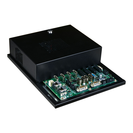
Page 8: Getting To Know The Gm341-Ghf
Chapter 1 Chapter 1 Getting to Know the GM341-GHF Front View Speaker and 5.1 ch audio Connects an audio I/O module to the 4-pin speaker connector for stereo (10W+10W) speak- ers and 5.1 ch audio connector for audio sound systems; there is also an S/PDIF digital audio connector. -
Page 9: Mechanical Dimensions
Chapter 1 Mechanical Dimensions Chassis Dimension Front View Left View Right View Top View 63.00 67.00 Rear View 270.00 User's Manual | GM341-GHF... - Page 10 Please refer to your operating system manual for instructions on installing an operating system. Installing the Drivers The system comes with a software package including drivers. These drivers must be installed to provide the best system performance. Refer to the Supported Software Chapter for instructions on installing drivers. User's Manual | GM341-GHF...
-
Page 11: Chapter 3 - Installing Devices
The tact buttons on the I/O board can be used to invoke a door intrusion event or set the high/low level of a digital I/O port. You can also use the demonstration application to alter a digital I/O port’s level. For more information, please refer to the software ap- plication guide. User's Manual | GM341-GHF... -
Page 12: Removing The Chassis Cover
Mounting screw SODIMM modules Notes: The system supports dual-channel configuration. To enable dual-channel, populate both SODIMM sockets. The SODIMM sockets can only accept DDR4 (3200MHz) memory modules. Please do not install other types of memory modules. User's Manual | GM341-GHF... -
Page 13: Installing An M.2 Card
2-pin 5V/2A DC-out connector. Align the SATA port with the connector of a SATA DOM before inserting the SATA DOM. one) to secure both cards on the system board. M.2 module User's Manual | GM341-GHF... -
Page 14: Chapter 4 - Jumper Settings
2. Set the jumper pins 2 and 3 to On. Wait for a few seconds and set the jumper back to its default setting, pins 1 and 2 On. 3. Now plug the power cord and power-on the system. User's Manual | GM341-GHF... -
Page 15: Mcu Programming Mode
Door 1~6 1-2 On: None: F.W. update programmable Protective mode J15 is used to select the MCU programming mode. To enable or disable MCU programming of the system board, please set the jumper as indicated above. User's Manual | GM341-GHF... -
Page 16: Chapter 5 - Ports And Connectors
> “NB Azalia”) of the BIOS. Refer to Chapter 7 for more information. • Driver Installation You may need to install audio driver in your operating system to use audio devices. Refer to Chapter 8 and your operating system’s documentation for more information. User's Manual | GM341-GHF... -
Page 17: Usb Ports
Configure the COM ports including its communication mode in the "Advanced" menu (“USB Con- Assignment Assignment figuration” and "SB USB Configuration" under the "CPU" menu) of the BIOS. Refer to Chapter 7 for more information. GND 1 12V1 GND 2 12V2 User's Manual | GM341-GHF... -
Page 18: Com Ports
• BIOS Setting Configure the COM ports including its communication mode in the "Advanced" menu (“NCT6116D Super IO Configuration” submenu) and ("Serial Port Console Redirection" submenu) of the BIOS. Refer to Chapter 7 for more information. User's Manual | GM341-GHF... -
Page 19: Rj45 Lan Ports
API utility provides logging functions for recording up to a total of 64 entries. Driver Installation Software The software package that came with the system contains application and code samples to Install the LAN drivers. Refer to Chapter 8 for more information. implement door intrusion alarms for the system. User's Manual | GM341-GHF... -
Page 20: Display Outputs
Install the AMD Radeon™ graphics driver and software. Please refer to Chapter 8 for more DI 9 / DI 25 DO 8 / DO 24 ® information. DI 10 / DI 26 DO 9 / DO 25 User's Manual | GM341-GHF... - Page 21 I/O pins. The GPIO Control API of the GamingLogic API utility allows you to control the digital input/output pins. Please contact your sales representative for the gaming software package. Driver Installation Install the Windows WinDriver. Please refer to Chapter 8 for more information. User's Manual | GM341-GHF...
-
Page 22: Expansion Connectors
NVMe SSDs. It can be inserted with an M.2 (NGFF) card with the form factor of 22x80 mm. BIOS Setting The Advanced menu (“ NCT6116D HW Monitor ” submenu) of the BIOS will display the current speed of the cooling fans. Refer to the Chapter 7 for more information. User's Manual | GM341-GHF... -
Page 23: Leds
This LED will be red when there is power on the system board. • Dispose of used batteries according to local ordinance Software The software package that came with the system contains application and code samples to implement voltage monitoring and alarms for the system. User's Manual | GM341-GHF... -
Page 24: Sata (Serial Ata) Connectors
L_CLK L_AD1 Configure the Serial ATA drives in the Advanced menu ("AMD CHIPSET Setting" > “SATA Con- L_RST# L_AD0 figuration Options”) of the BIOS. Refer to Chapter 7 for more information. L_FRAME# L_AD3 L_AD2 INT_SERIRQ 5VSB User's Manual | GM341-GHF... -
Page 25: 5V Dc-Out
DO 1~16 5.1CH M.2 2280 (M Key) DO 17~32 Only for the V1000 CPU BAT 1 Intrusion Intrusion S/PDIF iButton Door7 USB 3.0_1 Door 1~6 +5V DC power_out The 2-pin connector provides low power output of 5V/2A. User's Manual | GM341-GHF... -
Page 26: Chapter 6 - Mounting
Drill 4 holes in the wall and insert screw bolts into the holes. Drill the screws into the screw anchors. Hang the device on the wall. The diagram on the right shows the screw holes and dimensions of wall mount (in millimeter). Screw hole Screw hole User's Manual | GM341-GHF... -
Page 27: Chapter 7 - Bios Setup
To display the submenu, move the highlight to disappears before you respond, restart the system or press the “Reset” button. You may also that field and press <Enter>. restart the system by pressing the <Ctrl> <Alt> and <Del> keys simultaneously. User's Manual | GM341-GHF... - Page 28 The time format is <hour>, <minute>, <second>. The time is based on the 24-hour military-time clock. For example, 1 p.m. is 13:00:00. Hour displays hours from 00 to 23. Minute displays minutes from 00 to 59. Second displays seconds from 00 to 59. User's Manual | GM341-GHF...
- Page 29 This option only appears if you choose to specify the UMA mode. Configure the UMA frame buffer size with these options: Auto, 64M, 128M, 256M, 384M, 512M, 1G, or 2G. NB Azalia Automatically configure the integrated high-definition audio controller or disable it. User's Manual | GM341-GHF...
- Page 30 USB2_1 USB2_2 USB2_3 USB2_4 Enable, disable or automatically configure the SATA controller. Enable or disable each USB 2.0 port. SATA Port 1 USB3_1 USB3_2 Enable or disable each SATA port. Enable or disable each USB 3.0 port. User's Manual | GM341-GHF...
- Page 31 Input any value between 0 and 23. Pending Operation Wake up minute Input any value between 0 and 59. Schedule an operation for the security device. Wake up second Input any value between 0 and 59. User's Manual | GM341-GHF...
- Page 32 Enable or disable the generation of ACPI PPC, PSS, and PCT objects. These objects are associated with the operation of CPU P-state. NX Mode Enable or disable the non-execute page protection function. SVM Mode Enable or disable the CPU virtualization function. User's Manual | GM341-GHF...
- Page 33 WDT. Input any value between 1 to 255 in the “SuperIO WatchDog Timer” field. Bits per second: 115200, 57600, 38400, 19200 or 9600. Data bits: 8 bits or 7 bits. Parity: None, Even or Odd. Stop bits: 1 bit or 2 bits. Flow control: None or Hardware RTS/CTS. User's Manual | GM341-GHF...
- Page 34 Configure the serial port mode. The settings are RS232, RS422 and RS485 for Serial Port 1, and RS232 and CC-TALK for Serial Port 3. RS485 Auto Flow Enable or disable the auto flow mechanism for COM Port 1. User's Manual | GM341-GHF...
- Page 35 This is a workaround for OSes that do not support eXtensible Host Controller Interface (xHCI) hand-off. The xHCI ownership change should be claimed by the xHCI driver. USB Mass Storage Driver Support Enable or disable the support for the USB Mass Storage Driver. User's Manual | GM341-GHF...
- Page 36 Enter the number of times the presence of media will be checked. Valid range is Note: from 1 to 50 times. When Secure Boot (please refer to "Security"> "Secure Boot" later in this chapter) is enabled, execution of the CSM and legacy ROMs are not allowed. User's Manual | GM341-GHF...
- Page 37 Enter to set a new or change the existing administrator password. User Password Enter to set a new or change the existing user password. Please note that passwords must be at least 3 and up to 20 characters long. User's Manual | GM341-GHF...
- Page 38 Select "Yes" to force the system to use the factory defaults settings. It will set the system to be in the "User Mode". It will also configure the NVRAM to contain pre-defined factory default Secure Boot keys. User's Manual | GM341-GHF...
- Page 39 Select "Yes" to delete all UEFI Secure Boot key stored in the NVRAM. It will also revert the system back to the Setup Mode. Export Secure Boot Variables Export the NVRAM content of Secure Boot configurations to a file in the root folder of a selected file system device. User's Manual | GM341-GHF...
- Page 40 Enable or disable the quiet boot function to configure the screen’s display between POST messages or the OEM logo at bootup. Select Disabled to display the POST messages and select Enabled to display the OEM logo. User's Manual | GM341-GHF...
- Page 41 BIOS file and the firmware update utility. For instructions on how to update BIOS with the flash utility, please see https://www.dfi.com/ tw/knowledge/video/5 from the Knowledge Base of the DFI website. C:\AFU\AFUDOS>afudos filename /B /P /N +--------------------------------------------------------------------------------------------------------+ AMI Firmware Update Utility(APTIO) v2.25 Copyright (C)2008 American Megatrends Inc.
-
Page 42: Chapter 8 - Supported Software
Chapter 8 - Supported Software The system requires you to install drivers for some devices to operate properly. To download the latest driver, please go to the DFI Download Center: http://www.dfi.com/DownloadCenter Once you are in the Download Center page, select your product or type the model name and click “Search”... - Page 43 4. Please wait while the software and drivers are being installed. 2. Choose between “Express Install” or “Custom Install”. The “Express Install” installs all the programs in the default folder. 5. Once the Radeon ™ Software has been successfully installed, choose “Restart Now”. User's Manual | GM341-GHF...
- Page 44 LAN Driver folder. After the software package has done preparing the software package, click “Next” to continue. 2. Click “Install” to start the installation. 3. Click “Finish” to exit the wizard after the installation is complete. User's Manual | GM341-GHF...
- Page 45 1. Setup is now ready to install WinDriver USB/PCI Version 12.3.0. Click “Next” to continue. 4. Please wait while the Setup is installing the driver. 2. Read the license agreement then click “Yes” to continue. 5. Click “Finish” to exit the Setup wizard. User's Manual | GM341-GHF...
Need help?
Do you have a question about the GM341-GHF and is the answer not in the manual?
Questions and answers