
Related Manuals for DFI CM960-B


Summary of Contents for DFI CM960-B
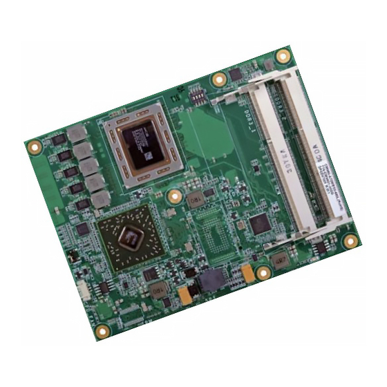
- Page 1 CM960-B COM Express Basic Module User’s Manual A32100420 Chapter 1 Introduction www.dfi .com...
-
Page 2: Copyright
Copyright FCC and DOC Statement on Class B This publication contains information that is protected by copyright. No part of it may be re- This equipment has been tested and found to comply with the limits for a Class B digital produced in any form or by any means or used to make any transformation/adaptation without device, pursuant to Part 15 of the FCC rules. -
Page 3: Table Of Contents
COM Express Connectors ................14 COM Express connector Signal Discription ............ 16 Standby Power LED ................... 26 Cooling Option .................... 26 Installing CM960-B onto a Carrier Board ..........27 Installing the COM Express Debug Card ..........30 Chapter 1 Introduction www.dfi .com... -
Page 4: About This Manual
About this Manual Static Electricity Precautions An electronic file of this manual is included in the CD. To view the user’s manual in the CD, It is quite easy to inadvertently damage your PC, system board, components or devices even insert the CD into a CD-ROM drive. -
Page 5: About The Package
About the Package The package contains the following items. If any of these items are missing or damaged, please contact your dealer or sales representative for assistance. • One CM960-B board • One DVD • One QR (Quick Reference) Optional Items •... -
Page 6: Chapter 1 - Introduction
Chapter 1 Chapter 1 - Introduction Watchdog • Watchdog timeout programmable via software from 1 to 255 seconds Specifications Timer SSD (optional) • 2GB/4GB/8GB/16GB/32GB/64GB • Write: 30MB/sec (max), Read: 70MB/sec (max) ® Processor • AMD Embedded R-Series APUs • SATA to SSD onboard ®... -
Page 7: Features
Chapter 1 Features • Watchdog Timer The Watchdog Timer function allows your application to regularly “clear” the system at the set time interval. If the system hangs or fails to function, it will reset at the set time interval so that your system will continue to operate. -
Page 8: Chapter 2 - Concept
Chapter 2 - Concept COM Express Module Standards The figure below shows the dimensions of the different types of COM Express modules. CM960-B is a COM Express Basic module. The dimension is 95mm x 125mm. Common for all Form Factors Extended only... -
Page 9: Specification Comparison Table
Chapter 2 Specification Comparison Table The table below shows the COM Express standard specifications and the corresponding specifications supported on the CM960-B module. COM Express Module Base DFI CM960-B COM Express Module Base DFI CM960-B Specification Type 6 Type 6... -
Page 10: Chapter 3 - Hardware Installation
Chapter 3 Chapter 3 - Hardware Installation Block Diagram Board Layout LVDS Panel LVDS (Dual Channel) DDI Port 2 Select (SW1) 2 3 4 DP to LVDS Processor TRANSLATOR 800~1600MT/s CH7511B CORE CORE CORE CORE UNBUFFERED DDR3 SODIMM 2x R-Series DISPLAY Port AMD Embedded PCIe GEN2 x8... -
Page 11: Mechanical Diagram
Chapter 3 Mechanical Diagram CM960-B Module with Heat Sink CM960-B Module 53.00 125.00 95.00 91.00 91.00 Top View 49.34 15.44 4.00 4.00 0.00 Heatsink Heatspreader Module PCB Bottom View Standoff Side View of the Module with Heat Spreader, Heat Sink, Fan and Carrier Board 18.08... -
Page 12: System Memory
Chapter 3 Important: Electrostatic discharge (ESD) can damage your board, processor, disk drives, add-in boards, and other components. Perform installation procedures at an ESD workstation only. If such a station is not available, you can provide some ESD protection by wear- ing an antistatic wrist strap and attaching it to a metal part of the system chassis. -
Page 13: Installing The Dimm Module
Chapter 3 Installing the DIMM Module 5. Grasping the module by its edges, align the module into the socket at an approximately 30 degrees angle. Apply firm even pressure to each end of the module until it slips down into the socket. -
Page 14: Connectors
Chapter 3 Connectors COM Express Connectors The COM Express connectors are used to interface the CM960-B COM Express board to a car- CPU Fan Connector rier board. Connect the COM Express connectors (located on the solder side of the board) to the COM Express connectors on the carrier board. - Page 15 Chapter 3 COM Express Connectors RowA RowB RowA RowB RowC RowD RowC RowD GND (FIXED) GND (FIXED) PCIE_TX4- PCIE_RX4- GND (FIXED) GND (FIXED) PEG_RX1- PEG_TX1- GBE0_MDI3- GBE0_ACT# GPO2 TYPE1# TYPE2# GBE0_MDI3+ LPC_FRAME# PCIE_TX3+ PCIE_RX3+ USB_SSRX0- USB_SSTX0- PEG_RX2+ PEG_TX2+ GBE0_LINK100# LPC_AD0 PCIE_TX3- PCIE_RX3- USB_SSRX0+...
-
Page 16: Com Express Connector Signal Discription
I/O Bi-directional input / output signal OD Open drain output AC97/HDA Signals Descriptions Signal Pin# Pin Type Pwr Rail /Tolerance CM960-B Carrier Board Description AC/HAD_RST# O CMOS 3.3V Suspend/3.3V Connect to CODEC pin 11 RESET# Reset output to CODEC, active low. - Page 17 Chapter 3 PCI Express Lanes Signals Descriptions Signal Pin# Pin Type Pwr Rail /Tolerance CM960-B Carrier Board Description PCIE_TX0+ AC Coupling capacitor O PCIE AC coupled on Module Connect to PCIE device or slot PCI Express Differential Transmit Pairs 0...
- Page 18 Chapter 3 PEG Signals Descriptions Signal Pin# Pin Type Pwr Rail /Tolerance CM960-B Carrier Board Description PEG_TX6+ AC Coupling capacitor O PCIE AC coupled on Module Connect to PCIE device or slot PCI Express Graphics transmit differential pairs 6 PEG_TX6-...
- Page 19 Chapter 3 DDI Signals Descriptions Signal Pin# Pin Type Pwr Rail /Tolerance CM960-B Carrier Board Description DDI1_PAIR0+/SDVO1_RED+ Connect AC Coupling Capacitors 0.1uF to Device O PCIE AC coupled off Module DDI 1 Pair 0 differential pairs/Serial Digital Video B red output differential pair DDI1_PAIR0-/SDVO1_RED- Connect AC Coupling Capacitors 0.1uF to Device...
- Page 20 Chapter 3 DDI Signals Descriptions Signal Pin# Pin Type Pwr Rail /Tolerance CM960-B Carrier Board Description DDI2_HPD I CMOS 3.3V / 3.3V PD 1M and Connect to device Hot Plug Detect DDI Hot-Plug Detect Selects the function of DDI2_CTRLCLK_AUX+ and DDI2_CTRLDATA_AUX-.
- Page 21 I/O USB 3.3V Suspend/3.3V and ESD suppressors to GND to USB connector Module designer's discretion.(CM960-B default set as a host) USB7- USB over-current sense, USB channels 0 and 1. A pull-up for this line shall be present on the Module. An open drain driver from a USB...
- Page 22 Chapter 3 USB Signals Descriptions Signal Pin# Pin Type Pwr Rail /Tolerance CM960-B Carrier Board Description USB_SSRX1+ Connect 90 @100MHz Common Choke in series I PCIE AC coupled off Module Additional receive signal differential pairs for the SuperSpeed USB data path.
- Page 23 Chapter 3 LPC Signals Descriptions Signal Pin# Pin Type Pwr Rail /Tolerance CM960-B Carrier Board Description LPC_AD0 LPC_AD1 I/O CMOS 3.3V / 3.3V LPC multiplexed address, command and data bus LPC_AD2 LPC_AD3 LPC_FRAME# O CMOS 3.3V / 3.3V Connect to LPC device...
- Page 24 Chapter 3 Miscellaneous Signal Descriptions Signal Pin# Pin Type Pwr Rail /Tolerance CM960-B Carrier Board Description I2C_CK I/O OD CMOS 3.3V Suspend/3.3V PU 2.2K to 3.3VSB General purpose I2C port clock output I2C_DAT I/O OD CMOS 3.3V Suspend/3.3V PU 2.2K to 3.3VSB General purpose I2C port data I/O line Output for audio enunciator - the "speaker"...
- Page 25 Chapter 3 GPIO Signals Descriptions Signal Pin# Pin Type Pwr Rail /Tolerance CM960-B Carrier Board Description GPO0 GPO1 O CMOS 3.3V / 3.3V General purpose output pins. GPO2 GPO3 GPI0 PU 100K to 3.3V GPI1 PU 100K to 3.3V I CMOS 3.3V / 3.3V...
-
Page 26: Standby Power Led
Bottom View of the Heat Sink • “1” and “2” denote the locations of the thermal pads designed to contact the corresponding components that are on CM960-B. Important: Remove the plastic covering from the thermal pads prior to mounting the heat sink onto CM960-B. -
Page 27: Installing Cm960-B Onto A Carrier Board
The carrier board (COM331-B) used in this section is for reference purpose only and may not resemble your carrier board. These illustrations are mainly to guide you on how to install CM960-B onto the carrier board of your choice. Mounting hole •... - Page 28 5. The photo below shows the solder side of the board with the screws already fixed in place. 7. Position the heat sink on the top of CM960-B with the heat sink’s mounting holes aligned with CM960-B mounting holes. Insert one of the provided long screws into the mounting hole shown in the photo below.
- Page 29 The photo below shows the locations of the long mounting screws. 9. Grasping CM960-B by its edges, position it on the top of the carrier board with its mounting holes aligned with the bolts on the carrier board. This will also align the COM Express connectors of the two boards to each other.
-
Page 30: Installing The Com Express Debug Card
Chapter 3 Installing the COM Express Debug Card 2. Connect the COMe-DEBUG card to COMe-LINK1 via a cable. COMe-DEBUG Note: The system board used in the following illustrations may not resemble the actual board. These illustrations are for reference only. Code Review 80 Port Display Control... - Page 31 Chapter 3 3. Fasten bolts with mounting screws through mounting holes to be fixed in place. 5. Align the mounting hole on the heat sink with the mounting hole on the module and secure the heat sink onto the module by a mounting screw from the bottom side of the module.
- Page 32 Chapter 3 6. Grasp CM960-B with the heat sink by its edges and position them down firmly on the top of the COMe-LINK1 debug card. Cable COM Express Module COMe-LINK1 Carrier Board Side View of the Module, Debug Card and Carrier Board COMe-DEBUG 7.
-
Page 33: Chapter 4 - Bios Setup
Chapter 4 Chapter 4 - BIOS Setup Legends Overview KEYs Function The BIOS is a program that takes care of the basic level of communication between the CPU and peripherals. It contains codes for various advanced features found in this system board. Right and Left Arrows Moves the highlight left or right to select a The BIOS allows you to configure the system and save the configuration in a battery-backed... -
Page 34: Ami Bios Setup Utility
Total Memory 4096 MB (DDR3) ACPI Settings System ACPI Parameters. Trusted Computing System Language [English] DFI Wakeup Confi guration PC Health Status System Date [Mon 01/10/2011] CPU Confi guration System Time [03:53:04] ... - Page 35 Chapter 4 ACPI Settings Trusted Computing This section is used to configure system ACPI parameters. This section configures settings relevant to Trusted Computing innovations. Aptio Setup Utility - Copyright (C) 2012 American Megatrends, Inc. Aptio Setup Utility - Copyright (C) 2012American Megatrends, Inc. Advanced Advanced Confi...
- Page 36 Chapter 4 DFI Wakeup Configuration PC Health Status This section is used to configure the DFI wakeup ACPI power management. This section displays the hardware health monitor. Aptio Setup Utility - Copyright (C) 2012 American Megatrends, Inc. Aptio Setup Utility - Copyright (C) 2012 American Megatrends, Inc.
- Page 37 Chapter 4 CPU Configuration Node 0 Information This section is used to configure the CPU. It will also display the detected CPU information. This field views the memory information which is related to Node 0. Aptio Setup Utility - Copyright (C) 2012 American Megatrends, Inc. Aptio Setup Utility - Copyright (C) 2012 American Megatrends, Inc.
- Page 38 Chapter 4 DDR3 Voltage Setting IDE Configuration This section is used to configure the DDR3 Voltage Setting. This section is used to configure IDE devices. Aptio Setup Utility - Copyright (C) 2012 American Megatrends, Inc. Aptio Setup Utility - Copyright (C) 2012 American Megatrends, Inc. Advanced Advanced IDE Confi...
- Page 39 Chapter 4 USB Configuration Onboard VGA Setting This section is used to configure USB parameters. This section displays the onboard VGA setting. Aptio Setup Utility - Copyright (C) 2012 American Megatrends, Inc. Aptio Setup Utility - Copyright (C) 2012 American Megatrends, Inc. Advanced Advanced Display Port3 TO VGA Mode...
- Page 40 Chapter 4 Network Stack Ipv4 PXE Support Enables the Ipv4 PXE boot support. When disabled, Ipv4 PXE boot option will not be This section configures settings relevant to the network stack. created. Ipv6 PXE Support Aptio Setup Utility - Copyright (C) 2012 American Megatrends, Inc. Advanced Enables the Ipv6 PXE boot support.
- Page 41 This field is used to enable or disable the IT8518 Watchdog Timer function. Blink LEDs for the specified duration (up to 15 seconds). WatchDog 1 function Link Status For CM960-B module board (Reset CM960-B by hardware). This field indicates the link status of the network device. WatchDog 2 function Alternate MAC Address For carrier board usage.
-
Page 42: Chipset
Chapter 4 Chipset NIC Configuration This field is used to configure the network device. This section configures relevant chipset functions. Aptio Setup Utility - Copyright (C) 2012 American Megatrends, Inc. Aptio Setup Utility - Copyright (C) 2012 American Megatrends, Inc. Advanced Main Advanced... - Page 43 Chapter 4 South Bridge SB SATA Configuration This section configures the south bridge parameters. Aptio Setup Utility - Copyright (C) 2012 American Megatrends, Inc. Aptio Setup Utility - Copyright (C) 2012 American Megatrends, Inc. Chipset Chipset OnChip SATA Channel [Enabled] AMD Reference Code Version: Richland PI 1.0.0.3 Options for SATA Conigu-...
- Page 44 Chapter 4 SB USB Configuration SB HD Azalia Configuration Aptio Setup Utility - Copyright (C) 2012 American Megatrends, Inc. Aptio Setup Utility - Copyright (C) 2012 American Megatrends, Inc. Chipset Chipset HD Audio Azalia Device [Enabled] XHCI Controller 0 [Enabled] XHCI ENABLE help.
- Page 45 Chapter 4 GFX Configuration North Bridge Aptio Setup Utility - Copyright (C) 2012 American Megatrends, Inc. Aptio Setup Utility - Copyright (C) 2012 American Megatrends, Inc. Chipset Chipset GFX Confi guration Select Primary Video North Bridge Confi guration Memory Confi guration. Device that BIOS will Primary Video Device [NB PCIe slot Video]...
- Page 46 Chapter 4 Memory Configuration Socket 0 Information Aptio Setup Utility - Copyright (C) 2012 American Megatrends, Inc. Aptio Setup Utility - Copyright (C) 2012 American Megatrends, Inc. Chipset Chipset Memory Confi guration Memory Hole Remapping Socket 0 Information Memory Hole Remapping [Enabled] Starting Address: 0 KB Ending Address: 4194303 KB...
-
Page 47: Boot
Chapter 4 Boot CSM Parameters Aptio Setup Utility - Copyright (C) 2012 American Megatrends, Inc. Aptio Setup Utility - Copyright (C) 2012 American Megatrends, Inc. Main Advanced Chipset Boot Security Save & Exit Main Advanced Chipset Boot Security Save & Exit Launch CSM [Enabled] This option controls if... -
Page 48: Security
Chapter 4 Security Save & Exit Aptio Setup Utility - Copyright (C) 2012 American Megatrends, Inc. Aptio Setup Utility - Copyright (C) 2012 American Megatrends, Inc. Main Advanced Chipset Boot Security Save & Exit Main Advanced Chipset Boot Security Save & Exit Password Description Set Administrator Save Changes and Reset... -
Page 49: Updating The Bios
Chapter 4 Updating the BIOS Save as User Defaults To save changes done so far as user default, select this field and then press <Enter>. To update the BIOS, you will need the new BIOS file and a flash utility, AFUDOS.EXE. A dialog box will appear. -
Page 50: Chapter 5 - Supported Software
Chapter 5 Chapter 5 - Supported Software For Windows 7 The CD that came with the system board contains drivers, utilities and software applications required to enhance the performance of the system board. Insert the CD into a CD-ROM drive. The autorun screen (Mainboard Utility CD) will appear. If after inserting the CD, “Autorun”... - Page 51 Chapter 5 For Windows XP AMD Embedded GPU and Chipset Software Installation Utility To install the driver, click “AMD Embedded GPU and Chipset Software Installation Utility” on the main menu. 1. Under the Language Sup- port section, select the language you would like the installation to display and then click Next.
- Page 52 Chapter 5 Intel LAN Driver (For Windows 7 and 8) 3. Click Express and then click Next. To install the driver, click “Intel LAN Driver” on the main menu. 1. Setup is ready to install the driver. Click Install Drivers and Sofeware. 2.
- Page 53 Chapter 5 Intel LAN Driver (For Windows XP) 4. Select the program featuers you want installed then click Next. To install the driver, click “Intel LAN Driver” on the main menu. 1. Read the user license agreement and click “Accept“. 5.
- Page 54 Chapter 5 4. Click “No, not this time“ in order 7. Click “Continue Anyway“ to con- not to connect to Windows Update tinue the installation. and press “Next“ to continue the installation. 5. Click “Install from a list or specific location“...
- Page 55 Chapter 5 Realtek Audio Driver (optional) AMD RAIDXpert To install the driver, click “Realtek Audio Driver (optional)” on the main menu To install the driver, click “AMD RAIDXpert” on the main menu. 1. Under the Language Sup- port section, select the 1.
- Page 56 Chapter 5 4. Click Next to install or click 7. Click Finish to exit installation. Browse to select another folder. 5. Click External Http Security and then click Next. 6. Click Install to begin installation. Chapter 5 Supported Software www.dfi .com...
- Page 57 Chapter 5 F6 Floppy TPM Driver and Tools (optional) This is used to create a floppy driver diskette needed when you install Windows® XP using To install the driver, click “Infineon TPM driver and tool (optional)” on the main menu. the F6 installation method.
- Page 58 Chapter 5 4. Enter the necessary information 7. The setup program is currently and then click Next. installing the software. 8. Click Finish. 5. Select a setup type and then click Next. 6. Click Install. Chapter 5 Supported Software www.dfi .com...
- Page 59 Chapter 5 Microsoft Framework 3.5 (For Windows XP) 3. Click Exit. Note: Before installing Microsoft .NET Framework 3.5, make sure you have updated your Windows XP operating system to Service Pack 3. To install the driver, click “Microsoft .NET Framework 3.5” on the main menu. 1.
- Page 60 DFI Utility To install the utility, click “Microsoft DirectX 9.0C Driver” on the main menu. DFI Utility provides information about the board, HW Health, Watchdog, DIO, and Backlight. To access the utility, click “DFI Utility” on the main menu. 1. Click “I accept the Note: agreement”...
- Page 61 Chapter 5 3. Enter “User Name” and “Organi- The DFI Utility icon will appear on the desktop. Double-click the icon to open the utility. zation” information and then click Next 4. Click Install to begin the installation. Information 5. After completing installation, click Finish.
- Page 62 Chapter 5 WatchDog Backlight Chapter 5 Supported Software www.dfi .com...
- Page 63 Chapter 5 Adobe Acrobat Reader 9.3 To install the reader, click “Adobe Acrobat Reader 9.3” on the main menu. 1. Click Next to install or click Change Destination Folder to select another folder. 2. Click Install to begin installation. 3. Click Finish to exit installation. Chapter 5 Supported Software www.dfi...
-
Page 64: Chapter 6 - Gpio Programming Guide
Chapter 6 Chapter 6 - GPIO Programming Guide Function Description Get_EC_Data (unsigned char ucData): Read a Byte data from EC. Write_EC_Data (unsigned char ucData, unsigned char Data): Write a Byte data to EC. Sample Code GPIO Input Process EC_DIO_Read_Input() BYTE Data; //Pin0-3 Input Mode Data = Get_EC_Data(0xBA);... -
Page 65: Appendix A - Nlite And Ahci Installation Guide
Appendix A Appendix A - NLITE and AHCI Installation Guide 4. Insert the XP installation disc into an optical drive. nLite 5. Launch nLite. The Welcome screen will appear. Click nLite is an application program that allows you to customize your XP installation disc by Next. - Page 66 Appendix A 7. Click Next. 9. Click Insert and then select Multiple driver folder to select the drivers you will integrate. Click Next. 8. In the Task Selection dialog 10. Select only the drivers ap- box, click Drivers and propriate for the Windows Bootable ISO.
- Page 67 Appendix A 11. If you are uncertain of the 13. The program is currently southbridge chip used on integrating the drivers and your motherboard, select all applying changes to the RAID/AHCI controllers and installation. then click OK 14. When the program is fin- ished applying the changes, click Next.
- Page 68 Appendix A 15. To create an image, select the 17. You have finished customizing Create Image mode under the the Windows XP installation disc. General section and then click Click Finish. Next. Enter the BIOS utility to configure the SATA controller to RAID/AHCI. You can now install Windows XP.
-
Page 69: Ahci
Appendix A AHCI 5. In the Hardware Update Wizard dialog box, select “No, not this time” then click Next. The installation steps below will guide you in configuring your SATA drive to AHCI mode. 1. Enter the BIOS utility and configure the SATA controller to IDE mode. 2. - Page 70 Appendix A 8. Click “Have Disk”. 11. A warning message appeared because the selected SATA controller did not match your hardware device. Ignore the warning and click Yes to proceed. 12. Click Finish. 9. Select C:\AHCI\iaAHCI.inf and then click Open. 13.
-
Page 71: Appendix B - Watchdog Sample Code
Appendix B Appendix B - Watchdog Sample Code #include <stdio.h> int GetWDTime(void) //-------------------------------------------------------------- #defi ne EC_EnablePort 0x66 int sum,data_h,data_l; #defi ne EC_DataPort 0x62 //Select EC Read Type //-------------------------------------------------------------- outportb(EC_EnablePort,0x80); void WriteEC(char,int); delay(5); void SetWDTime(int,int); //Get Remaining Count High Byte int GetWDTime(void); outportb(EC_DataPort,0xF6);... -
Page 72: Appendix C - System Error Message
Appendix C Appendix C - System Error Message When the BIOS encounters an error that requires the user to correct something, either a beep code will sound or a message will be displayed in a box in the middle of the screen and the message, PRESS F1 TO CONTINUE, CTRL-ALT-ESC or DEL TO ENTER SETUP, will be shown in the information box at the bottom. -
Page 73: Appendix D - Troubleshooting
Appendix D Appendix D - Troubleshooting The picture seems to be constantly moving. 1. The monitor has lost its vertical sync. Adjust the monitor’s vertical sync. Troubleshooting Checklist 2. Move away any objects, such as another monitor or fan, that may be creating a magnetic This chapter of the manual is designed to help you with problems that you may encounter field around the display. -
Page 74: Hard Drive
Appendix D Hard Drive System Board 1. Make sure the add-in card is seated securely in the expansion slot. If the add-in card is Hard disk failure. loose, power off the system, re-install the card and power up the system. 1. -
Page 75: Appendix E - Bios Status Code
Appendix E Appendix E - BIOS Status Code PEI Status Codes Status Code Ranges Standard Status Codes SEC Status Codes Appendix E BIOS Status Code www.dfi .com... - Page 76 Appendix E PEI Beep Codes DXE Status Codes Appendix E BIOS Status Code www.dfi .com...
- Page 77 Appendix E Appendix E BIOS Status Code www.dfi .com...
- Page 78 Appendix E OEM-Reserved Status Code Ranges DXE Beep Codes ACPI/ASL Status Codes Appendix E BIOS Status Code www.dfi .com...
Need help?
Do you have a question about the CM960-B and is the answer not in the manual?
Questions and answers