Table of Contents
Advertisement
Quick Links
Advertisement
Table of Contents

Related Manuals for DFI COM335


Summary of Contents for DFI COM335
- Page 1 COM335 COM Express Carrier Board ® User’s Manual © March 04, 2024 DFI Inc.
- Page 2 1. The changes or modifications not expressly approved by the party responsible for com- are the properties of the respective owners. pliance could void the user’s authority to operate the equipment. 2. Shielded interface cables must be used in order to comply with the emission limits. User's Manual | COM335...
-
Page 3: Table Of Contents
Serial Interface / CAN Bus Select (J24) ..............16 BIOS Boot Selection (J10) ....................17 Front Audio (AUJ2) ......................17 LPC_eSPI_Header (J9) ....................18 Digital IO Port (J15) ......................18 LVDS Connector (DPCN12) ...................19 Expansion Slots ........................20 Installing the M.2 Module .....................20 User's Manual | COM335... - Page 4 • To reduce the risk of electric shock, unplug the power cord before removing the sys- tem chassis cover for installation or servicing. After installation or servicing, cover the system chassis before plugging the power cord. User's Manual | COM335...
- Page 5 This may differ in accordance with the sales region or models in which it was sold. For more information about the standard package in your region, please contact your dealer or sales repre- sentative. User's Manual | COM335...
-
Page 6: Chapter 1 - Introduction
4 x SATA 3.0 (up to 6Gb/s) 1 x 8-bit DIO 1 x LPC SMBus 1 x SMBus POWER Type 12V, 5VSB, VCC_RTC (ATX mode) 12V, VCC_RTC (AT mode) Connector 4-pin ATX 12V power 24-pin ATX power RTC Battery CR2032 Coin Cell User's Manual | COM335... - Page 7 Calculation Model: Telcordia Issue 2, Method Case 3 Environment: GB, GC – Ground Benign, Controlled MECHANICAL Dimensions microATX Form Factor 244mm (9.6") x 244mm (9.6") Compliance PICMG COM Express R3.1, Type 6 & Type 10 ® Compact, Mini Module CERTIFICATIONS Certifications CE, FCC, RoHS User's Manual | COM335...
-
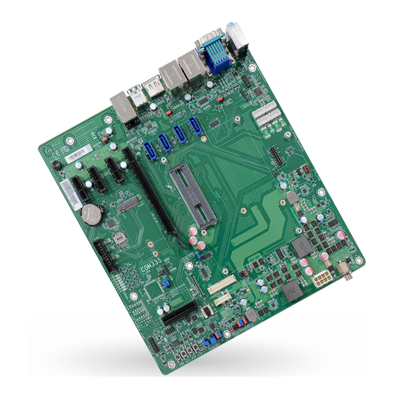
Page 8: Block Diagram
Chapter 1 INTRODUCTION X Block Diagram X Dimension User's Manual | COM335... -
Page 9: Chapter 2 - Hardware Installation
8PIN USB4&5 (2.0) USB6&7 (2.0) COM Express Connector USB0&1 LVDS (3.2 Gen2) Inverter COM Express Connector DPJP11 2.5G LAN DPJP14 LVDS USB2 DPJP13 (3.2 Gen2) DPJP10 JP16 JP15 JP17 M.2 BKey 3045/52 JP18 PEG&PCIE Connector Header User's Manual | COM335... -
Page 10: Jumper Settings
JP15 JP15 JP17 JP17 M.2 BKey M.2 BKey 3045/52 3045/52 JP18 JP18 PEG&PCIE PEG&PCIE Connector Connector Header Header „ 2-3 On: 5V „ 2-3 On: 5V „ 1-2 On: 12V (default) „ 1-2 On: 12V (default) User's Manual | COM335... -
Page 11: Panel Backlight (Dpjp13)
M.2 BKey M.2 BKey 3045/52 3045/52 JP18 JP18 PEG&PCIE PEG&PCIE Connector Connector Header Header „ 2-3 On: 5V „ 1-2 On: 3V3 (default) „ 1-2 On: 12V „ 3-4 On: 5V „ 5-6 On: 3.3V (default) User's Manual | COM335... -
Page 12: Atx/At Mode (Jp16)
JP15 JP15 JP17 M.2 BKey JP17 M.2 BKey 3045/52 JP18 3045/52 JP18 PEG&PCIE PEG&PCIE Connector Connector Header Header „ 2-3 On: AT „ 1-2 On: ATX (default) „ 2-3 On: AT „ 1-2 On: ATX (default) User's Manual | COM335... -
Page 13: Come Type6&Type10 (Jp17)
JP17 M.2 BKey JP17 M.2 BKey 3045/52 JP18 3045/52 JP18 PEG&PCIE PEG&PCIE Connector Connector Header Header „ 2-3 On: COMe TYPE6 „ 1-2 On: COMe TYPE10 „ 2-3 On: Host present „ 1-2 On: Host present User's Manual | COM335... -
Page 14: Lvds &Edp (Jp9)
LVDS (3.2 Gen2) Inverter COM Express Connector DPJP11 2.5G LAN DPJP14 LVDS DPJP13 USB2 (3.2 Gen2) DPJP10 JP16 JP15 JP17 M.2 BKey 3045/52 JP18 PEG&PCIE Connector Header „ 2-3 On: GND „ 1-2 On: 3V3 (default) User's Manual | COM335... -
Page 15: Pin Assignment
LVDS USB2 DPJP13 USB2 DPJP13 (3.2 Gen2) (3.2 Gen2) DPJP10 DPJP10 JP16 JP16 JP15 JP15 JP17 JP17 M.2 BKey M.2 BKey 3045/52 3045/52 JP18 JP18 PEG&PCIE PEG&PCIE Connector Connector Header Header Assignment Assignment CAN-High TACH CAN-Low User's Manual | COM335... -
Page 16: S/Pdif (Auj1)
(3.2 Gen2) DPJP10 (3.2 Gen2) DPJP10 JP16 JP16 JP15 JP15 JP17 M.2 BKey JP17 M.2 BKey 3045/52 JP18 3045/52 JP18 PEG&PCIE PEG&PCIE Connector Connector Header Header Assignment Assignment SER1_TX SER1_TX/CAN_TX SPOUT CAN_TX SER1_RX SER1_RX/CAN SPIN CAN_RX User's Manual | COM335... -
Page 17: Bios Boot Selection (J10)
JP16 JP16 JP15 JP15 JP17 JP17 M.2 BKey M.2 BKey 3045/52 3045/52 JP18 JP18 PEG&PCIE PEG&PCIE Connector Connector Header Header Assignment Assignment MIC2-L A_GND Assignment Assignment 3V3SB 3V3SB MIC2-R BIOS_DIS1- BIOS_DIS0- LINE2-R MIC2-JD A_GND LINE2-L LINE2-JD User's Manual | COM335... -
Page 18: Lpc_Espi_Header (J9)
Connector 3045/52 JP18 PEG&PCIE Header Connector Header Assignment Assignment Assignment Assignment 12V_IO LPC_CLK_ESPI_CK_R LPC_AD1_ESPI_IO1_R GPO3 12V_IO LPC_RST LPC_AD0_ESPI_IO0_R GPO2 LPC_FRAME-_ESPI_CS0-_R 3V3SB/3V3 GPO1 LPC_AD3_ESPI_IO3_R GPO0 LPC_AD2_ESPI_IO2_R GPI3 LPC_SERIRQ_ESPI_CS1-_R GPI2 5VSB 5VSB GPI1 5VSB ESPI_RESET- ESPI_ALERT0- GPI0 ESPI_ALERT1- User's Manual | COM335... -
Page 19: Lvds Connector (Dpcn12)
LVDSB_Y1+ DPJP11 2.5G LAN DPJP14 LVDS USB2 DPJP13 (3.2 Gen2) DPJP10 LVDSA_Y1- LVDSB_Y1- JP16 JP15 JP17 M.2 BKey 3045/52 JP18 LVDSA_Y0+ LVDSB_Y0+ PEG&PCIE Connector Header LVDSA_Y0- LVDSB_Y0- LVDSA_CLK+ LVDSB_CLK+ LVDSA_CLK- LVDSB_CLK- EDID_CLK EDID_DATA LVDS_3V3 PANEL-PWR PANEL-PWR User's Manual | COM335... -
Page 20: Expansion Slots
USB0&1 LVDS (3.2 Gen2) Inverter COM Express Connector DPJP11 2.5G LAN DPJP14 LVDS USB2 DPJP13 (3.2 Gen2) DPJP10 JP16 JP15 JP17 M.2 BKey 3045/52 JP18 M.2 Module M.2 Socket PEG&PCIE Connector Header Stand-off Notch M.2 B-Key User's Manual | COM335... - Page 21 Screw tight the card onto the stand-off with a screw driver and a stand-off screw until the gap between the card and the stand-off closes up. The card should be lying parallel to the board when it’s correctly mounted. User's Manual | COM335...
Need help?
Do you have a question about the COM335 and is the answer not in the manual?
Questions and answers