
Related Manuals for ELTEX WB-2P-LR5


Summary of Contents for ELTEX WB-2P-LR5
- Page 1 User station WB-2P-LR5 User manual Firmware version 2.3.0 IP address: 192.168.1.1 Username: admin Password: password...
-
Page 2: Table Of Contents
WB-2P-LR5. User manual Contents Introduction ..............................4 Annotation ..............................4 Symbols ..............................4 Device description ............................5 Purpose ..............................5 Device specification..........................5 Technical features ............................7 Design ................................9 Light indication............................10 Reset to the default settings ........................11 Delivery package .............................11 Installation order ............................12 Safety rules..............................12 Installation recommendations .......................12... - Page 3 WB-2P-LR5. User manual 5.1.9 The «Conntrack» submenu......................... 26 5.1.10 The «Routes» submenu ........................28 The «Network» menu ..........................29 5.2.1 The «Internet» submenu ........................29 5.2.2 The «Radio» submenu ........................38 5.2.3 The «LAN» submenu........................... 40 5.2.4 The «MAC address Management» submenu ..................41 5.2.5...
-
Page 4: Introduction
WB-2P-LR5 is a user station designed for connection to Wi-Fi access network which might be constructed using base stations within long distances. The case of WB-2P-LR5 is sealed, that is allows to install the device outdoor with different climate conditions. -
Page 5: Device Description
The device provides access to up-to-date interactive services: Internet, IPTV, VoIP. WB-2P-LR5 connects to a base station via Wi-Fi technology and operates at 5 and 6 GHz (the frequency range – 5830-6150 MHz – is supported on WB-2P-LR5 rev.B and WB-2P-LR5 rev.C). The device is supposed to operate with WOP-2ac-LR5. - Page 6 DHCP-based autoprovisioning; • support for TR-069; • remote monitoring, configuration and setup: SNMP, web interface, Telnet, SSH. The figures below illustrate applications schemes of WB-2P-LR5. Functional scheme of using WB-2P-LR5 without router Functional scheme of using WB-2P-LR5 with router...
-
Page 7: Technical Features
WB-2P-LR5. User manual Functional scheme of using WB-2P-LR5 for wireless bridge organization 2.3 Technical features Table 1 shows main specifications of the device. Table 1 — Main specifications LAN Ethernet interface parameters Number of ports Electrical connector RJ-45 Data rate, Mbps... - Page 8 WB-2P-LR5. User manual Beam angle (horizontal polarization) 60° Beam angle (horizontal polarization) 15° 2.0:1 Impedance 50 Ohm Front to back ratio > 20 dB Control Remote control Web interface, Telnet, SSH, SNMP (monitoring), TR-069 Access restriction by password General parameters...
-
Page 9: Design
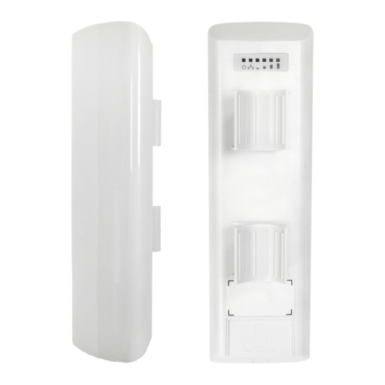
WB-2P-LR5. User manual 2.4 Design WB-2P-LR5 housed in a plastic case, industrial version. The size of the device: 80x66x282 mm. The layout of WB-2P-LR5 is shown in the figure below. WB-2P-LR5 layout LAN port 10/100/1000Base-T (RJ-45 connector) for local network connection and power supply via PoE, a grounding connector (for WB-2P-LR5 rev.C ) -
Page 10: Light Indication
The light indication panel of WB-2P-LR5 is shown below. WB-2P-LR5 light indication panel The current state of the device is shown with the help of light indicators located on the back panel of WB-2P-LR5. The list of indicators and their description is shown in the table below. -
Page 11: Reset To The Default Settings
Using PoE injector supplied with the device. When the device is loaded, press and hold «RST» button of the injector (approximately 10–15 seconds) until «Power» indicator of WB-2P-LR5 is flashing orange. Device will be rebooted automatically. DHCP client will be launched by default. If the address is not received via DHCP the device will have IP address — 192.168.1.1, subnet mask — 255.255.255.0;... -
Page 12: Installation Order
Install the device vertically on communications mast or pole in the way that the LAN port is pointed down. In order to provide better receiving signal level, the sectoral antenna of a base station should be in line of sight of WB-2P-LR5. You may achive the highest signal level by antenna alignment with the help of RSSI indicators. - Page 13 2. Remove the bottom cover which close LAN-port. Ground the device through a grounding connector (for WB-2P-LR-5 rev.C). 3. Connect Ethernet cable to LAN port. 4. Close the bottom cover. 5. Connect Ethernet cable connected to WB-2P-LR5 to PoE port of injector.
- Page 14 WB-2P-LR5. User manual 6. Connect Ethernet cable of your LAN network or PC to LAN port of PoE injector. 7. Connect PoE injector to 220V socket with the help of power line cord. 8. Align the position of the device for best signal level receiving. The level of received signal is shown by the indication located on the back panel of the device.
-
Page 15: Switching On
3.5 Wi-Fi antenna alignment For ease of antenna alignment the Service Wi-Fi is implemented in the device (only for WB-2P-LR5 rev.C). It allows to connect the wireless client to the "EltexWiFi" SSID (2.4 GHz frequency band) and align antennas using data of monitoring of the connection parameters of the subscriber station WB-2P-LR5 with the base station in WEB... -
Page 16: Device Management Via Web Configurator
WB-2P-LR5. User manual 4 Device management via WEB configurator 4.1 Getting started To start, you need to connect the device through a browser: Open a web browser (web-page explorer), for example, Firefox, Opera, Chrome. Enter IP-address of the device to the browser address line. -
Page 17: Changing User
WB-2P-LR5. User manual You may select languages on the top-right of the page. Russian and English languages are available. 4.2 Changing user There are two user types for the device: admin and viewer: • admin(password by default: password) has the full access to the device: read/write any settings, full device status monitoring. -
Page 18: Applying Configuration And Discarding Changes
WB-2P-LR5. User manual 4.3 Applying configuration and discarding changes Applying configuration Press «Apply» to save configuration to flash memory and apply new settings. All the settings come into operation without device rebooting. The visual indication of the settings applying is realized in the web interface. ... -
Page 19: Main Elements Of The Web Interface
WB-2P-LR5. User manual 5 Main elements of the WEB interface The figure below shows navigation elements of the web configurator. The user interface is divided into seven areas: Username, which was used to enter the system and «logout» button to finish the user session. -
Page 20: The «Monitoring» Menu
WB-2P-LR5. User manual 5.1 The «Monitoring» menu To move to the system monitoring mode, select «Monitoring» on the left panel. Some pages are not updated automatically. To obtain current state of the device, press 5.1.1 The «Internet» submenu In the Internet submenu, you may view main network parameters of the device. -
Page 21: The «Wds» Submenu
WB-2P-LR5. User manual minimum value is 0% (no packets were successfully sent). The parameter value is calculated for the last 10 • Link Quality Common – parameter that displays the status of the link, calculated based on the number of sent retransmit packets. -
Page 22: The «Ethernet Ports» Submenu
WB-2P-LR5. User manual minimum value is 0% (no packets were successfully sent). The parameter value is calculated for the last 10 • Link Quality Common – parameter that displays the status of the link, calculated based on the number of sent retransmit packets. -
Page 23: The «Dhcp» Submenu
WB-2P-LR5. User manual 5.1.4 The «DHCP» submenu The list of network devices connected to LAN interface of the device, whose IP addresses were assigned by local DHCP server, is given in the DHCP submenu. The expire time of address lease is shown in the table as well. -
Page 24: The «Pppoe Relay» Submenu
WB-2P-LR5. User manual 5.1.6 The «PPPoE Relay» submenu The «PPPoE Relay» submenu is available only in Wireless station mode • Sessions Count – the quantity of PPPoE sessions established through the device. The maximum value – 64. • Status – active or inactive session. -
Page 25: The «Device Info» Submenu
WB-2P-LR5. User manual 5.1.8 The «Device Info» submenu General information on the device is given in the Device Info submenu. Device info • Product - device model name; • Firmware Version – device firmware version; • Factory MAC Address – MAC address of the device's WAN interface, defined by the manufacturer;... -
Page 26: The «Conntrack» Submenu
WB-2P-LR5. User manual 5.1.9 The «Conntrack» submenu In the «Conntrack» submenu you can find the current active network connections of the device. Active NAT Session • Active Connections – total number of active network connections; • Shown Connections – number of connections shown in the WEB interface. In order to maintain high performance of the WEB interface, the maximum number of connections shown is limited to 1024. - Page 27 WB-2P-LR5. User manual To get current information, click the 'Refresh' button. ...
-
Page 28: The «Routes» Submenu
WB-2P-LR5. User manual 5.1.10 The «Routes» submenu In the Routes submenu you may view the device route table. • Destination – IP address of destination host or subnet that the route is established to; • Gateway – IP address of the gateway, through which access to the addressee is implemented;... -
Page 29: The «Network» Menu
WB-2P-LR5. User manual 5.2 The «Network» menu You may implement main network settings in the «Network» menu. 5.2.1 The «Internet» submenu In «Internet» submenu, you may configure parameters to connect to a base station via Wi-Fi and select connection mode. - Page 30 40/80 MHz bandwidth. When using the WB-2P-LR5 with WOP-2ac-LR5 devices with enabled fixed center frequency, activation at the subscriber station is not required, because happens automatically at the moment of connection to the base station.
- Page 31 WB-2P-LR5. User manual setting, the WB-2P-LR5 will only scan the frequency range of 5,490 - 5,530 MHz and successfully connect to the BS on the 100L/40 channel; • Fixed Transmit Rate – fixed wireless data transmission rate which is defined by IEEE 802.11a/n/ac standards;...
- Page 32 WB-2P-LR5. User manual version] Example: [VENDOR:Eltex][DEVICE:WB-2P-LR5][HW:1.2][SN:WP29000038] [WAN:E0:D9:E3:75:55:60] [LAN:E0:D9:E3:75:55:60][VERSION:2.0.0.161] • PPPoE (available in router mode) – operation mode when PPP session is established on WAN interface. When PPPoE is selected, the following parameters will be available for editing: • Username – user name for authorization on PPP server;...
- Page 33 WB-2P-LR5. User manual • Use General VLAN – when checked, one VLAN specified in the General VLAN ID field will be removed and the traffic of this VLAN will go to the client without a tag. When traffic flows in the opposite direction, untagged traffic will be tagged with General VLAN ID: •...
- Page 34 WB-2P-LR5. User manual If the “Use Management VLAN” flag is checked and the Management VLAN is configured incorrectly, access to the device may be lost. When connected via Ethernet, the device will be available at 192.0.3.1. • Use Internet VLAN – when checked, VLAN is enabled to transmit user traffic.
- Page 35 WB-2P-LR5. User manual If PPPOE is selected as the Internet protocol, then you can specify the secondary access settings: • Secondary access – defines the method of setting the IP address on the interface for accessing the device if the management VLAN is not used.
- Page 36 WB-2P-LR5. User manual Wireless bridge mode • Hostname – a name of the network device; • Device mode – a mode of device connection; • Priority – select prioritization means. Defines a field based on which traffic transmitted to the radio interface will be distributed among WMM queues: •...
- Page 37 WB-2P-LR5. User manual address field. • Alternative VendorID (Option 60) – when selected, the device transmits VendorID (Option 60) in Option 60 DHCP messages (Vendor class ID). If the field is empty, Option 60 will not be transmitted in DHCP messages.
-
Page 38: The «Radio» Submenu
WB-2P-LR5. User manual 5.2.2 The «Radio» submenu «Radio» submenu is available only in «Wireless bridge» mode. In the 'Radio' submenu, you may configure the radiointerface to organize wireless bridge. Basic settings: • Scan Environment – press the button to start scanning at the defined range. The list of found access points will be displayed. - Page 39 WB-2P-LR5. User manual Advanced settings: • Fragmentation Threshold – frame fragmentation threshold, bytes. The parameter takes values 256-2346, by default – 2346. • RTS Threshold – after what quantity of bytes the Request to Send will be sent. Decreasing of the parameter's value might improve access point operation when there are a lot of clients connected. However, decreasing of the parameter's value will reduce general bandwidth of wireless network.
-
Page 40: The «Lan» Submenu
WB-2P-LR5. User manual 5.2.3 The «LAN» submenu LAN settings are available only in router mode. In LAN settings section you may configure local network, DHCP server, set static addresses bindings. The device is capable to assign IP addresses and other parameters required to the Internet access to computers connected to LAN interface through DHCP (Dynamic Host Configuration Protocol). -
Page 41: The «Mac Address Management» Submenu
WB-2P-LR5. User manual DHCP server settings: • Enable – when cheked, a local DHCP server is enabled, otherwise the server is disabled; • Start IP address – the initiate address of the IP addresses pool; • Pool size – the number of addresses in the pool;... -
Page 42: The «Local Dns» Submenu
«Wireless transparent bridge» settings are available for Bridge mode of Wi-Fi station only. When you enable Wireless transparent bridge, WB-2P-LR5 will not substitute client MAC addresses from LAN with own MAC address. The limit is 15 MAC addresses without substitution. When the value is exceeded client's MAC address will be substituted. -
Page 43: The «Nat And Port Forwarding» Submenu
WB-2P-LR5. User manual Click Apply to create 'IP address – domain name' pair. To discard changes click the Cancel button. To delete the record from the list, select the checkbox next to the respective record and click 'Delete'. 5.2.6 The «NAT and Port Forwarding» submenu ... - Page 44 WB-2P-LR5. User manual NAT rules To add a new NAT rule, click Add button and fill in the following fields in the Add a new rule window: • Name – name of the rule (it is obligitory to fill the field);...
-
Page 45: The «Firewall» Submenu
WB-2P-LR5. User manual 5.2.7 The «Firewall» submenu In the Firewall submenu, you may set the rules for the incoming, outgoing, and transit traffic transmission. There is an opportunity to limit transmission of different types of traffic (incoming, outgoing, transit) depending on protocol type, source and destination IP, TCP/UDP source and destination ports, type of ICMP message. - Page 46 WB-2P-LR5. User manual or 192.168.16.0/255.255.255.0 to set addresses range (the subnet mask entry /24 coincides with /255.255.255.0 entry); • Output – outgoing traffic (traffic which is generated by the device locally from a network interface). If the parameter is selected, the following field will be displayed: •...
-
Page 47: The «Routes» Submenu
WB-2P-LR5. User manual 5.2.8 The «Routes» submenu You may set static routes in the Routes submenu. Press «Add» button to add a new route. Fill the following fields: • Name – route name. • Destination – destination host or subnet IP address, to which the route will be set. -
Page 48: The «Dynamic Dns» Submenu
WB-2P-LR5. User manual 5.2.9 The «Dynamic DNS» submenu Dynamic DNS submenu is available only in router mode. In dynamic DNS submenu, you may configure the coresponding service. • Dynamic DNS (D-DNS) provides information on DNS server update in real time or automatically, if necessary. -
Page 49: The «Snmp» Submenu
WB-2P-LR5. User manual 5.2.10 The «SNMP» submenu WB-2P-LR5 software allows monitoring of the device status and its sensors via SNMP. In SNMP submenu, you can configure settings of SNMP agent. The device supports SNMPv1, SNMPv2c. • Enable SNMP – when checked, SNMP will be enabled for utilization;... -
Page 50: The «Iptv» Menu
WB-2P-LR5. User manual 5.3 The «IPTV» menu The menu is available only in router mode. 5.3.1 The «IPTV» submenu You may configure IPTV service in IPTV settings menu. • Enable IPTV – when checked, IPTV signals transmission via WAN interface (from provider network) to the devices connected to the LAN interface is enabled;... - Page 51 WB-2P-LR5. User manual HTTP Proxy Settings • Enable – when checked, HTTP Proxy function is enabled. HTTP Proxy implements modification of UDP stream to HTTP stream using TCP (transmission control protocol), that allows to improve quality of transmitted image in case of poor communication channel quality in a local network. The function is useful when IPTV is watched via wireless Wi-Fi channel.
-
Page 52: The «System» Menu
WB-2P-LR5. User manual 5.4 The «System» menu In the System menu, you may configure system parameters: time, access via different protocols, change password, update software. 5.4.1 The «Time» submenu The configuration of time synchronization protocol (NTP) is implemented in the Time submenu. -
Page 53: The «Access» Submenu
WB-2P-LR5. User manual 5.4.2 The «Access» submenu In the Access submenu, you may configure access to the device via web interface, Telnet and SSH. Access ports In this section you may configure TCP ports for the access to the device via HTTP, HTTPS, Telnet, and SSH. -
Page 54: The «Log» Submenu
WB-2P-LR5. User manual SSH: SSH – is a secure device remote control protocol. As opposed to Telnet, SSH encrypts all traffic being transferred including passwords. To enable the device access via SSH protocol, select the corresponding checkbox. To apply a new configuration and store settings into the non-volatile memory, click the 'Apply' button. To discard changes click the Cancel button. - Page 55 WB-2P-LR5. User manual Select types of messages to be output in Networkd Log: • Error – check to collect «Error» type messages; • Warnings – check to collect «Warning» type messages; • Debug – check to collect debug messages; • Info – check to collect information messages;...
-
Page 56: The «Passwords» Submenu
WB-2P-LR5. User manual 5.4.4 The «Passwords» submenu In the 'Passwords' submenu you may define passwords for administrator and viewer access. The set passwords are used for access to the device via web interface, Telnet and SSH. When logging in via WEB interface administrator (default password: password) has the full access to the device: read/write any settings, full device status monitoring. -
Page 57: The «Configuration Management» Submenu
WB-2P-LR5. User manual 5.4.5 The «Configuration management» submenu In the «Configuration management» submenu you may save and update the current configuration. Backup configuration To save the current device configuration to a local PC, click «Download» button. Restore Configuration •... -
Page 58: The «Firmware Upgrade» Submenu
WB-2P-LR5. User manual 5.4.6 The «Firmware Upgrade» submenu The Firmware Upgrade submenu is dedicated to update firmware version of the device. WB-2P-LR5 firmware upgrade: • Active Version of Firmware – installed firmware version, which is operating at the moment; •... -
Page 59: The «Reboot» Submenu
WB-2P-LR5. User manual 5.4.7 The «Reboot» submenu In the «Reboot» submenu you may reboot the device. Click the «Reboot» button to reboot the device. Device reboot process takes approximately 1 minute to complete. 5.4.8 The «Autoprovisioning» submenu In the «Autoprovisioning» submenu you may configure DHCP-based autoprovisioning algorithm and subscriber... - Page 60 WB-2P-LR5. User manual DHCP-based Autoprovisioning: • Provisioning Mode – select a mode for automatic device update. The followings are available: • Disabled – automatic update of configuration and firmware is disabled; • Configuration and Firmware – periodical configuration and firmware update is permitted;...
-
Page 61: The «Advanced» Submenu
WB-2P-LR5. User manual NAT Settings: If there is modification of network addresses between client and ACS server (NAT – network address translation), ACS server might not have the opportunity to establish connection with the client if certain technologies are not used to avoid it. - Page 62 Service Wi-Fi • Service Wi-Fi (available only for WB-2P-LR5 rev. C) is used when aligning Wi-Fi (section 3.5 Wi-Fi antenna alignment). With Service Wi-Fi enabled, a Wi-Fi client can connect to the device via an open network with the "EltexWiFi" SSID (2.4 GHz frequency band).
-
Page 63: Configuration Example
WB-2P-LR5. User manual 6 Configuration Example Connect PC to LAN port of injector; Enter IP address of the device to URL bar of a browser (192.168.1.1 by default, if address was not obtain via DHCP). When connection is established successfully, the window with Login and password fields will be displayed. - Page 64 WB-2P-LR5. User manual Implement configuration on Internet tile. In Network Mode field, select the required mode: Bridge or Router. If static settings are used for connection to a provider network, choose «Static» value in «Protocol» field and fill the fields: «IP address», «Netmask», «Default gateway», «Primary DNS Server», «Secondary DNS Server»...
-
Page 65: Spectrum Analyzer
WB-2P-LR5. User manual 7 Spectrum Analyzer To use the embedded spectrum analyzer on the WB-2P-LR5, you need to login to the device via telnet or ssh. Enter the spectrum-analyzer command to run it. The analysis time for all the radio channels in the range is approximately 5 minutes. -
Page 66: Device Automatic Dhcp-Based Update Algorithm
$SN – Serial number – the macro is substituted with device's serial number in file URL; • $PN – Product name – the macro is substituted with device's model name in file URL (e.g., WB-2P-LR5). For MAC address, serial number and model name, see «Device» section on the monitoring page. - Page 67 • For a server address: update.local; • For a configuration file name wb-2p-lr5.cfg; • For a firmware file name wb-2p-lr5.fw. Thus, if the 'Configuration File' and 'Firmware File' fields are left empty, options 43 or 66, 67 with the location of these files will not be received via DHCP —...
- Page 68 WB-2P-LR5. User manual Option 43 analysis When Option 43 has been received, suboption 8 is analyzed (vlan_tag): • if there is a suboption and it is different from current VLAN tag, DHCP exchange is initiated in new VLAN; • suboption is absent or present and does not differ from the current VLAN tag: suboptions with codes 5, 6, and 7 are analyzed to determine the server address and the names of the configuration files and software.
-
Page 69: System Recovering After Firmware Update Failure
WB-2P-LR5. User manual 9 System recovering after firmware update failure If while the firmware update (through the web interface or through autoupdate mechanism based on DHCP) a failure occured (e.g. due to power cutoff) and the device does not operate (the «Power» indicator is constantly solid red), use the following algorithm to recover the device: •... -
Page 70: Appendix A. Launch User Script When Starting The System
WB-2P-LR5. User manual 10 Appendix A. Launch user script when starting the system Sometimes you need the device to implement certain actions when starting, which cannot be implemented through settings in configuration file. In this case you may configure a user script through a configuration file that will be launched when the system starting. -
Page 71: Appendix B. Antenna Patterns
WB-2P-LR5. User manual 11 Appendix B. Antenna Patterns The pattern of vertically polarized antenna in H-plane: The pattern of vertically polarized antenna in E-plane: The pattern of horizontally polarized antenna in H-plane:... - Page 72 WB-2P-LR5. User manual The pattern of horizontally polarized antenna in E-plane: ...
- Page 73 WB-2P-LR5. User manual The list of changes Document version Issue date Revisions Version 4.0 06.11.2019 Synchronization with firmware version 2.3.0 Changes in sections: • Technical features • Design • Mounting order • Antenna alignment • The Network/Internet menu •...
-
Page 74: Technical Support
+7(383) 274-47-87 +7(383) 272-83-31 E-mail: techsupp@eltex-co.ru You are welcome to visit Eltex official website to get the relevant technical documentation and software, to use our knowledge base or consult a Service Centre Specialist in our technical forum. http://www.eltex-co.ru/en/ http://www.eltex-co.ru/en/support/downloads/...
Need help?
Do you have a question about the WB-2P-LR5 and is the answer not in the manual?
Questions and answers