Table of Contents
Advertisement
Quick Links
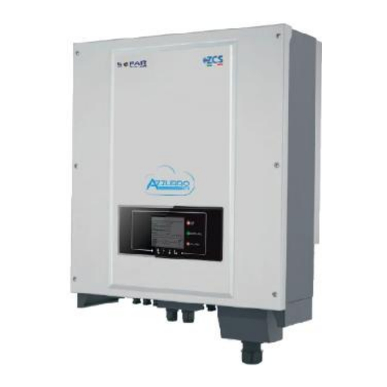
Grid-connected inverter
20K – 33K TL
User Manual
V1.1 (07-06-2019)
Zucchetti Centro Sistemi S.p.A. - Green Innovation Division
Via Lungarno, 248 - 52028 Terranuova Bracciolini - Arezzo, Italy
tel. +39 055 91971 - fax. +39 055 9197515
innovation@zcscompany.com - zcs@pec.it – www.zcsazzurro.com
Reg. Pile IT12110P00002965 - Capitale Sociale € 100.000,00 I.V.
Reg. Impr. AR n.03225010481 - REA AR - 94189
Azienda Certificata ISO 9001 - Certificato n. 9151 - CNS0 - IT-17778
Advertisement
Table of Contents

Related Manuals for ZCS TL Series


Summary of Contents for ZCS TL Series
- Page 1 Via Lungarno, 248 - 52028 Terranuova Bracciolini - Arezzo, Italy tel. +39 055 91971 - fax. +39 055 9197515 innovation@zcscompany.com - zcs@pec.it – www.zcsazzurro.com Reg. Pile IT12110P00002965 - Capitale Sociale € 100.000,00 I.V. Reg. Impr. AR n.03225010481 - REA AR - 94189...
-
Page 2: Table Of Contents
Table of Contents 1. Preliminary safety instructions………………………………………...…….…………………………………………………………….6 1.1. Safety instructions…..………………………………………………………..………..…………………………………………………..6 1.2. Symbols and icons……………………………………………………………….…………………………………………………………9 2. Product features……………….……………………………………………………….………….……………………………………………10 2.1. Product presentation……….…………………………………………………...……………….……………………………………..10 2.2. Description of functions……………………………………………………………………………………….……………………..15 2.3. Protection of modules………………………………………………………………..…………………………………………………18 2.4. Efficiency curve and derating.……………………………………………………………………………………………………….18 3. Installation..………………………………………………………………………………………………………………………………………19 3.1. Installation process………………………………………………………………………...……………………………………………20 3.2. Checks before installation………………………………………………………………….…………………………………………20 3.3. - Page 3 7.1. Troubleshooting…………………………………………………………………………………….…………………………………….65 7.2. Maintenance..…………………………………………………………………………………………...………………………………….72 8. Uninstalling…………………………………………………………………………………….……………...………………………………….73 8.1. Steps for uninstalling the inverter…………………………………………………………………………………………………73 8.2. Packaging…………………………………………………………………………………………………………………………………….73 8.3. Storage…..………………………………………………………………………………………………………………….………………...73 8.4. Disposal…….………………………………………………………………………..…………………………………….…………………73 9. Technical specifications.……………………………………………………………………………………………………………………..74 10. Warranty……………..………………………………………………………………………………………………………………..……………76 3 / 74 Manual of 07/06/2019 Rev. 1.1 “User Manual for 20K-33KTL” Identificazione: MD-AL-GI-00 Rev. 4.0 del 31.01.18 - Applicazione: GID...
-
Page 4: General Instructions
(including the software), reproduced or distributed in any form or by any means without the permission of Zucchetti Centro Sistemi S.p.A. All rights reserved. ZCS reserves the right to final interpretation. This manual is subject to change based on feedback from users, installers or customers. -
Page 5: General Information
Preface General information Please read this manual carefully before installation, operation or maintenance. This manual contains important safety instructions that must be followed during installation and maintenance of the system. Scope This manual describes the assembly, installation, electrical connections, commissioning, maintenance and troubleshooting of the following inverters: 20000TL / 25000TL / 30000TL / 33000TL Keep this manual so that it is accessible at all times. -
Page 6: Preliminary Safety Instructions
1. Preliminary safety instructions If you have problems or questions regarding the reading and understanding of the following information, please contact Zucchetti Centro Sistemi S.p.A. through the appropriate channels. Note General information in this chapter Safety instructions It mainly highlights the safety instructions to be followed during installation and use of the equipment. Symbols and icons Introduces the main safety symbols on the inverter. - Page 7 Attention Do not remove the information label or open the inverter. Otherwise, ZCS will not provide any warranty or maintenance. Note 7 / 74 Manual of 07/06/2019 Rev. 1.1 “User Manual for 20K-33KTL”...
-
Page 8: Maintenance And Repair
Operation Contact with the electrical grid or the terminal of the equipment may cause electrocution or fire! Do not touch the terminal or the conductor connected to the • electrical grid. Follow all the instructions and safety requirements relating to the •... -
Page 9: Symbols And Icons
1.2. Symbols and icons Safety signals Pay attention to possible burns due to hot parts. Only touch the screen or press the keys while the inverter is in operation. Caution The PV strings should be connected to the ground in accordance with the local regulations! To ensure the safety of the system and people, the inverter and •... -
Page 10: Product Features
Read this manual before installing the inverter. Indication of the allowable temperature range Degree of protection of the equipment according to the IEC 70-1 standard (EN 60529 June 1997). Positive pole and negative pole of the input voltage (DC). 2. Product features General information in this chapter Product description and dimensions The field of use and overall dimensions of the 20K-33K TL inverters are indicated in this section. - Page 11 The 20K-33K TL inverters can only be used with photovoltaic modules that do not require one of the poles to be grounded. The operating current and voltage during normal operation must not exceed the limits indicated in the technical specifications. Only photovoltaic modules can be connected to the input of the inverter (do not connect batteries or other power supply sources).
- Page 12 Inverter components Inverter models of the 20K-33K TL family are divided into four sizes according to their maximum output power (20 kW, 25 kW, 30 kW, 33 kW). Figure 4 – Bottom view of the inverter 1. Anti-condensation valve 2.
- Page 13 Figure 5 – Front, side and back view of the inverter and bracket Labels on the inverter Figure 6 – Do not remove the label on the side of the inverter 13 / 74 Manual of 07/06/2019 Rev. 1.1 “User Manual for 20K-33KTL” Identificazione: MD-AL-GI-00 Rev.
-
Page 14: Description Of Functions
2.2. Description of functions The DC voltage generated by the PV modules is filtered through the input board before entering the power board. The input board also has the function of measuring the insulation impedance and the DC input voltage/current. The power board converts the DC power into AC power. The current converted into AC is filtered through the output board and is then fed into the grid. - Page 15 Figure 7 – Block diagram of the 20K-33KTL inverters 15 / 74 Manual of 07/06/2019 Rev. 1.1 “User Manual for 20K-33KTL” Identificazione: MD-AL-GI-00 Rev. 4.0 del 31.01.18 - Applicazione: GID...
- Page 16 Inverter functions A. Configurable relay The inverter has a configurable switching relay that can be used in various operating conditions (set in the menu). For example, it can close normally open contacts when an alarm occurs. B. Energy management unit B.1 Remote power on/off This control can be used to activate/deactivate the inverter via an external (remote) control.
- Page 17 LED on the front panel. 2.4. Efficiency and derating curves Efficiency curve for an Azzurro ZCS 20K-33K TL model Figure 8 – Efficiency curve for an Azzurro ZCS 20K-33 KTL inverter 17 / 74 Manual of 07/06/2019 Rev. 1.1 “User Manual for 20K-33KTL”...
- Page 18 Input voltage derating curve for an Azzurro ZCS 20K-33K TL inverter Figure 9 – Input voltage derating curve for an Azzurro ZCS 20K-33 KTL inverter Output voltage derating curve for an Azzurro ZCS 20K-33K TL inverter Figure 10 – Output voltage derating curve for an Azzurro ZCS 20K-33 TL inverter 18 / 74 Manual of 07/06/2019 Rev.
-
Page 19: Installation
3. Installation General information in this chapter This chapter describes how to install the 20K-33K TL inverter. Installation notes: DO NOT install 20K-33K TL inverters near flammable materials. DO NOT install 20K-33K TL inverters in an area where flammable or explosive materials are stored. -
Page 20: Installation Process
3.1. Installation process Figure 11 – Installation steps 3.2. Checks before installation Checking the outer packaging The packaging materials and components may be damaged during transportation. Therefore, please check the materials of the outer packaging before installing the inverter. Check the surface of the box for external damage such as holes or tears. -
Page 21: Installation Tools
1 certificate 1 user manual 1 warranty 3.3. Installation tools The following tools are required for installation of the inverter and electrical connections; therefore, they must be prepared before installation. Tool Function To drill holes in the wall for Drill fixing the bracket Recommended drill bit: 8 mm To screw and unscrew screws for... - Page 22 To insert the expansion plugs Rubber hammer into the wall holes To remove the DC connectors MC4 removal tool from the inverter Diagonal pliers To cut and tighten the cable ends To remove the outer sheath of Cable stripping tool the cables RJ45 2 pieces...
-
Page 23: Installation Position
ESD gloves Protective clothing Safety goggles Protective clothing Protection mask Protective clothing 3.4. Installation position Choose an appropriate installation location for the inverter. Follow the requirements below to determine the installation position. 23 / 74 Manual of 07/06/2019 Rev. 1.1 “User Manual for 20K-33KTL” Identificazione: MD-AL-GI-00 Rev. - Page 24 Figure 13 – Requirements for installing multiple inverters Note: For safety reasons, ZCS Spa and/or its partners may not carry out any technical repairs or maintenance work, or move the inverter from and to the ground if it is installed at a height of more than 180 cm from the ground.
-
Page 25: Moving The 20K-33K Tl Inverter
3.5. Moving the 20K-33K TL inverter This section describes how to move the inverter correctly 1) When opening the packaging, insert your hands into the slots on both sides of the inverter and take a hold of it as shown in figures 14 and 15. Two people are needed to carry out this operation in order to ensure the safety of people and the correct handling of the inverter. -
Page 26: Installing The 20K-33K Tl Inverter
3.6. Installing the 20K-33 KTL inverter 1) Correctly position the mounting bracket on the wall using a level to ensure that it is straight; mark the six holes using a suitable marker pen. Keeping the hammer drill perpendicular to the wall and avoiding any sudden movements when drilling, drill the six holes at the points marked on the wall using a 8 mm drill bit. -
Page 27: Electrical Connections
4. Electrical connections General information in this chapter This chapter describes the electrical connections of the 20K-33K TL inverter. Carefully read this section before connecting the cables. Before making any electrical connections, ensure that the DC and AC circuit breakers are open. NOTE: Remember that the accumulated electrical charge remains in the inverter capacitor after the DC and AC circuit breakers have been switched off. - Page 28 4.1. Electrical connections Figure 17 – Steps for connecting the cables 4.2. Connecting PNGD cables (grounding) Connect the 20K-33K TL inverter to the ground electrode using ground protection cables (PGND). The inverter does not have a transformer, therefore the positive pole and negative pole of the photovoltaic string does NOT need to be grounded.
- Page 29 Prerequisites: Prepare the PGND cables to be connected (AWG 8 outdoor power cables with a cross-section of 8 mm recommended for grounding purposes);for better identification, use yellow-green cables. Procedure: 1) Remove an adequate length of the external insulation layers using a wire stripper, as shown in figure 18. Note: L2 is approximately 2-3 mm longer than L1 Figure 19 –...
-
Page 30: Connecting The Dc Input Power Cables
4.3. Connecting the DC input power cables Connect the 20-33K TL inverter to the photovoltaic strings using DC input power cables. Select the input mode: the 20-33K TL inverter has two MPPTs, which can function either independently or in parallel, depending on how the system was designed. The user can choose the appropriate MPPT operating mode. - Page 31 Check the polarity of the PV string to ensure the correct connection of the cables to the string. Be sure not to connect the positive or negative pole of the PV string to the ground. Note Make sure that the following information is observed. Otherwise, there is a risk of fire.
- Page 32 Figure 22 – Positive (1) and Negative (2) MC4 connectors Note The positive and negative metal terminals are packed together with the positive and negative connectors respectively. Separate the positive and negative metal terminals after unpacking the inverter so as to avoid confusing the polarities.
- Page 33 L2 is approximately 2 or 3 mm longer than L1. Note: 3) Insert the positive and negative power cables in the corresponding cable glands. 4) Insert the stripped positive and negative power cables into the positive and negative metal terminals respectively, and crimp them using a suitable tool.
-
Page 34: Connecting The Ac Output Power Cables
Figure 26 – Removing the DC connector 4.4. Connecting the AC output power cables Connect the inverter to the AC power distribution network or power grid using AC power cables. Do not use the same AC circuit breaker for multiple inverters. ... - Page 35 Multi-core copper cables The cross-section of the power line must be sized in order to prevent unwanted disconnections of the inverter from the grid due to high impedance of the cable connecting the inverter to the point of supply. In addition, the AC cable must be correctly sized to ensure that the loss of power on the cable is less than 1% of the rated power and to ensure proper functioning of the anti-islanding protection.
-
Page 36: Connecting The Communication Cables
3) Connect the AC power cable according to the following criteria and as shown in the figure: Connect the yellow-green (ground) cable to the terminal labelled “PE”, tighten the wire using a screwdriver; Connect the phase R cable to the terminal labelled “R”, tighten the wire using a screwdriver; Connect the phase S cable to the terminal labelled “S”, tighten the wire using a screwdriver;... - Page 37 Connecting the RS485 communication cables When using the RS485 communication line, the inverter must be connected to the communication equipment (for example, to a data acquisition device or PC terminal). For communication via the RS485 line, it is recommended to use AWG 24 shielded outdoor network cables with an internal resistance of less than or equal to 1.5 ohm/10m and external diameter between 4.5 mm and 7.5 mm.
- Page 38 Figure 33 – Assembling the communication connector Crimp the plug using the RJ45 crimping tool. Insert the plug into the RS485 port on the inverter. Insert the cable seal in the lodging and tighten the nut. Figure 34 – Assembling the communication connector Removal procedure Remove the RJ45 connector from the inverter by removing the plug.
- Page 39 2) Connect the external Wi-Fi module. 3) Fix the external Wi-Fi module using the two screws supplied. Note: follow the appropriate procedure to configure the external Wi-Fi adapter. Description of the communication ports This section describes the functions of the RS485 and Wi-Fi ports. 39 / 74 Manual of 07/06/2019 Rev.
- Page 40 RS485 The RS485 port allows transferring information regarding the power produced, the alarms and the operating status of the inverter to the local data acquisition device, and to then upload this information to a server. Figure 35 – Communication systems: USB-RS485 converter and data logger terminal Note: in the case of a single inverter connected via RS485 or in the case of the last inverter in a daisy-chain of multiple inverters connected via RS485, configure the insulation resistance using the SWT2 switches, following the indications shown in the table below (O OFF, 1 ON) and in the figure below.
- Page 41 If the system consists of multiple inverters, connect each of them in a daisy chain using a RS485 communication cable. Then set the RS485 address according to what is reported in section 6.3 (refer to the figure below). Note: It should be remembered that it is always necessary to provide technical support with the serial number of the inverter and the Wi-Fi adapter to allow remote monitoring via the application or website.
- Page 42 Note: it is necessary to provide Zucchetti Centro Sistemi S.p.a. with the serial number in order to activate www.zcsazzurrowebportal.com. the inverter’s remote monitoring system. This can be sent to Figure 36 – Connecting an inverter with Wi-Fi Notes: Note 1: The RS485 communication cable must not be longer than 1000 m. Note 2: The network cable for communicating with the Wi-Fi router must not be longer than 1000 m.
- Page 43 Connecting the relay cable Procedure 1) Prepare the appropriate cable. Remove the insulating sheath, as shown in the figure below; then pass the cable through the waterproof nut. 2) Insert the sealing cap and tighten the nut. 3) Connect the stripped cable into the appropriate terminal of the terminal block. 43 / 74 Manual of 07/06/2019 Rev.
-
Page 44: Commissioning The Inverter
5. Commissioning the inverter 5.1. Safety inspection before commissioning Make sure that the DC and AC voltages are within the range permitted by the inverter. Attention Photovoltaic strings Before turning on the inverter, the photovoltaic string must be examined. Check the open-circuit voltage of each photovoltaic panel and compare it with the data in the technical datasheet. -
Page 45: Operating Interface
If the inverter indicates the presence of any faults, refer to chapter 7.1 of this manual or contact the Zucchetti Centro Sistemi S.p.A. technical support. Operating interface General information in this chapter This section describes the display and its operation, as well as the buttons and LED indicators of the 20-33K TL inverters. -
Page 46: Main Interface
o Steady: GFCI fault indication (ID12: automatic differential circuit breaker fault or ID20: device fault). o Off: GFCI in operation (automatic differential circuit breaker) normal 6.2. Main interface The main LCD interface is used to display the statuses of the inverter, information, configuration of parameters, etc. -
Page 47: Main Menu
A17 – Energy produced from 3:00am to 9:00pm today When the power is turned on, ZCS INNOVATION…. appears on the screen, as shown in the figure below when the control board is correctly connected to the communication board, the LCD screen will display the current status of the inverter, as shown in the figure below. -
Page 48: Main Menu
follows: Press the “OK” key to enter the “Settings” menu. The “Settings” menu contains the following sub-menu: Date and time Select “1. Date and time” and press “OK” to enter the menu for setting the date/time. First set the date and then the time using the “Up”... - Page 49 Select “2. Clear Energy” and press “OK” to enter the menu for deleting the energy data and in particular the energy produced daily and in total, which is shown in the main interface. Press “OK” to start the procedure; the display will show “Enter PWD!”, press “OK” to enter the password. Enter the password “0001” using the “Up”...
- Page 50 Contr On-Off Select “5. Contr On-Off” and press “OK” to enter the menu for setting the remote control switch. The display will show “Enter PWD!.” Press “OK” to enter the password “0001” using the “Up” and “Down” keys to select the number and “OK”...
- Page 51 standby condition until the alarm or warning disappears. Disabling the relay The control function is not permitted. Enable country Select 7 “Enable country” and press “OK” to enter the menu for enabling the selection of the country code. The display will show “Enter PWD!”, press “OK” to enter the password. Enter the password “0001” using the “Up”...
- Page 52 A faster way to change the language is to press the “Menu/Back” key and the “OK” key at the same time. In the current firmware version (V1.60), the available languages are Chinese, English, Italian, German, French, Ukrainian, Slovak and Portuguese; future firmware updates may add additional languages. ...
- Page 53 Insulation The user can change the value of the insulation resistance directly from the LCD display. The user must first copy the TXT files to the SD card. These files can be requested from Zucchetti Centro Sistemi Spa technical support.
- Page 54 again,” press the “Back” key and enter the password again. When the password has been entered correctly, you can enter the menu. Now you can use the “Up” and “Down” keys to select the “1.Enable” or “2.Disable” option and select it with the “OK” key. If the option “1.Enable” is selected, the function for checking the ground line will be executed and the inverter will not start producing power if the grounding line is not present and properly connected;...
- Page 55 Q(v) Setting Select “23. Set Q(v)” and press “OK” to enter the relative menu, from which you can change the reactive power according to the grid voltage required by the local regulations. This function may be required by various regulations for grid-connected inverters. Use the “Up”, “Down” and “OK” keys to set the time delay expressed in seconds (*.***s) before the changed Q reactive power will intervene.
- Page 56 56 / 74 Manual of 07/06/2019 Rev. 1.1 “User Manual for 20K-33KTL” Identificazione: MD-AL-GI-00 Rev. 4.0 del 31.01.18 - Applicazione: GID...
- Page 57 Standard Self-test 1) During normal operation of the inverter, press the “Back” key to enter the main menu. 2) Press the “OK” key to enter the “Settings” menu. 3) Press the “Down” key several times until “26. Standard Self-Test” is shown on the screen. 4) Press “OK”...
- Page 58 58 / 74 Manual of 07/06/2019 Rev. 1.1 “User Manual for 20K-33KTL” Identificazione: MD-AL-GI-00 Rev. 4.0 del 31.01.18 - Applicazione: GID...
- Page 59 Press the “OK” key to enter the “Event List” menu. The “Event List” menu is used to display the events recorded by the inverter, both historical and in real time, showing the progressive number of the event, its identification code, and the date and time of its occurrence.
-
Page 60: Inverter Type
Inverter type Use the “Up” and “Down” keys in the “System Info” menu to move, and the “OK” key to enter the “1. Inverter type” menu. Here you can see the power of the inverter model Serial number Use the “Up”... - Page 61 MicroSD to SD adapter or MicroSD to USB adapter for inserting the MicroSD card into the PC. Firmware update procedure 1. Switch off the ZCS inverter by first disconnecting the AC power supply via the switch installed on the system, and then disconnecting the DC power supply via the switch located on the side of the 61 / 74 Manual of 07/06/2019 Rev.
- Page 62 inverter (if equipped) or switch off the system’s disconnecting switch. Wait for the display to turn off completely. 2. Unscrew the four star screws and remove the central cover found on the bottom on the inverter, taking care to have first loosened the four cable glands. 3.
-
Page 63: Troubleshooting And Maintenance
7. Troubleshooting and maintenance 7.1. Troubleshooting This section contains information and procedures on how to troubleshoot any faults and errors that may occur during operation of the 20K-33K TL inverter. If you have any problems with the inverter, please follow these steps. ... - Page 64 local grid operator. Check whether too few photovoltaic modules have been connected in series in a PV string: therefore, the voltage (Vmp) of the PV string is lower than the minimum operating The input voltage is PVUVP voltage of the inverter. In this case, ID05 too low.
- Page 65 If the error occurs occasionally, the probable cause is that the grid has temporary faults. If the fault occurs frequently, check GridFault Grid fault whether the mains voltage and ID13 frequency are in an acceptable range. If not, contact technical support. Otherwise, check the conditions of the AC switch and the cable harness.
- Page 66 ID26-ID27 are internal faults of the The bus voltage is too inverter; turn off the “DC switch”, wait BusOVP ID26 high. 5 minutes and then turn it back on again. Check that the fault is no longer present. If this is not the case, contact The bus voltage is not VbusUnbalance Technical Support.
- Page 67 master DSP and the slave DSP is not suitable. The sampling value of the automatic differential circuit ConsistentFault_GFCI breaker between the ID52 master DSP and the slave DSP is not suitable. SPI communication between the master SpiCommLose ID53 DSP and the slave DSP is faulty.
- Page 68 present. If this is not the case, contact The bus voltage is too Technical Support. UnrecoverBusOVP high and has caused ID66 an irreparable fault. The grid current is not balanced and has UnrecoverIacRmsUnbalance ID67 caused an irreparable fault. The input current is not balanced and has UnrecoverIpvUnbalance ID68...
- Page 69 Check that the installation position and the installation method meet the The inverter has requirements of Section 3.4 of this been derated user manual. OverTempDerating because the ID81 Check if the ambient temperature in temperature is too the installation location exceeds the high.
-
Page 70: Maintenance
The software between The software version is the control board and Contact Technical Support to update ID94 unsuitable communication board the software. is unsuitable. The EEPROM of the Faulty EEPROM ID95-ID96 are internal faults of the communication board ID95 communication board. inverter;... -
Page 71: Uninstalling
8. Uninstalling 8.1. Steps for uninstalling the inverter Disconnect the inverter from the AC grid by opening the AC circuit breaker. Disconnect the inverter from the photovoltaic strings by opening the DC circuit breaker. Wait 5 minutes ... -
Page 72: Technical Specifications
9. Technical specifications Technical specifications 20 KTL 25 KTL 30 KTL 33 KTL Input (DC) Typical power of PV system 26000W 32500W 39000W 42900W Maximum DC power for each 13000W 16000W 18000W 20000W MPPT Number of independent MPPTs Number of DC inputs 2 for each MPPT 3 for each MPPT Maximum DC input voltage... - Page 73 Standard EN 61000-6-1/2/3/4 Safety standard IEC 62116, IEC 61727, IEC 61683, IEC 60068-1/2/14/30, IEC 62109-1/2 CE, CGC, AS 4777, AS 3100, VDE-AR-N 4105, EN50438, G83/2, G59/3, Grid connection standard C10/11, CEI 0-21 Communication Communication interface Wi-Fi (optional), RS485 (proprietary protocol), microSD card Additional inputs I/O inputs for connection to anti-reverse power controller Data storage...
-
Page 74: Warranty
10. Warranty Zucchetti Centro Sistemi SpA provides a warranty of 10 years from the date of installation on the 20K-33K TL inverter, subject to registration on the website https://www.zcsazzurro.com/it/estensione-garanzia. any case, the warranty cannot exceed 126 months from the date of delivery of the inverter. During the warranty period, Zucchetti Centro Sistemi S.p.A.
Need help?
Do you have a question about the TL Series and is the answer not in the manual?
Questions and answers