ZCS Azzurro 3000SP User Manual
Storage inverter
Hide thumbs
Also See for Azzurro 3000SP:
- Quick installation manual (26 pages) ,
- User manual (209 pages) ,
- Quick installation manual (59 pages)
Table of Contents
Advertisement
Quick Links
3000SP Storage inverter
User Manual
11-06-2019
V1.8 (For firmware version V1.90 or higher)
Zucchetti Centro Sistemi S.p.A. - Green Innovation Division
Via Lungarno, 248 - 52028 Terranuova Bracciolini - Arezzo, Italy
tel. +39 055 91971 - fax. +39 055 9197515
innovation@zcscompany.com - zcs@pec.it – www.zcsazzurro.com
Reg. Pile IT12110P00002965 - Capitale Sociale € 100.000,00 I.V.
Reg. Impr. AR n.03225010481 - REA AR - 94189
Azienda Certificata ISO 9001 - Certificato n. 9151 - CNS0 - IT-17778
Advertisement
Table of Contents

Related Manuals for ZCS Azzurro 3000SP


Summary of Contents for ZCS Azzurro 3000SP
- Page 1 Via Lungarno, 248 - 52028 Terranuova Bracciolini - Arezzo, Italy tel. +39 055 91971 - fax. +39 055 9197515 innovation@zcscompany.com - zcs@pec.it – www.zcsazzurro.com Reg. Pile IT12110P00002965 - Capitale Sociale € 100.000,00 I.V. Reg. Impr. AR n.03225010481 - REA AR - 94189...
-
Page 2: Table Of Contents
Table of Contents 1. Introduction……………………………………………………………………….…………………….….………….………………6 2. Preliminary safety instructions………………………………………...…………………………………….………………..7 2.1 General safety instructions..……………………………………………………..…………..…………….…………….….7 2.2 Instructions on battery installation and maintenance………..………………………..………..………….….8 2.3 Symbols on the inverter…………………………………………….……………………………………….…………..……9 3. Installation………………………………………………………………………...…………………….….……………………..…10 3.1 Product overview……..……………………………………………………………………………………………………….10 3.2 Packing List.…………………………………………………………………………………………………..….……………...11 3.3 Installation environment……………………………………………………………..………………..…..………………12 3.4 Installation tools……………………………….………………………………………….…..…………………………….…12 3.5 Wall installation position..…………………………………………………………………………….……………….…..13 3.6 Mounting instructions………………………………………………………………………………………………..……..14 4. - Page 3 6.4.3 System information…..…………………………………………..……………….………………………..……………..45 6.4.4 Software update……………………………..……………………………………………………………………………..46 6.4.5 Energy statistics.……………………………………………………..…………..…………………………..…………..48 7. Technical specifications.……………………………………………………………………………………………………..…49 8. Troubleshooting and maintenance…………………………………………………………………………….…………..51 Troubleshooting……………………………………………………….………………………….……………………………….51 8.1 Maintenance…...…………………………………………………………………………………….…………………………55 9. Uninstalling…….…………………………………………………………………………………………………….………………56 9.1 Steps for uninstalling the inverter.………………………….…………………………………………………………56 9.2 Packaging……..…………………………………………………………………………………………………….…………56 9.3 Storage…..……..………………………………………………………………………………………………………………56 9.4 Disposal.………………………………………………………………………..……………..…………………….……………56 10. Warranty……………..………………………………………………………………………..………………………………..57 3 / 58 Manual of 11/06/2019 Rev. 1.8 “User Manual for 3000SP storage inverter” Identificazione: MD-AL-GI-00 Rev.
- Page 4 (including the software), reproduced or distributed in any form or by any means without the permission of Zucchetti Centro Sistemi S.p.A. All rights reserved. ZCS reserves the right to final interpretation. This manual is subject to change based on feedback from users, installers or customers. Please check our website at http://www.zcsazzurro.com...
- Page 5 This manual contains important safety instructions that must be followed during installation and maintenance of the system. Scope This manual describes the assembly, installation, electrical connection, commissioning, maintenance and troubleshooting of the ZCS 3000SP storage inverter. Keep this manual so that it is accessible at all times. Recipients...
-
Page 6: Introduction
1. Introduction The 3000SP storage inverter is an AC-connected bidirectional electrical energy inverter developed for photovoltaic production systems and domestic storage systems. The inverter can be combined with lithium and lead batteries of different capacities. The system is also compatible with all existing photovoltaic inverters and modules and can be integrated into an existing system or installed together with a new photovoltaic system. -
Page 7: Preliminary Safety Instructions
2. Preliminary safety instructions Before installation, please read this manual carefully and make sure you fully understand its contents. The 3000SP inverter strictly complies with the safety, design and testing regulations provided for by the national standards. During installation, operation and maintenance, operators must carefully observe the local safety standards. Improper use may result in electrical shock and harm and damage to persons, the equipment and its components. -
Page 8: Instructions On Battery Installation And Maintenance
Damage to the inverter caused by incorrect installation, maintenance or use will not be covered by warranty. 2.2. Instructions on battery installation and maintenance At the time of delivery, the battery is charged to at least 60%. Take all appropriate measures to prevent the battery from short-circuiting during transport and installation. -
Page 9: Symbols On The Inverter
2.3. Symbols on the inverter Some safety symbols are located on the inverter. Read and understand the contents of the symbols before installing the inverter. Residual voltage may be present on the inverter! Before opening the inverter, wait 5 minutes to ensure that the capacitors are completely discharged. -
Page 10: Installation
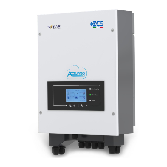
3. Installation 3.1. Product Overview Each 3000SP inverter has been rigorously inspected prior to packaging and delivery. Do not flip over, shake or jerk the packaging during transport. Before opening the box, please check that the packaging of the product is intact and has not been damaged or tampered with. - Page 11 Figure 2 – Views of the 3000SP storage inverter and mounting bracket 3.2. Contents of the packaging Carefully check the contents of the packaging before installation, making sure that no element inside the packaging is missing or damaged. The package should contain the following components: 8 expansion plugs and 1 Storage inverter 1 mounting bracket...
-
Page 12: Installation Environment
2 current transformers 2 CT terminals 1 communication cable 1 quality certificate 1 warranty certificate 1 user manual Figure 3 – Components and accessories inside in the packaging 3.3. Installation environment For correct functioning of the system, the inverter and batteries must be installed in an environment with the following characteristics: •... - Page 13 To screw and unscrew screws for the Screwdriver various connections Wire stripper To prepare the cables for wiring To screw the inverter to the wall- 4 mm Allen key mounting bracket Crimping tool To crimp the power cables To check the voltage and current Multi-meter values To mark the wall for better fixing...
-
Page 14: Wall Installation Position
3.5. Wall installation position The 3000SP storage inverter must be installed vertically on the wall (to ensure rapid and effective heat dissipation) or at an inclination not exceeding 15°. Also make sure that the position where the inverter is installed is not directly exposed to sunlight or subject to the accumulation of snow so as to prevent damage to the internal components of the machine. - Page 15 Figure 6 – Instructions for fixing the bracket to the wall 4) Position the 3000SP storage inverter on the mounting bracket and secure it with the mounting bolt supplied. 5) Secure the grounding connection of the 3000SP by means of the bolt supplied and using the appropriate hole in the heat sink.
-
Page 16: Electrical Connections
Note: for safety reasons, ZCS Spa and/or its partners may not carry out any technical repairs or maintenance work, or move the inverter or battery pack from and to the ground if they are installed at a height of more than 180 cm from the ground. - Page 17 size for the electrical connections. - Battery connection: DC cable with cross-section of AWG8 or AWG6. - Grid or load connection: AC cable with cross-section of AWG12 • Make sure that the neutral wire (N) is connected to the ground wire (PE) when the EPS mode (emergency power supply) is enabled.
-
Page 18: Ct / Rs485 / Ntc Connections
Figure 10 – Connecting the power line of the battery 4.2. CT / RS485 / NTC connections 18 / 58 Manual of 11/06/2019 Rev. 1.8 “User Manual for 3000SP storage inverter” Identificazione: MD-AL-GI-00 Rev. 4.0 del 31.01.18 - Applicazione: GID... - Page 19 Figure 11 – Wiring diagram of the 3000SP storage inverter in a system powered by renewable energy 1) Correctly position the two current sensors (CT): - the CTa for measuring the energy exchanged with the grid must be positioned at the output of the exchange meter (utility side) and must include all the phase cables entering or leaving the meter.
- Page 20 CT cable Extension (network cable) Connection to 3000SP orange / orange white / brown / brown white green / green white / Black blue / blue white Figure 13 – Connecting the CT cables of the current sensors 3) Unscrew the 4 screws (A) of the central cover with a star screwdriver (figure 13). 4) Remove the waterproof cover (B), loosen the cable gland (C), and then remove the stopper (G).
- Page 21 NOTE: for correct connection between the inverter and batteries, please refer to the relevant procedure or manual. Figure 14 – End of communication cable with inverter-side terminal and battery-side terminal 7) Route the temperature probe cable through the cable gland, then insert the terminal into the NTC input and connect the other end to the battery (this should only be done for lead-acid batteries or batteries not equipped with BMS).
- Page 22 Figure 16 – Connecting the network cable to the GRID terminal 4.4 Connecting the critical loads (EPS function) In the event of a power failure, if the EPS function is enabled and the batteries are sufficiently charged, the 3000SP inverter will go into EPS mode (emergency power), drawing energy from the battery pack and supplying power to the critical loads via the LOAD port.
- Page 23 The procedure for connecting the LOAD input to the inverter terminal board is identical to that for connecting the GRID port shown in section 4.3, with the only difference being that the phase, neutral and ground cables must be connected to the port marked LOAD. For more information, please consult the specific procedure available on the website www.zcsazzurro.com.
-
Page 24: Buttons
5. Buttons and Indicator lights Figure 19 – Buttons and indicator lights of the 3000SP inverter 5.1. Buttons • Press “Menu/Back” to enter the previous screen or main menu. • Press “Up” for the upper menu option or to increase the value. •... -
Page 25: Operating Status
5.3. Operating status Green discharging Green charging Operating status Red alarm light light light Discharging Steady Discharging control Intermittent Charging Steady Charging control Intermittent Standby Intermittent Intermittent EPS status Steady Steady Alarm Steady 25 / 58 Manual of 11/06/2019 Rev. 1.8 “User Manual for 3000SP storage inverter” Identificazione: MD-AL-GI-00 Rev. -
Page 26: Operation
6. Operation 6.1. Preliminary checks Please carry out the following checks before commissioning the inverter. 1) The 3000SP inverter must be securely attached to the wall mounting bracket. 2) The polarity of the battery cables must be correct and the power cables must be connected securely. 3) The DC circuit breaker must be correctly connected between the battery and the 3000SP inverter, and must be set to OFF (only if it has been installed, e.g. - Page 27 In the case of Weco ReSU 4K4 batteries, press the POWER button for one second, making sure that the RUN light turns on. Figure 22 – Front view of a Weco ReSU 4K4 battery In the case of batteries not equipped with BMS, turn ON any DC circuit breaker located between the batteries and the storage inverter.
- Page 28 Code Country Code Country Code Country Germany VDE AR-N4105 Poland Cyprus CEI 0-21 Internal Germany BDEW India Australia Germany VDE 0126 Philippines Spain RD1699 Italy CEI 0-16 New Zealand Turkey UK-G83 America Denmark Greece - islands Slovakia VSD Greece - mainland EU EN 50438 Slovakia SSE Netherlands...
- Page 29 The table below shows the recommended parameters for PYLONTECH US2000B and US2000 PLUS batteries: Number of batteries in parallel Battery type PYLON PYLON PYLON PYLON Capacity 50Ah 100Ah 150Ah 200Ah Maximum charging voltage 53.2V 53.2V 53.2V 53.2V Maximum charging current 25.0A 50.0A 60.0A...
- Page 30 9) Maximum discharging current [A] (only for DEFAULT batteries) Use the “Up” and “Down” keys to set the maximum discharging current for the battery pack connected to the system (check the battery datasheet), press “OK” to move to the next value and confirm. Once the setting has been completed, the system will automatically move to the next section.
-
Page 31: Commissioning
6.3. Commissioning Figure 23 – Main interface After completing the initial settings, switch off the 3000SP inverter by disconnecting the connection line to the electrical grid, and bring the battery switches to the OFF position. Switch the 3000SP back on again by carefully following the steps described below for correct calibration of the current sensors. -
Page 32: Menu
Make sure that the display of the 3000SP storage inverter shows that the power produced by the photovoltaic modules is equal to the sum of the power consumed by the utility, fed in/out from the grid and exchanged with the batteries. If the working mode has not been changed, or if the storage inverter is operating in “Auto mode”: •... - Page 33 1. Battery parameters 1.Battery Parameters 1.Battery Type 7.Max. discharge current (A) 2*.Battery capacity 8*. Min. voltage threshold 3.Depth of discharge 9.Min discharge voltage (V) 4.Max charge current 10*.End-of-discharge V (V) 5.Over-voltage 11*.End-of-charge V (V) threshold 6.Max charging 12.Save threshold (V) Note: settings 2*/8*/10*/11* are only accessible for DEFAULT batteries.
- Page 34 3) Depth of discharge Depth of discharge EPS depth of discharge Select “3. Depth of discharge” and press “OK” to enter the menu for setting the depth of discharge. Press the “Up” and “Down” keys to change the depth of discharge in both normal operating mode and in EPS mode depending on the type of batteries used.
- Page 35 When setting this parameter for Pylontech batteries, refer to the table in section 6.2; for different battery models, refer to the relative datasheet. 7) Maximum discharge current (A) Select “7. Max discharge current (A)” and press “OK” to enter the menu for setting the maximum discharge current.
- Page 36 2. Delete Energy Data Select “2. Delete Energy Data” and press “OK.” The display will show “Enter PWD!” Press “OK” to enter the password “0001” using the “Up” and “Down” keys to select the number and “OK” to move to the next digit. If the display shows “Incorrect, try again!” press the “Menu/Back” key and enter the password again.
- Page 37 A faster way to change the menu language is to press the “Menu/Back” key and “OK” key at the same time. In the firmware version V1.90, the languages available are Chinese, English, Italian, French, German, Slovak and Ukrainian; future firmware updates may add additional languages. 8.
- Page 38 11. Self-test (only for the Italian market) Select “11. Self-test” and press “OK” to enter the self-test interface. Note: this setting is only used in Italy and is therefore visible only if country code 01 or 15 has been set. 11.Self-Test 1.Fast Self-test 2.STD Self-test...
- Page 39 ↓ Wait Test 81>S1 OK! ↓ Wait Testing 81>S2… ↓ Wait Test 81>S2 OK! ↓ Wait Testing 81<S1... ↓ Wait Test 81<S1 OK! ↓ Wait Testing 81<S2... ↓ Wait Test 81<S2 OK! ↓ Press “OK” Self-Test OK! ↓ Press “down” 59.S1 253V 900ms ↓...
- Page 40 ↓ Press “down” 81>.S1 50.5Hz 100ms ↓ Press “down” 81>.S1 49.9Hz 103ms ↓ Press “down” 81>.S2 51.5Hz 100ms ↓ Press “down” 81>.S2 49.9Hz 107ms ↓ Press “down” 81<.S1 49.5Hz 100ms ↓ Press “down” 81<.S1 50.0Hz 105ms ↓ Press “down” 81<.S2 47.5Hz 100ms ↓...
- Page 41 4) Set QV time Select “4. Set QV time” and press “OK” to enter the menu for setting this parameter. The display will show the following: Set:** s ** represents the time to be set in seconds. Use the “Up” and “Down” keys to set the desired value.
- Page 42 The 3000SP will remain in Standby as long as the energy When the energy from the photovoltaic system is greater than produced by the photovoltaic system is less than that requested that requested by the loads, the 3000SP will give priority to by the loads (or the difference is <...
- Page 43 Below are the instantaneous information and values that can be seen by pressing the “Down” key from the main interface. Grid (V) Indicates the voltage of the grid in Volts Indicates the current exchanged with the grid in Ampere (the symbol – in front Grid (A) of the figure indicates a transfer of power to the grid) Frequency...
- Page 44 Below is an example of how it can be applied: a) During the night, between 9.00pm and 6.00am, the mains power has a lower price and therefore it can be used to charge the battery (this feature is not recommended with CEI-201 standard).
-
Page 45: Event List
Set Start Param. Set safety V Set safety Hz Press “OK” and wait for “OK” to appear on the display. Note: for more information and to request the firmware update files, please contact Azzurro ZCS Technical Support toll free... -
Page 46: System Information
2. List of historical events Select “2. List of historical events” and press “OK” to access the information on the history of errors in the memory; in particular, you will be able to view the number of errors, the identification code, and date/time at which they occurred. -
Page 47: Software Update
3000SP inverter firmware. Proceed as follows: 1. Switch off the ZCS 3000SP inverter by disconnecting the AC power and turning off the batteries. If Pylontech batteries are used, set the switches of each battery in the pack to 0. - Page 48 L8 light turns on. If batteries other than those mentioned above are used, start them according to their relevant procedure and power up the ZCS inverter by pressing the appropriate switch installed between the batteries and the inverter. 8. Power up the storage system via the circuit breaker installed.
-
Page 49: Energy Statistics
AC switch and then the switches located on the batteries. Wait 3 minutes and follow the above steps again, starting from point 7. Note: for more information and to request the firmware update files, please contact the Azzurro ZCS Technical... -
Page 50: Technical Specifications
7. Technical specifications Technical specifications 3000SP Battery Connection technical data Type of compatible battery Lithium ion / Lead / Gel / Salty Water, etc. Rated voltage Allowable voltage range 42-58V Recommended battery capacity 50-200Ah Maximum charge/discharge power 3000W Allowable temperature range -10°C/50°C Maximum charge current 65A (programmable) - Page 51 Environmental protection rating IP65 (inverter) Allowable relative humidity range 0…95% Without condensation Maximum operating altitude 2000m Noise level <25db@1m Weight 16kg Cooling Natural convection Dimensions (HxWxD) 532 x 360 x 173mm Display LCD display Warranty 10 years 51 / 58 Manual of 11/06/2019 Rev.
-
Page 52: Troubleshooting And Maintenance
8. Troubleshooting and maintenance 8.1. Troubleshooting This section contains information and procedures on how to troubleshoot any faults and errors that may occur during operation of the 3000SP storage inverter. If you have any problems with the inverter, please follow these steps. Is the inverter located in a clean, dry and properly ventilated place? Is the battery switch ON? Are the cables correctly sized and as short as possible? - Page 53 Voltage on LLC line HW_LLCB ID09 is too high Hardware us_OVP protection trip Boost voltage is too HW_Boost ID10 high. Hardware _OVP protection trip BuckBoost current is HwBuckBo too high. Hardware ID11 ostOCP ID09- ID26: Internal errors of the 3000SP inverter. protection trip Battery current is Switch off the unit by disconnecting the AC and DC...
- Page 54 Grid voltage measurements Consistent between the main ID49 Fault_VGri DSP and the secondary DSP are not aligned Grid frequency measurements Consistent between the main ID50 Fault_FGri DSP and the secondary DSP are not aligned DCI measurements between the main Consistent ID51 DSP and the Fault_DCI...
- Page 55 unrecover ID76 EEPROM_ Unreadable EEPROM unrecover Permanent fault on ID77 RelayFail relays Check that the 3000SP inverter is installed in a place without direct sunlight / other heat sources. Over Internal temperature ID81 Temperatu Check that the 3000SP inverter is installed vertically and is too high.
-
Page 56: Maintenance
Over-temperature ID106-ID107 are battery errors. ID104 BatOTD protection of battery discharge Check the conditions of installation and ventilation of the battery. Alternatively, reduce the charge and Over-temperature discharge current value set. ID105 BatOTC protection of battery If the error persists, contact Technical Support. charge Under-temperature ID106-ID107 are battery errors. -
Page 57: Uninstalling
9. Uninstalling 9.1. Steps for uninstalling the inverter Disconnect the inverter from the AC grid. Disconnect the AC switch (located on the battery or installed on the wall) Wait 5 minutes Remove the DC connectors from the inverter ... -
Page 58: Warranty
10. Warranty Zucchetti Centro Sistemi SpA provides a 10-year product warranty, subject to registration on the website https://www.zcsazzurro.com/it/estensione-garanzia. In any case, the warranty cannot exceed 126 months from the date of delivery of the inverter. During the warranty period, Zucchetti Centro Sistemi S.p.A. guarantees normal operation of the inverter. If the inverter is defective or faulty during the warranty period, contact your installer or supplier.
Need help?
Do you have a question about the Azzurro 3000SP and is the answer not in the manual?
Questions and answers