
Subscribe to Our Youtube Channel
Related Manuals for ZCS 20000TL-G2


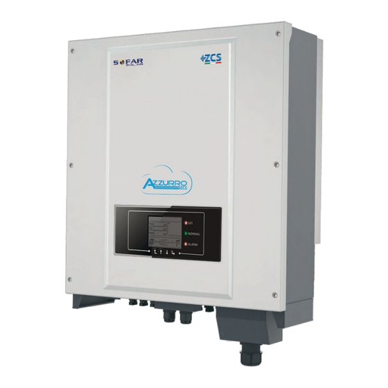
Summary of Contents for ZCS 20000TL-G2
- Page 1 User manual PV Grid-Connected Inverter Product Model: 20K-33KTL-G2 (2018.10.08) www.zcsazzurro.com...
- Page 2 The product , service and features that you purchased are bound by ZCS commercial contract and terms,The product, service and features(or part of them) described in this document may not be in your purchase or usage range. ZCS does not declare or guarantee any content Outline in this document except there are other contractual stipulation.
-
Page 3: Table Of Contents
20~33KTL-G2 20~33KTL-G2 User manual User manual 6 Operation interface Operation and Display Panel Table of contents 6.2 Standard Interface 6.3 Main Interface 7 Trouble shooting and maintenance Trouble shooting Preface 7.2 Maintenance 1 Basic safety information 8 Decommissioning Safety instructions Decommissioning steps 1.2 Symbols and signs 8.2 Package... -
Page 4: 33Ktl-G2
20~33KTL-G2 20~33KTL-G2 User manual User manual Assembly situation requirements Basic safety information Please install and start inverter according to the following sections. Put the inverter in appropriate bearing capacity objects(such as wall and components and so on), to ensure that inverter vertical placed. -
Page 5: Symbols And Signs
20~33KTL-G2 20~33KTL-G2 User manual User manual Operation Signs on the inverter There are some symbols which are related to security on the inverter. Please read and Touching the power grid or the terminal of equipment may lead to die of electric understand the content of the symbols, and then start the installation. -
Page 6: Product Characteristics
20~33KTL-G2 20~33KTL-G2 User manual User manual Intended grid types: 20~33KTL-G2 inverters are compatible with TN-S、 TN-C、 TN-C-S、 TT、 IT grid configurations.For the TT type of electricity grid, the voltage between neutral and earth Product characteristics should be less than 30V. Figure2-2 Overview of the grid configurations Outlines of this chapter TN-S... - Page 7 The specific models of multi-string inverter that this manual is about are divided into four the installation conditions, Designer chooses the proper inverter model according to groups according to the maximum output power ( 20000TL-G2, 25000TL-G2, 30000TL-G2, installation site ,enviroment and whole system integration.
-
Page 8: Function Description
20~33KTL-G2 20~33KTL-G2 User manual User manual Figure2-9 Back view and Bracket dimensions 2.2 Function description Operating Principle 512.0mm 459mm DC power generated by PV array is filtered through string detection board and input board 336mm before entering into Power board. Input board also offer functions such as insulation 14mm impedance detection and input DC voltage / current detection. - Page 9 20~33KTL-G2 20~33KTL-G2 User manual User manual Figure2-10 Electrical block diagram Function module A. Configurable relay The inverter has a configurable switching relay that can be used in various operating conditions set in the dedicated menu. A typical application example is the closing of the contact when an alarm occurs.
-
Page 10: Protection Modules
20~33KTL-G2 20~33KTL-G2 User manual User manual Input voltage derating curve 2.3 Protection modules A. Anti-islanding Output Power vs Input Voltage In the event of a local grid outage by the electricity company, or when the equipment is switched off for maintenance operations, the inverter must be physically disconnected safely, to ensure protection of people 40000 working on the grid, all in accordance with the relevant national standards and laws. -
Page 11: Installation
20~33KTL-G2 20~33KTL-G2 User manual User manual 3.1 Installation Process Figure3-1 Installation flowchart Installation Check before Prepare installation Determine the Start installation tools installation position Outlines of this chapter Installation the rear Installation the Moving the inverter This topic describes how to install the 20~33KTL-G2. panel inverter Installation notes... -
Page 12: Tools
20~33KTL-G2 20~33KTL-G2 User manual User manual 3.3 Tools Table3-1 shows the components and mechanical parts that should be delivered Quantity Description Pictures Prepare tools required for installation and electrical connections. 1PCS 20~33KTL-G2 Table3-1 Shows the components and mechanical parts that should be delivered Tool Model Function... -
Page 13: Determining The Installation Position
20~33KTL-G2 20~33KTL-G2 User manual User manual 3.4 Determining the Installation Position Tool Model Function Determine an appropriate position for installing the 20~33KTL-G2. R 45 2PCS Comply with the following requirements when determining the installation position: Figure 3-2 Installation position requirements Cable cutter Used to cut power cables Crimping tools... -
Page 14: Moving The 20~33Ktl-G2
20~33KTL-G2 20~33KTL-G2 User manual User manual Many 20~33KTL-G2 installation Figure3-4 Moving the 20~33KTL-G2 (2) Step 2 Lift the 20~33KTL-G2 from the packing case and move it to the installation position. To prevent device damag and personal injury, keep balance when moving the 200mm 20~33KTL-G2 because the 20~33KTL-G2 is heavy. -
Page 15: Electrical Connections
20~33KTL-G2 20~33KTL-G2 User manual User manual Step 4 Putting the inverter hook on the rear panel. Step 5 Using an M6 screw back and inverter bottom fastening, to ensure safety. Electrical Connections Step 6 Putting the rear panel and inverter to lock together, In order to ensure the safety (the user can select lock according to the actual situation). -
Page 16: Electrical Connection
20~33KTL-G2 20~33KTL-G2 User manual User manual 4.1 Electrical connection Prerequisites: The PGND cables are prepared (8 AWG outdoor power cables are recommended for Figure4-1 Shows the flowchart for connecting cables to the 20~33KTL-G2 grounding purposes). Connect AC Output power Start Connect PGND Cables Cables Procedure:... -
Page 17: Connecting Ac Output Power Cables
Step 2 Remove the insulation layer of an appropriate length according to figure 4-6, then and the breakers. insert the AC output cable though the PG waterproof cable gland. Table4-1 Figure4-6 AC Output Cable schematic diagram Type 20000TL-G2 25000TL-G2 30000TL-G2 33000TL-G2 ≥ ≥... -
Page 18: Connecting Communications Cables
20~33KTL-G2 20~33KTL-G2 User manual User manual 4.4 Connecting Communications Cables Procedure Step 1 Remove the insulation layer of an appropriate length from the shielded network cable Connecting Communications Port using a wire stripper. 20~33KTL-G2 inverter has 3 communication ports: 2 RS485 ports, 1 WiFi/GPRS port, as shown Step 2 Open 20~33KTL-G2 lower cover and insert the shielded network cable into the cable below screw nut, seals, screw nut. - Page 19 20~33KTL-G2 20~33KTL-G2 User manual User manual WiFi/GPRS communication Step 3 Fix the WiFi/GPRS module using two screws. Monitor the inverter via WiFi/GPRS module. Figure 4 15 WIFI Connecting Communications Cables(3) Procedure: Step 1 Remove waterproof cover using screwdriver. Figure 4 13 WIFI Connecting Communications Cables(1) Note: Follow the WiFi/GPRS manual to start monitoring your inverter.
- Page 20 20~33KTL-G2 20~33KTL-G2 User manual User manual WIFI If only one 20~33KTL-G2 is used, use a communication cable with waterproof RJ45 connectors, and choose either of the two RS485 ports. By the WIFI interface, transfer the inverter power output information, alarm information, operation state to the PC terminal or local data acquisition device , then uploaded to the Figure 4 16 A single 20~33KTL-G2 connecting Communications server (such as S-WE01S).
-
Page 21: Connecting Dc Input Power Cables
PV array should be excellent performance, reliable quality. The open circuit voltage of PV must be less than Maximum DC input voltage of inverter, The output voltage of the solar array must be consistent with the MPPT voltage range. Table4-5 MPPT voltage range 20000TL-G2 25000TL-G2 30000TL-G2 33000TL-G2... - Page 22 20~33KTL-G2 20~33KTL-G2 User manual User manual Context DC connection between inverter and string panel should be specified PV cable. Line voltage Table 4-6 Recommended DC input cable specifications drop should be less than 2% from junction box to inverter.Inverter is recommended to be Cross-Sectional Area (mm) installed on or near PV panel bracket , which can save cable and reduce DC loss.
- Page 23 20~33KTL-G2 20~33KTL-G2 User manual User manual Step 3 Insert the positive and negative power cables into corresponding cable glands. Procedure Step 4 Insert the stripped positive and negative power cables into the positive and negative Step 1 Remove cable glands from the positive and negative connectors. metal terminals respectively and crimp them using a clamping tool.
-
Page 24: Safety Check
20~33KTL-G2 20~33KTL-G2 User manual User manual Follow-up Procedure To remove the positive and negative connectors from the 20~33KTL-G2, insert a removal wrench into the bayonet and press the wrench with an appropriate strength, as shown in Commissioning of inverter Figure 4-29. Before removing the positive and negative connectors, ensure that the DC 5.1 Safety inspection before commissioning SWITCH is OFF. -
Page 25: Operation Interface
20~33KTL-G2 20~33KTL-G2 User manual User manual 6.2 Standard Interface LCD standard interface is used to display inverter states、information and parameter setting etc. Operation interface Outlines of this chapter Introduce the dispaly operation buttons and LED light of 20~33KTL-G2. 6.1 Operation and Display Panel Buttons and Indicator lights 、... -
Page 26: Main Interface
20~33KTL-G2 20~33KTL-G2 User manual User manual Inverter states includes: wait、check、normal、fault and permanent Wait : Inverter is waiting to Check State at the end of reconnection time. In this state, the PV voltage is more than 250V, grid voltage value is between the max and min limits and so on;... - Page 27 20~33KTL-G2 20~33KTL-G2 User manual User manual Set Country Code (A) “Enter Setting” Interface as below: Users press “Back” button to enter “1.Enter setting” interface, Press OK button to enter main setting interface. Enter “4.Set Country Code” by pressing “Up” button Or “Down” button, 1.Enter Setting press “OK”...
- Page 28 20~33KTL-G2 20~33KTL-G2 User manual User manual On-Off Control Relay Command Definition: Users press ''Back'' button to enter ''1.Enter Setting'' interface,Press ''OK'' button to enter main setting interface.Enter ''5.On-Off Control'' by pressing ''UP'' button or the relay switches whenever a connection to (or a disconnection from) the grid occurs.
- Page 29 20~33KTL-G2 20~33KTL-G2 User manual User manual Set inputmode Set Insulation User can change the Insulation protection point by the LCD. First the User need to copy the. Input mode selection:20~33KTL-G2 has 2 MPPT, The two MPPT can run independently, and TXT file which is used to change the Insulation protection point to the SD card .
- Page 30 20~33KTL-G2 20~33KTL-G2 User manual User manual Setting P(f) (C) “SystemInfo” Interface as below: Users press Back button to enter “1.Enter setting” interface, Press OK button to enter main “ ” setting interface. Enter “19. Setting P(f)” by pressing “Up” button Or “Down” button, then 3.SystemInfo press “OK”...
- Page 31 20~33KTL-G2 20~33KTL-G2 User manual User manual Country (D) System Time Users press Back button and Up button or Down button to enter “3. SystemInfo” “ ” “ ” “ ” Press the “Back” button and “Up” button or “Down” key in the standard user interface to interface, then Press “OK”...
-
Page 32: Trouble Shooting And Maintenance
20~33KTL-G2 20~33KTL-G2 User manual User manual PVUVP Check whether too few PV modules are series ID05 The input voltage is too low connected in a PV string, thus the voltage(Vmp) of the PV string is lower than the minimum operating voltage of inverter. - Page 33 20~33KTL-G2 20~33KTL-G2 User manual User manual ID25 If the PV array configuration is correct (no ID5 fault), ID65 UnrecoverHwAcOCP The grid current is too ID65-ID70 are internal faults of inverter, turn OFF the BusUVP The bus voltage Is too low high,and has cause “DC switch”, wait for 5 minutes, then turn ON the the possible cause is that the solar irradiance is too...
-
Page 34: Maintenance
20~33KTL-G2 20~33KTL-G2 User manual User manual ID90 Fan3 alarm The fan3 is fault Check whether the internal fan is not working, if so, replace the fan, if the alarm still exits after the replacement, please contact technical support. Decommissioning ID91 Fan1 alarm The fan1 is fault Check whether the external fan with blue heat-shrink... -
Page 35: Technical Data
20~33KTL-G2 20~33KTL-G2 User manual User manual 9.2 Output parameter (AC) Parameter 20000TL-G2 25000TL-G2 30000TL-G2 33000TL-G2 Technical data Rated power 20000W 25000W 30000W 33000W Max. AC power 22000VA 27500VA 33000VA 36300VA Outlines of this chapter Rated AC voltage 3/N/PE,230/400Vac This topic lists the technical specifications for all 20~33KTL-G2 inverters. -
Page 36: General Data
20~33KTL-G2 20~33KTL-G2 User manual User manual 9.4 General Data 20000TL-G2 25000TL-G2 30000TL-G2 33000TL-G2 Parameter Quality Assurance Ambient temperature -25℃…+60℃ range Allowable relative 0…100% no condensing 20~33KTL-G2 humidity range Topology Transformerless Degree of protection I P65 Max. operating altitude <2000m Noise <30dB...
Need help?
Do you have a question about the 20000TL-G2 and is the answer not in the manual?
Questions and answers