Table of Contents
Advertisement
Advertisement
Table of Contents

Subscribe to Our Youtube Channel
Related Manuals for ZCS HYDxxxxES Series


Summary of Contents for ZCS HYDxxxxES Series
- Page 1 HYD 3000/3600/4000/5000/6000-ES User Manual 2018-10-19 Version V1.1...
-
Page 2: Table Of Contents
CONTENT 1. HYD-ES inverter Introduction............................3 2. Safety Notes ................................. 4 2.1. Safety Notes ..............................4 2.2. Installation and Maintenance Notes......................... 4 2.3. Signs on the inverter ............................5 3. Installation ................................... 7 3.1. Product Overview ............................. 7 3.2. Packing List ............................... 8 3.3. -
Page 3: Hyd-Es Inverter Introduction
1. HYD-ES inverter Introduction The HYD-ES hybrid inverter is used in PV system with battery storage. Energy produced by the PV system will be optimized for maximum self-consumption. The HYD-ES inverter can work in auto or time-of-use (TOU) mode, When in auto mode, the HYD-ES inverter will charge surplus PV energy into the battery &... -
Page 4: Safety Notes
2. Safety Notes Before installation, please make sure you read & understand this manual. The HYD-ES inverter strictly comply with safety rules of design and testing. During the installation, operation and maintenance, operators should abide by local safety regulations. Improper operation may cause an electric shock, injury and/or damage equipments and properties. -
Page 5: Signs On The Inverter
be kept in a cool, dry, and ventilated environment. Battery maintenance operators shall have the knowledge and technical skill for battery maintenance; All batteries connected in parallel should be of the same model and have same firmware version. This pay attention to this requirment particularly when replacing batteries or modifying an existing energy storage system. - Page 6 Earth terminal. Please read this manual before installing ZCS HYD-ES inverter. This indicates the degree of protection of the equipment according to IEC standard 70- 1 (EN 60529 June 1997). Positive pole and negative pole of the DC voltage (PV & Battery).
-
Page 7: Installation
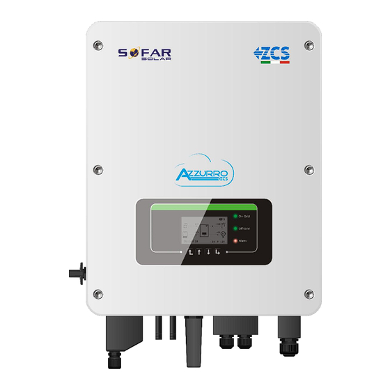
3. Installation 3.1. Product Overview HYD-ES inverter is 100% strictly inspected before package and delivery. It is forbidden to put the HYD-ES inverter upside down during delivery. CAUTION Please check the product package carefully before installation. Fig. 2 HYD-ES inverter overview DC switch Current transformer port Battery input terminals... -
Page 8: Packing List
3.2. Packing List Inspect the package and fittings carefully before installation. You should have the following fittings: Mounting Bracket × 1 M5 screw × 2 Battery terminal × 2 AC terminal × 6 M6 flat washer × 8 CT terminal × 2 Terminal cap ×... -
Page 9: Installation Tools
Maximum altitude: 2000m 3.4. Installation Tools The following tools shall be prepared before installation: Tool Model Function Hammer drill Used to drill holes on the wall Recommend drill dia.6mm Screwdriver wiring Wire stripper Strip wire Turn the screw to connect rear panel 4mm Allen Key with inverter Crimping tools... -
Page 10: Installation Position
Safety glasses Operators wear Anti-dust respirator Operators wear 3.5. Installation Position HYD-ES inverter should be vertically mounted (to ensure good heat dissipation), please choose a position without direct sunlight and/or snow accumulation to install HYD-ES inverter. Ensure that the installation position is well- ventilated. -
Page 11: Mount Hyd-Es Inverter
3.6. Mount HYD-ES inverter Step 1: Put the mounting bracket properly on the wall, mark these 8 drill holes using a marker pen. Drill 8 holes (drill bit 6mm) on the wall. Step 2: Insert the expansion screw vertically into the hole, note the insertion depth. (not too shallow or too deep) Step 3: Fix the mounting bracket on the wall using bolts &... -
Page 12: Electrical Connection
4. Electrical Connection CAUTION High voltages in power conversion circuits. Lethal hazard: risk of electric shock or serious burns. All work on the PV modules, inverters, and battery systems must be carried out by qualified personnel only. Wear rubber gloves and protective clothing (protective glasses and boots) when working on high voltage/high current systems such as INVERTER and battery systems. -
Page 13: Battery Connection
4.1. Battery Connection Fig. 6 Battery connection (Measure battery wires polarity/voltage before connection) Step 1: Loosen 4 screws (A) using a screwdriver (Fig. 6); Step 2: Remove the waterproof cover (B), loosen the cable gland (C), and then remove the stopper (G); Step 3: Pass the battery wires (F) through the cable gland, then connect battery wires using OT terminal (E);... - Page 14 Step 2 Insert crimped PV positive and negative power cables into corresponding PV connectors 3. Positive connector 4. Negative connector Fig. 8 prepare PV positive and negative connectors Step 3 Make sure the DC voltage of each PV string is less than 600V DC and polarities of PV power cables are correct.
-
Page 15: Ct / Can / Rs485 / Ntc Connection
Aggiungere pag 15 di manual italiano 4.3. CT / CAN / RS485 / NTC connection (for Pylontech battery) The CT (Current transformer) measures the value and direction of AC current. Refer to Fig. 11 for the correct connection of CTa. Fig. - Page 16 Fig. 12 CT / CAN / RS485 / NTC connection Step 3: Loosen 4 screws (part A) using a screwdriver (Fig. 12) Step 4: Remove the waterproof cover (part B), loosen the cable gland (part C), then remove the stopper (part G) Step 5: Pass the CT cable through the cable gland, connect CT cable to CT terminal, then insert CT terminal into corresponding ports.
-
Page 17: Grid Connection
Fig. 13 NTC connection Step 7: fasten the waterproof cover using 4 screws. If battery different than Pylontech are used contact ZCS technical support. 4.4. Grid Connection Step 1: Loosen 4 screws (part A) using a screwdriver (fig. 14) Step 2: Remove the waterproof cover (part B), loosen the cable gland (part C), then remove the stopper (part G) Step 3: Route a 3-wire power cable through GRID cable gland, then connect the 3 wires to the corresponding terminal blocks. -
Page 18: Critical Load Connection (Eps Function)
4.5. Critical Load Connection (EPS function) Critical load: in case of power outage, if EPS function is enabled, HYD-ES inverter will work in EPS (Emergency Power Supply) mode, utilize the PV power & energy stored in the battery to supply power to critical load via the LOAD connection output. -
Page 19: Buttons And Indicator Lights
Fig. 15 Change-over Switch connections 5. Buttons and indicator lights 19 / 45... -
Page 20: Buttons
Fig 16. Buttons and indicator lights 5.1. Buttons: press “Back” to the return to the previous menu or enter the main interface; press “Up” to the go to the upper menu option or to increase a value by 1; ... -
Page 21: Operation
6. Operation 6.1. Double Check Please double check the following items before operation. HYD-ES inverter is firmly fastened to the mounting bracket on the wall; PV+/PV- wires are firmly connected, polarity and voltage are correct; BAT+/BAT- wires are firmly connected, polarity and voltage are correct; GRID / LOAD cables are firmly / correctly connected;... - Page 22 the following parameters should be set before HYD-ES inverter starts to operate. 1)Set system time 8)*Set min discharge voltage 2)Set country 9)*Set max discharge current 3)Select battery type 10)*Set min protect voltage 4)*Set battery capacity 11)*Set discharge depth 5)*Set max charge voltage 12)*Set empty discharge voltage 6)*Set max charge current 13)*Set full charge voltage...
-
Page 23: Commissioning
6. SOLTARO SL-3KWH / SL-1KWH If you’re using “3. DEFAULT” battery type additional setting information related to the batteries are required. Contact ZCS technical support for instruction on how to complete the batteries configuration. 6.3. Commissioning The main interface: Fig 17. Main interface... -
Page 24: Menu
By default the HYD-ES inverter configured to work in “Auto Mode”. When in this configuration the system will operate as follow: While “PV Production” > “Home Consumption” If the battery is not full. HYD-ES inverter will charge the battery. While “PV Production” < “Home Consumption” If the battery is not empty HYD-ES inverter will discharge the battery and provide power to the load. -
Page 25: Basic Setting
Main Interface Press “Back” 1.Basic Setting “Up” ↑ 2.Advanced Setting 3.Event List “Down”↓ 4.System Information 5.Energy Statistic 6.Software Update 6.4.1. Basic setting: 1.Basic Setting Press “OK” 1.Language 2.Time Up” ↑ 3.Energy Storage Mode 4.PV Input Mode “Down”↓ 5.EPS Mode 6.Communication Addr. 7.Auto Test 1. - Page 26 “Up” ↑ 2. Time-of-use Mode 3.Timing Mode “Down”↓ 4. Passive Mode 1) Set Self-use Mode Select “1. Self-use Mode”, then press “OK”. In Self-use mode, HYD-ES inverter will automatically charge & discharge the battery. If PV generation = LOAD consumption ( P <...
- Page 27 2) Set Time-of-use Mode (only for country where this operation mode is allowed) Time-of-use Mode allow to force a battery charge from the grid even if the PV production is lower than the household consumption. Select “2. Set Time-of-use Mode”, and then press “OK” to enter Set Time-of-use mode menù. Set Time-of-use Mode Rules.
- Page 28 At which power the battery should be discharged. 4) Set Passive Mode Select “4. Set Passive Mode”, and then press “OK”. For more detailed information, please ask ZCS technical support to get a copy of passive mode communication protocol. 4. PV Input Mode PV input mode selection: The HYD-ES inverter has 2 MPPT channels.
- Page 29 5. EPS Mode 1.Enable EPS Mode 1.EPS Mode Control 2.Disable EPS Mode 5. Set EPS Mode ***S() 2.Set EPS Changeover Time(default 20ms) If PV generation > LOAD consumption ( P > 100W), If PV generation = LOAD consumption, HYD-ES Δ HYD-ES inverter will charge battery.
- Page 30 6. Communication Addr. Select “6. Set Communication Addr.”, press “OK”. Press “Up” or “Down” to change the 1 digit, press “OK” to switch to next digit, after changing the 485-communication address (default :01), press “OK”. 7. Auto Test (ONLY for Italian Market) Select “7.
- Page 31 Testing 81<S1... ↓ Wait Test 81<S1 OK! ↓ Wait Testing 81<S2... ↓ Wait Test 81<S2 OK! ↓ Press “Ok” Auto Test OK! ↓ Press “Down” 59.S1 threshold 253V 900ms ↓ Press “Down” 59.S1: 228V 902ms ↓ Press “Down” 59.S2 threshold 264.5V 200ms ↓...
-
Page 32: Advanced Setting
3) PF Time Setting Select “3. PF Time Setting”, then press “OK”. The following will be shown on the display: Set: *. *** s Press “Up” or “Down” to change the 1 digit, press “OK” to switch to next digit. After changing all digits, press “OK”. 4) QV Time Setting Select “4. - Page 33 1. Battery Parameter 1.Battery Parameter 1)Battery Type 7)Max Discharge (A) 2)*Battery Capacity 8)*Low (V) Protection “Up” ↑ 3)Discharge Depth 9)*Min Discharge (V) 4)Max Charge (A) 10)*Empty Discharged (V) “Down”↓ 5)*Over (V) Protection 11)*Full Charged (V) 6)*Max Charge (V) 12)Save Note: 2)*, 5)*, 6)*, 8)*, 9)*, 10)* and 11)* settings are only if DEFAULT battery type was selected. 1) Battery Type (refer to Set battery type)
- Page 34 Select “5. Over (V) Protection” and press “OK. Press “up” or “down” to change the 1 digit, press “ok” to confirm the value and move to next digit. Input the value of Over (V) Protection per battery specification. Press “OK”. 6) *Max.
- Page 35 HYD-ES inverter to activate the battery right away. 8. Safety Param. 9.Safety Param. 1.Set START Parameters “Up” ↑ 2.Set Safety Voltage 3.Set Safety Frequency “Down”↓ 4.Set Insulation Please contact ZCS technical support for more information. 35 / 45...
-
Page 36: Event List
6.4.3. Event List 3.Event List 1.Current Event List “Up” ↑ 2.History Event List “Down”↓ Event list of HYD-ES inverter, including current event list and history event list. 1) Current Event List Select “1. Current Event List”, press “OK” to check the current events. 2) History Event List Select “2. -
Page 37: Energy Statistic
Safety Param.(1) OFP 1 OFP 2 UFP 1 UFP 2 Safety Param.(2) OVP 10mins 6.4.5. Energy Statistic: 5.Energy Statistic Today ***KWH Load ***KWH Export ***KWH Import ***KWH “Up”↑ Charge ***KWH Discharge ***KWH Week ***KWH “Down”↓ Load ***KWH Export ***KWH Import ***KWH “Up”↑... -
Page 38: Software Upgrade
Step 2 Press the SD card and take it out. Insert the SD card into a micro-SD card reader, then insert micro-SD card reader into a PC; (NOTE: micro-SD card reader & PC are not provided by ZCS). Step 3 Format the SD card. Copy the “firmware” folder to the SD card. -
Page 39: Technical Data
7. Technical Data Model HYD 3000-ES HYD 3600-ES HYD 4000-ES HYD 5000-ES HYD 6000-ES Battery Parameters Battery Type Lead-acid, Lithium-ion Nominal battery voltage Battery voltage range 42 - 58V Lithium:(according to BMS), General 46.0V Min discharge voltage Lead acid: 46.0V Lithium-ion:(according to BMS), Max 58V Max charge voltage Lead acid: 58V... -
Page 40: System Parameters
Max output current 13.7A 18.2A 22.8A 27.3A Nominal grid voltage & 220V,230V,240V, 44 – 55Hz or 54 – 66Hz frequency AC voltage range 180 – 276V (according to local authority requirements) <3% Power factor 1default (+ / - 0.8 adjustable) Inrush current 0.8A / 1us Max output fault current... -
Page 41: Troubleshooting
HW_Boost_OV Boost voltage is too high and has ID10 triggered hardware protection If no, please contact ZCS technical support. HwBuckBoostO BuckBoost current is too high and ID11 has triggered hardware protection The battery current is too high and... - Page 42 LLCBus voltage is too high Bus voltage is too high and has ID26 SwBusOVP triggered software protection If the fault occurs frequently, please contact ZCS ID27 BatOCP Battery current is too high technical support. ID28-ID31 are internal faults of HYD-ES inverter,...
- Page 43 Check whether the problem is solved. ConsistentFault ID50 between the master DSP and slave _Fgrid If not, please contact ZCS technical support. DSP is not consistent The Dci sampling value between ConsistentFault ID51 the master DSP and slave DSP is...
- Page 44 The bus voltage is too high and has ID66 5 minutes, then switch ON the HYD-ES inverter. cause unrecoverable fault Check whether the problem is solved. BitEPSunrecove If no, please contact ZCS technical support. Unrecoverable fault of battery ID67 overcurrent in EPS mode BatOcP Check the...
- Page 45 Check whether the problem is solved. ID96 RTCFault RTC clock chip is fault If no, please contact ZCS technical support. Normally ID98 is caused by loose SD card holder. Click & remuve SD card, press SD card holder then insert card back.
Need help?
Do you have a question about the HYDxxxxES Series and is the answer not in the manual?
Questions and answers