Juniper E Series Hardware Manual
Routing platforms
Hide thumbs
Also See for E Series:
- Installation and user manual (242 pages) ,
- Hardware manual (175 pages) ,
- Configuration manual (312 pages)

Related Manuals for Juniper E Series


Summary of Contents for Juniper E Series
- Page 1 E-series Routing Platforms Hardware Guide Release 5.2.x Juniper Networks, Inc. 1194 North Mathilda Avenue Sunnyvale, CA 94089 408-745-2000 www.juniper.net Part Number: 162-00908-00, Revision A00...
- Page 2 Juniper Networks is registered in the U.S. Patent and Trademark Office and in other countries as a trademark of Juniper Networks, Inc. ERX, ESP, E-series, Internet Processor, J-Protect, JUNOS, JUNOScript, JUNOSe, M5, M7i, M10, M10i, M20, M40, M40e, M160, M-series, NMC-RX, SDX, T320, T640, and T-series are trademarks of Juniper Networks, Inc.
- Page 3 Users should ensure for their own protection that the electrical ground connections of the power utility, telephone lines and internal metallic water pipe system, if present, are connected together. This precaution may be particularly important in rural areas. Caution: Users should not attempt to make such connections themselves, but should contact the appropriate electric inspection authority, or electrician, as appropriate.
- Page 4 EC Declaration of Conformity The EC Declaration of Conformity is available at the end of this manual. Voluntary Control Council for Interference (VCCI) Statement for Japan...
- Page 5 Juniper Networks’ written consent. In any action based on such a claim, Juniper Networks may, at its sole option, either: (1) obtain for you the right to continue using the Program, (2) replace or modify the Program to avoid the claim, or (3) if neither (1) nor (2) can reasonably be effected by Juniper Networks, terminate the license granted hereunder and give you a pro rata refund of the license fee paid for such Program, calculated on the basis of straight-line depreciation over a five-year useful life.
- Page 6 Program and Juniper Networks has provided or offers to provide such release to you for its then current license fee, or (ii) use or combination of the Program with programs or data not supplied or approved by Juniper Networks if such use or combination caused the claim.
-
Page 7: Table Of Contents
Table of Contents About This Guide xiii E-series Routers .................... xiii Audience....................... xiii Conventions....................xiv Documentation ....................xv MIBS....................... xvi Release Notes ..................xvi Abbreviations ..................xvi Web Access .................... xvi Comments About the Documentation ............xvii Contacting Customer Support ..............xvii Part 1 Installing and Using E-series Routers Chapter 1... - Page 8 Unpacking ERX-14xx Models ................. 21 Unpacking ERX-7xx Models and ERX-310 Routers......... 22 Inspecting E-series Router Components and Accessories ....... 23 If You Detect or Suspect Damage..............23 Contacting Juniper Networks................23 The Next Step ....................23 Chapter 3 Installation Guidelines and Requirements Your Preinstallation Responsibilities ..............
- Page 9 Table of Contents Removing a Line Module, SRP Module, or SRP I/O Module ......48 Installing Components for Line Module Redundancy ........50 Installing the Line Modules ..............50 Installing the Redundancy Midplane ............51 Installing the I/O Modules ................ 52 Verifying the Installation................
- Page 10 E-series Hardware Guide Chapter 9 Maintaining E-series Routers Required Tools and Items ................83 Storing Modules and Components ..............84 Cleaning the System ..................84 Upgrading NVS Cards on SRP Modules............84 Upgrading a System That Contains One SRP Module....... 85 Upgrading a System That Contains Two SRP Modules ......
- Page 11 Table of Contents Chapter 12 Module Specifications Module Functionality..................117 Module Specifications ..................125 I/O Module Specifications................128 Cable Lengths for X.21/V.35 Cables............144 Chapter 13 Protocol Support Channelized OCx/STMx Modules..............145 Channelized T1 and E1 Modules ..............147 Channelized T3 Modules ................148 Ethernet Modules ..................149 HSSI Modules ....................150 OCx/STMx ATM Modules................152 OCx/STMx POS and OC48 Modules .............153...
- Page 12 E-series Hardware Guide Task 7: Copy the Software Release File ...........180 Task 8: Save the Current Configuration ...........180 Task 9: Reboot the System..............181 Installing Software in Boot Mode ............181 Task 1: Obtain the Required Information ........182 Task 2: Divert Network Traffic to Another System ......182 Task 3: Access the Boot Mode ............182 Task 4: Assign an IP Address............182 Task 5: Configure Access to the Network Host ........183...
-
Page 13: About This Guide
About This Guide This E-series Routing Platforms: Hardware Guide provides the information you need to install and start the E-series router. If the information in the latest E-series Release Notes differs from the NOTE: information in this guide, follow the E-series Release Notes. The E-series router is shipped with the latest system software installed. -
Page 14: Conventions
E-series Hardware Guide Conventions Table 1 defines notice icons used in this guide, and Table 2 defines text conventions used throughout the book, except for command syntax. Table 3 provides command syntax conventions used primarily in the JUNOSe Command Reference Guide. For more information about command syntax, see JUNOSe System Basics Configuration Guide, Chapter 2, Command Line... -
Page 15: Documentation
HTML files, you can also access PDF files of individual chapters and appendixes. The documentation is also available on the Web. You can order a set of printed documents from your Juniper Networks sales representative. The document set comprises the following books: E-series Hardware Guide–... -
Page 16: Mibs
A complete list of abbreviations used in this document set, along with their spelled-out terms, is provided in the JUNOSe System Basics Configuration Guide, Appendix A, Abbreviations and Acronyms. Web Access To view the documentation on the Web, go to: http://www.juniper.net/techpubs/ Documentation... -
Page 17: Comments About The Documentation
Document name Document part number Page number Software release version Contacting Customer Support For technical support, contact Juniper Networks at support@juniper.net, or at 1-888-314-JTAC (within the United States) or 408-745-9500 (from outside the United States). xvii Comments About the Documentation... - Page 18 E-series Hardware Guide xviii Contacting Customer Support...
-
Page 19: Installing And Using E-Series Routers
Part 1 Installing and Using E-series Routers... - Page 20 E-series Hardware Guide...
-
Page 21: E-Series Overview
Chapter 1 E-series Overview This chapter provides introductory information about the E-series routers. Topic Page Overview Where E-series Routers Fit In E-series Routers ERX-14xx Models ERX-7xx Models ERX-310 Router E-series Modules Network Management Tools Redundancy Features Overview E-series routers are modular, carrier-class networking devices that deliver performance, reliability, and service differentiation to both business and consumer Internet users. - Page 22 E-series Hardware Guide Figure 1: E-series router communicating over T1/T3 lines Internet Remote Remote T1/T3 Core access access router router router Desktop Desktop Figure 2: E-series router communicating over DSL lines Internet Remote Core access router router Home office DSLAM Home office Desktop In Figure 3, the ERX-310 router is being used as an access router in a small POP...
-
Page 23: E-Series Routers
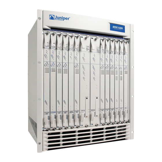
Chapter 1: E-series Overview E-series Routers Five models of E-series routers are available: ERX-1440 router ERX-1410 router ERX-710 router ERX-705 router ERX-310 router All models use the same software. However, the specific model determines the: Combination of line modules supported Conditions for line rate performance of line modules Type, capacity, and number of SRP modules used ERX-14xx Models... - Page 24 E-series Hardware Guide Installation procedures and operating procedures are identical for both systems. All ERX-7xx/14xx models use the same SRP I/O module, but different power input modules are used. The router may look different from the routers shown in the figures in this NOTE: chapter, depending on the line modules in the slots.
-
Page 25: Erx-7Xx Models
Chapter 1: E-series Overview Figure 5: ERX-14xx model, rear view Fan tray module SRP I/O module Power input module Cable management bracket Plenum ERX-7xx Models In the E-series documentation, the term ERX-7xx models refers to both the NOTE: ERX-705 router and the ERX-710 router. The terms ERX-705 router and ERX-710 router refer to the specific models. - Page 26 E-series Hardware Guide The ERX-705 chassis is the same as the ERX-710 chassis (see Figure 6 and Figure 7). The chassis contains seven slots to accommodate modules. Installation procedures and operating procedures are identical for both systems. All ERX-7xx/14xx models use the same SRP I/O module, but different power input modules are used.
-
Page 27: Erx-310 Router
Chapter 1: E-series Overview ERX-310 Router The ERX-310 router is a low-end platform that supports all of the same services as the ERX-7xx/14xx models, but with smaller capacity and scaling capabilities. Like the ERX-7xx/14xx models, the ERX-310 router uses the same software architecture, providing a single IP entry point into the network with the same IP-based protocols and services that are available on other E-series routers. - Page 28 E-series Hardware Guide Figure 9: ERX-310 router, rear view (AC model) I/O module SRP I/O module ESD grounding jack AC power inputs and switches A and B Grounding posts Figure 10: ERX-310 router, rear view (DC model) module SRP I/O module ESD grounding jack DC power inputs...
-
Page 29: E-Series Modules
Chapter 1: E-series Overview E-series Modules The system supports an SRP module and a selection of line modules. You can use any line module for access or uplink. Access line modules receive traffic from low-speed circuits, and the system routes the traffic onto higher-speed uplink line modules and then to the core of the network. -
Page 30: Srp Module
E-series Hardware Guide SRP Module Switch route processor (SRP) modules perform system management, routing table calculations and maintenance, forwarding table computations, statistics processing, configuration storage, and other control plane functions. Each SRP module is a PowerPC-based system with its own memory, nonvolatile disk storage, and power supply (see Figure 12 and Figure 13). -
Page 31: Module Details
Chapter 1: E-series Overview Figure 13: ERX-310 SRP module Ejector Midplane connectors Status LEDs PCMCIA NVS card Board reset button Integrated fabric system processor board NMI button Module Details ERX-7xx/14xx models use up to two redundant SRP modules operating in an active/standby configuration. -
Page 32: Srp Module Redundancy
E-series Hardware Guide SRP Module Redundancy SRP module redundancy is available only for ERX-7xx/14xx models. See Redundancy Features, later in this chapter, for more information. Nonvolatile Storage The PCMCIA slot on the front of the SRP module holds a Type II PCMCIA nonvolatile storage (NVS) card (see Figure 12 and Figure 13). -
Page 33: Line Modules
Chapter 1: E-series Overview Line Modules Line modules process data from different types of network connections. For information about available line modules and which SRP modules support specific line modules, see Chapter 12, Module Specifications. Figure 14 shows a representative line module. For details about installing line modules, see Chapter 5, Installing Modules. -
Page 34: I/O Modules
The system offers a complete SNMP interface for configuration, status, and alarm reporting. The system supports both Standard and Enterprise MIBs (Management Information Bases). The Juniper Networks E-series Enterprise MIB is ASN.1 notated for easy importing into third-party SNMP management applications. For more... -
Page 35: Nvs Cards
Chapter 1: E-series Overview If the primary SRP fails, the redundant SRP module assumes control without rebooting or initializing. (As a consequence, if you upgrade software, you must copy the software to the redundant SRP and reboot it.) For information about configuring and managing SRP module redundancy, see the JUNOSe System Basics Configuration Guide, Chapter 5, Managing Line Modules and SRP... -
Page 36: Line Modules
E-series Hardware Guide Line Modules This section applies to ERX-7xx/14xx models only. ERX-310 routers do not NOTE: offer line module redundancy. ERX-7xx/14xx models support line module redundancy for several line modules. For details about which line modules support redundancy, see Chapter 12, Module Specifications. -
Page 37: Power
Chapter 1: E-series Overview Figure 15: Data flow when a spare line module is active Redundancy I/O module Primary I/O module Ž Œ Midplane Redundancy midplane 1. A packet arrives at the primary I/O module. Spare line module 2. -
Page 38: Fans
E-series Hardware Guide Fans Forced air-cooling keeps the temperature of the E-series modules and components within normal operating limits. In ERX-14xx models, six cooling fans are located in a tray at the top of the router (see Figure 4). In ERX-7xx models, four cooling fans are located in a tray on one side of the router (see Figure 6). -
Page 39: Unpacking And Inspecting E-Series Routers
Unpacking ERX-14xx Models ERX-14xx models come boxed, bolted, and strapped to a skid. For your convenience, Juniper Networks recommends that you unpack the E-series router in the location where you want to install it. Three people are required to install the E-series router in a rack: two to WARNING: lift the system into position and one to screw it to the rack. -
Page 40: Unpacking Erx-7Xx Models And Erx-310 Routers
Unpacking ERX-7xx Models and ERX-310 Routers ERX-7xx models and ERX-310 routers are shipped boxed, but not attached to a skid. For your convenience, Juniper Networks recommends that you unpack the E-series router in the location where you want to install it. -
Page 41: Inspecting E-Series Router Components And Accessories
Contact your Juniper Networks sales representative or reseller. Contacting Juniper Networks Please contact Juniper Networks at 1-888-314-JTAC (within the United States) or 408-745-9500 (from outside the United States), or contact your sales representative if you have any questions or concerns. See Appendix C, Customer Support, for complete contact information. - Page 42 E-series Hardware Guide The Next Step...
-
Page 43: Installation Guidelines And Requirements
Chapter 3 Installation Guidelines and Requirements This chapter reviews preinstallation considerations such as electrical, environmental, and safety compliances for E-series routers. For complete system specifications, refer to Chapter 11, System Specifications. Topic Page Your Preinstallation Responsibilities Environmental Requirements Regulatory Compliances Safety Guidelines Equipment Rack Requirements Cabling Recommendations... -
Page 44: Environmental Requirements
E-series Hardware Guide Environmental Requirements Refer to Chapter 11, System Specifications for complete environmental specifications. Choose a location for the router that is dry, relatively dust free, well ventilated, and air conditioned. If you install equipment in a rack, be sure that the floor is capable of supporting the combined weight of the rack and the installed equipment. -
Page 45: Power Cord Warnings (Ac Model)
Chapter 3: Installation Guidelines and Requirements Do not work on the system or connect or disconnect cables during WARNING: lightning activity. Be sure circuit breakers for the power source are in the OFF position WARNING: before attaching power cables. Before servicing the E-series router, turn off the power. WARNING: Remove jewelry (including rings, necklaces, and watches) before WARNING:... -
Page 46: Equipment Rack Requirements
E-series Hardware Guide Este equipamento tem mais do que um cabo de alimentação. Para que se evitem choques, desligar 2 cabos, ANTES de servir o equipamento. Esta unidad tiene más de un cable de toma de corriente. Desconecte 2 cables ANTES de darle mantenimiento a la unidad, para evitar descargas eléctricas. - Page 47 Chapter 3: Installation Guidelines and Requirements Figure 17: E-series routers installed in a rack ERX-310 router ERX-7xx model Plenum ERX-14xx model Equipment Rack Requirements...
-
Page 48: Mechanical Requirements
A fully loaded rack with three ERX-14xx models must structurally support 300 pounds (136 kilograms). Optional mounting kits are available for 19-inch and 23-inch rack mounting (mid- and front-chassis mounting). Contact your Juniper Networks sales representative for more information. Space Requirements If you use an enclosed rack for an ERX-14xx model, ensure that there is a minimum of 3 inches of clearance between the inner side wall and the router. - Page 49 Chapter 3: Installation Guidelines and Requirements Figure 18: Airflow for E-series routers Air output ERX-310 router and ERX-7xx model Air intake ERX-310 router and ERX-7xx model Air output ERX-14xx model via plenum Air intake ERX-14xx model Air intake ERX-14xx model 3- to 4-ft.
-
Page 50: Cabling Recommendations
E-series Hardware Guide Cabling Recommendations You may want to consult the document GR-63 (LSSGR, FD-15): Network Equipment Building System (NEBS) Requirements: Physical Protection, Issue 1, October 1995 additional cable recommendations. Comply with the following recommendations: Use only shielded cables. Ensure that cable distance and rate limits meet IEEE-recommended maximum speeds and distances for signaling purposes. -
Page 51: Installing E-Series Routers
Chapter 4 Installing E-series Routers This chapter describes how to install E-series routers in a rack. Topic Page Before You Begin Freestanding Installation Rack-Mounted Installation The Next Step Before You Begin Before installing E-series routers, be sure you: Have a plan for installing E-series routers. This plan should consider future expansion of your system. -
Page 52: Rack-Mounted Installation
Power input module Power switches SRP I/O module Rack-Mounted Installation Juniper Networks recommends that you use a standard EIA distribution rack. Refer Equipment Rack Requirements in Chapter 3, Installation Guidelines and Requirements, for detailed rack information. Installation Guidelines Before installing the systems in a rack, consider the following guidelines and refer... - Page 53 Chapter 4: Installing E-series Routers If you install an ERX-14xx model above an ERX-7xx model or ERX-310 router, there is no need to install a plenum between the units because the ERX-7xx models and ERX-310 routers vent air out the side of the chassis. To maintain airflow requirements, a plenum must be installed above an WARNING: ERX-14xx model before any other piece of equipment is installed above the...
- Page 54 E-series Hardware Guide Figure 20: E-series routers installed in recommended order ERX-310 router ERX-7xx model Plenum ERX-14xx model Rack-Mounted Installation...
-
Page 55: Safety Guidelines
Chapter 4: Installing E-series Routers Safety Guidelines Observe the following safety guidelines when mounting the router in a rack. Install equipment in the rack from the bottom upward. This will WARNING: maintain the stability of the rack and reduce the chance that the rack will tip over. Three people are required to install the E-series router in a rack: two to WARNING: lift the system into position and one to screw it to the rack. -
Page 56: Preparing The Equipment Racks
E-series Hardware Guide Preparing the Equipment Racks Following your installation plan, use a tape measure and marking pen to measure and mark space on each equipment rack for each E-series router component. Horizontal spacing should follow NEBS requirements. If you choose not to install a plenum, be sure to include 2 U of space between each chassis to allow for proper exhaust. -
Page 57: Installing Modules
Chapter 5 Installing Modules This chapter describes how to install and remove E-series modules. For information about managing installed modules, see JUNOSe System Basics Configuration Guide, Chapter 5, Managing Line Modules and SRP Modules. Topic Page Overview Safety Guidelines Installing SRP I/O and SRP Modules Installing Line and I/O Modules Removing a Line Module, SRP Module, or SRP I/O Module Installing Components for Line Module Redundancy... -
Page 58: Slot Groups
E-series Hardware Guide Figure 21: Orientation of line modules in E-series routers ERX-7xx model ERX-14xx model ERX-310 router For details about available line modules, see Chapter 12, Module Specifications. For information about compatibility between lines modules and SRP modules, see Table 21 in Chapter 12, Module Specifications. -
Page 59: Slot Groups For The Erx-7Xx Models
Chapter 5: Installing Modules Figure 22: ERX-1410 slot groups Chassis slots 1 2 3 4 8 9 10 11 12 13 Slot Slot Slot Slot group 1 group 2 group 3 group 4 Slot Groups for the ERX-7xx Models A slot group in an ERX-7xx model comprises one slot or two adjacent slots. The groups for an ERX-7xx model consist of the following slots (Figure 23): Slot group 1 –... -
Page 60: Combinations Of Line Modules In Slot Groups
E-series Hardware Guide Combinations of Line Modules In Slot Groups For information about allowed combinations of line modules in slot groups, see JUNOSe System Basics Configuration Guide, Chapter 5, Managing Line Modules and Modules. OC48 Line Modules The ERX-1440 router with the SRP-40G+ SRP module supports OC48 line modules. Other E-series routers do not support OC48 line modules. -
Page 61: Order Of Installation
Chapter 5: Installing Modules Table 4: Grounding jack locations E-series Router Location ERX-14xx model Front: inside front bezel in lower-left corner Rear: upper-right corner ERX-7xx model Rear: lower-right corner ERX-310 router Front: lower-left corner Rear: lower-right corner To protect the modules and slots when installing modules, observe the following guidelines: When handling modules, use an antistatic wrist strap connected to the CAUTION:... -
Page 62: Required Tools And Safety Items
Doing so may cause electric shock and serious burns. Never attempt to repair parts of modules yourself. Only trained WARNING: customer service personnel are authorized to service parts. Call Juniper Networks Customer Service to make arrangements to return defective modules for repair. Installing SRP I/O and SRP Modules SRP modules should be installed in specific slots in each router. -
Page 63: Installing An Srp I/O Module
Chapter 5: Installing Modules Because of different physical dimensions and switch fabric capabilities, SRP NOTE: modules are not interchangeable between systems. For example, the 10-Gbps SRP module used in ERX-7xx/14xx models cannot be used in an ERX-310 router, and vice versa. Install the SRP I/O module before you install the SRP module;... - Page 64 E-series Hardware Guide 4. Remove the SRP module from its antistatic bag. 5. Verify that the ejectors are in the open position, as shown in Figure 25. Figure 25: Ejectors in the open position Œ Opened Closed Closed Œ...
-
Page 65: Installing Line And I/O Modules
Chapter 5: Installing Modules Installing Line and I/O Modules This section describes the procedures for installing line and I/O modules. Install the I/O module before you install the corresponding line module; NOTE: otherwise, after the line module has tried to reboot, its status will be “inactive” when you issue the show version command. -
Page 66: Removing A Line Module, Srp Module, Or Srp I/O Module
E-series Hardware Guide 7. Insert the module into the midplane by simultaneously depressing both ejectors (as shown in Figure 25) and exerting forward pressure on the module. 8. Tighten the module’s captive screws using a Phillips screwdriver. Alternately turn each screw several times before tightening them completely to allow the module to sit correctly. - Page 67 Chapter 5: Installing Modules Figure 26: Ejectors in the closed position Opened Œ Closed Œ Closed Opened 5. Carefully slide the module out of the chassis. 6. Place the module in its antistatic bag. 7. Cover the empty chassis slot with a blank faceplate, and tighten the faceplate’s captive screws using a Phillips screwdriver.
-
Page 68: Installing Components For Line Module Redundancy
E-series Hardware Guide Installing Components for Line Module Redundancy A spare line module provides redundancy for a group of identical line modules for ERX-7xx/14xx models only. The ERX-310 router does not support line module redundancy. NOTE: For line module redundancy to operate, you must install: The line modules, including the spare line module The redundancy midplane The I/O modules, including the spare I/O module... -
Page 69: Installing The Redundancy Midplane
Chapter 5: Installing Modules Installing the Redundancy Midplane To install the redundancy midplane in a redundancy group: If you do not use the halt command before removing or powering down CAUTION: an SRP, the system’s NVS card may become corrupted. 1. -
Page 70: Installing The I/O Modules
E-series Hardware Guide Figure 27: Installing a redundancy midplane Redundancy midplane Installing the I/O Modules To install the I/O modules in a redundancy group: 1. Install the redundancy I/O module in the lowest-numbered slot of the redundancy group. When setting up a redundancy group with line modules, be sure to CAUTION: install the redundancy I/O module in the lowest-numbered slot of the redundancy group. -
Page 71: Verifying The Installation
Chapter 5: Installing Modules Verifying the Installation To verify that the installation is complete: 1. After you have cabled the system for power (see Chapter 6, Cabling E-series Routers), turn on the power switches. The system reboots. 2. Issue the show redundancy command, and verify that the display shows the redundancy hardware. - Page 72 E-series Hardware Guide The Next Step...
-
Page 73: Chapter 6 Cabling E-Series Routers
5. Connect grounding wires to the E-series chassis. 6. Connect the power cables from the power source to the power input module. 7. Connect the line I/O modules to their appropriate network interface. Juniper Networks recommends that you use shielded cables where NOTE: appropriate. - Page 74 E-series Hardware Guide Figure 28: E-series ports and connectors (ERX-14xx model shown) SRP I/O module Alarm leads (slot positions 6 and 7) External timing ports (Europe) External timing ports (North America) FE-8 I/O module (slot 5) OC3-4 OC3-4 FE-8 SINGLE SINGLE MODE MODE...
-
Page 75: Required Tools, Wires, And Cables
Chapter 6: Cabling E-series Routers Required Tools, Wires, and Cables Cabling your system should take only a few minutes. You will need the items listed below and in Table 7 for proper installation. 1/8" flathead screwdriver 3/8" wrench or 3/8" nut-driver No. -
Page 76: Cabling The Srp I/O Module
E-series Hardware Guide Cabling the SRP I/O Module Before powering up the E-series router, you must set up a management console. The console enables you to communicate with your system during the power-up process and to manage your system using the command line interface (CLI). When connecting a console directly to the SRP I/O module, use a cable appropriate for your terminal connector. - Page 77 Chapter 6: Cabling E-series Routers Use shielded cables to connect the external clock sources to the clock NOTE: source input ports. Figure 29: ERX-14xx model SRP I/O module MINOR 26-AWG wire MAJOR CRITICAL E1 75 OHM BNC (Europe) CLOCK IN Wire-wrap connectors (North America, Japan) T1 100 OHM...
-
Page 78: Console Ports
E-series Hardware Guide You can use a wire-wrap gun to attach wires to pins. NOTE: 2. Attach the opposite end of the external timing cable or wires to your network’s clock source A. 3. Repeat steps 1 and 2 for the Clock B connections. Console Ports This section applies to all E-series routers. -
Page 79: Connecting To The Network
Chapter 6: Cabling E-series Routers Connecting to the Network To connect the E-series router to the network: 1. Insert an Ethernet cable (RJ-45) connector into the 10/100Base-T (RJ-45) port on the SRP I/O module until it clicks into place. 2. Connect the other end of the cable to the appropriate Ethernet network for an out-of-band connection. - Page 80 E-series Hardware Guide Table 9: Power input module cables/wires needed Cable/Wire From ERX-14xx models One 10-AWG ground wire Power input module ground Termination ground terminal Two 6-AWG wire leads Power input module Power A Appropriate leads on power –48 VDC and RTN leads source No.
-
Page 81: Task 1: Turn Off All E-Series Router Power
Chapter 6: Cabling E-series Routers Figure 31: ERX-14xx model, power input module THIS PRODUCT IS EQUIPPED WITH WITH TWO POWER FEEDS. DISCONNECT NNECT BOTH FEEDS PRIOR TO SERVICE. VICE. POWER A POWER B POWER A POWER POWER A POWER B POWER A POWER B POWER B... -
Page 82: Task 2: Connect The Grounding Cables
E-series Hardware Guide Task 2: Connect the Grounding Cables All E-series routers have two grounding studs located in the rear of the chassis, near the power inputs. Each stud provides grounding for a single power unit. To ground each power unit: 1. -
Page 83: Router (Ac Model)
Chapter 6: Cabling E-series Routers 3. Remove the nuts and locking washers from the posts for the power input (A or B) using a small insulated adjustable wrench. 4. Place one negative (neutral) cable lead on the post labeled –48 VDC. 5. -
Page 84: Cabling I/O Modules
E-series Hardware Guide Figure 33: ERX-310 router, rear view (AC model) 100-240V ~ 5A 50/60 Hz POWER A POWER B AC power input A AC power input B with switch with switch Ground Cabling I/O Modules The following section illustrates the common connector types used with E-series I/O modules. -
Page 85: Hssi Connectors
Chapter 6: Cabling E-series Routers HSSI Connectors The HSSI I/O module uses a standard 50-pin HSSI connector. Do not terminate HSSI connections with SCSI connectors. Although SCSI CAUTION: connectors look very similar to HSSI connectors, using SCSI connectors on HSSI connections may lead to data loss. -
Page 86: Rj-48C Connectors
E-series Hardware Guide RJ-48C Connectors When inserting an RJ-48C connector, be sure it clicks into the port. Figure 37: I/O module with RJ-48C connectors Port 0 LC Duplex Connectors In accordance with EN60825-1, Safety of Laser Products - Part 1: Equipment Class, Requirements, and User’s Guide (2001), multimode I/O modules with LC connectors are defined as follows:... -
Page 87: Sc Duplex Connectors
Chapter 6: Cabling E-series Routers Figure 38: I/O module with LC full duplex connectors Port 0 Port 1 SC Duplex Connectors In accordance with EN60825-1, Safety of Laser Products - Part 1: Equipment Class, Requirements, and User’s Guide (2001), multimode I/O modules with SC connectors are defined as follows: CLASS 1 LED PRODUCT. -
Page 88: Smb Connectors
E-series Hardware Guide SC duplex connectors have the same basic shape as LC duplex connectors, but are slightly larger. See Figure 38. SMB Connectors To cable I/O modules with SMB connectors, pull back the metal sheath on the connector, insert the connector into the selected port, and release the metal sheath. Figure 39: I/O module with SMB connectors CT3/T3 Port 0... -
Page 89: Redundant Ports
Chapter 6: Cabling E-series Routers Figure 40: X.21/V.35 module with 50-pin X.21/V.35 connector X.21/V.35 Port 0 Redundant Ports Some modules have redundant ports. See Chapter 12, Module Specifications for specifications. Cabling both ports provides a redundant path to the E-series module. For port redundancy to operate correctly on a GE I/O module that CAUTION: supports SFPs, both the primary and redundant ports on an E-series GE I/O... - Page 90 E-series Hardware Guide The Next Step...
-
Page 91: Powering Up E-Series Routers
Chapter 7 Powering Up E-series Routers This chapter describes how to power up an E-series router and determine if it has booted properly. Topic Page Before You Power Up the System Powering Up Status LEDs Powering Down The Next Step Before You Power Up the System Before powering up the system, you should complete the tasks shown in Table 10. -
Page 92: Powering Up
E-series Hardware Guide Powering Up This procedure assumes that the system is already connected to a power NOTE: source. See Chapter 6, Cabling the E-series Router for Power. For specifications on the electrical requirements for the system, see Chapter 11, System Specifications. -
Page 93: Status Leds
Chapter 7: Powering Up E-series Routers Status LEDs Upon initial powerup, the components of the E-series router run boot code, go through a series of self diagnostic tests, and synchronize with each other. When the tests are complete, use the LEDs on each module to determine the status of the router. - Page 94 E-series Hardware Guide The Next Step...
-
Page 95: Accessing E-Series Routers
Chapter 8 Accessing E-series Routers This chapter discusses how to access the system to manage it. Managing your router includes both configuring and monitoring it. For basic information on the management of the system, see JUNOSe System Basics Configuration Guide, Chapter 4, Managing the System. -
Page 96: Using Hyperterminal
E-series Hardware Guide To communicate with the system, you must have a terminal emulation program running on your PC or Macintosh. You can use any terminal emulation program, such as HyperTerminal. A UNIX workstation can use the emulator TIP. Using HyperTerminal If your console uses a version of Microsoft Windows (such as Windows 95 or Windows NT 4.0) that supports the HyperTerminal application, you can access the system via HyperTerminal. -
Page 97: Assigning An Ip Address
Chapter 8: Accessing E-series Routers Figure 41: E-series routers management ports ERX-310 Router SRP I/O module SRP I/O module T1 100 OHM CLOCK IN 10/100 10/100 BASE T port BASE T RS-232 port 10/100 BASE T port RS-232 port RS-232 CONSOLE EXTERNAL TIMING ERX-14xx Model... -
Page 98: Telnet Setup
E-series Hardware Guide 2. Set an IP address on the Ethernet interface: Substitute the slot number where the SRP module is located for the slotnumber variable. Use an IP address valid for the system. host1#configure terminal Enter configuration commands, one per line. End with CNTL/Z. host1(config)#interface FastEthernet slotnumber/0 host1(config-if)#ip address 10.10.7.3 255.255.255.0 3. -
Page 99: Snmp
Chapter 8: Accessing E-series Routers 4. Disable the password. host1(config-line)#no login In this example, you disabled the password requirement, but you can NOTE: choose to set a password instead. See the JUNOSe System Basics Configuration Guide, Chapter 6, Passwords and Security for information on setting a password. - Page 100 E-series Hardware Guide The Next Step...
-
Page 101: Maintaining E-Series Routers
Chapter 9 Maintaining E-series Routers This chapter lists the tools, items, and steps needed for installing and uninstalling E-series components. Other maintenance procedures must be performed by an authorized Juniper Networks technician. Topic Page Required Tools and Items Storing Modules and Components... -
Page 102: Storing Modules And Components
E-series Hardware Guide Storing Modules and Components Failure to store electronic modules and components correctly may lead CAUTION: to damage of these items. Retain the packaging in which a module or component was shipped, and use this packaging to store the item. Modules are shipped in antistatic bags and protective packaging. -
Page 103: Upgrading A System That Contains One Srp Module
Chapter 9: Maintaining E-series Routers Upgrading a System That Contains One SRP Module If the system contains only one SRP module, you must power down the system before you upgrade the NVS card. To upgrade the NVS card on a system that contains one SRP module: If you do not use the halt command before removing or powering down CAUTION:... -
Page 104: Replacing An Nvs Card
E-series Hardware Guide When handling modules, use an antistatic wrist strap connected to the CAUTION: E-series router’s ESD grounding jack. This action helps to protect the module from damage by electrostatic discharge. To upgrade the NVS cards on the SRP modules in a system that contains two SRP modules: 1. -
Page 105: Upgrading Memory On Srp Modules
Chapter 9: Maintaining E-series Routers 2. With a small flathead screwdriver, remove the faceplate from the NVS card slot on the SRP module (see Figure 42). 3. Use the screwdriver to depress the button next to the NVS card (see Figure 42). This action releases the NVS card. -
Page 106: Checking The Memory Installed
E-series Hardware Guide See the following sections for information on each step. Do not insert any metal object, such as a screwdriver, or place your WARNING: hand into an open slot or the backplane when the E-series router is on. Remove jewelry (including rings, necklaces, and watches) before working on equipment that is connected to power lines. - Page 107 Chapter 9: Maintaining E-series Routers Figure 43: SODIMM sockets on the SRP-5 and SRP-10 module Cream ceramic connector Empty SODIMM socket SODIMM 1. Align notches in SODIMM and connector. 2. Push SODIMM into connector at an angle of approximately 45 degrees. 3.
-
Page 108: Verifying The Upgrade
E-series Hardware Guide Verifying the Upgrade To verify that the upgrade is complete: 1. Place the SRP modules in the chassis. The SRP modules will reboot. 2. Close the ejector handles and tighten the thumbscrews. 3. Issue the show hardware command, and verify that the display indicates that the correct amount of memory is present. -
Page 109: Installing Sfps
Chapter 9: Maintaining E-series Routers A ring that you press inward A bar that you pull sideways, then outward A tab that you pull sideways, then outward Figure 45: Possible release mechanisms on the SFP Transceiver Release bar, button, Release bar, button, or tab or tab Release ring... - Page 110 E-series Hardware Guide Figure 46: Example of SFP Connection circuitry on base Cable connectors on front Be sure to position the SFP correctly before you install it. CAUTION: 3. Hold the SFP so that: The connection circuitry is adjacent to the TX and RX markings on the module’s faceplate.
-
Page 111: Verifying The Installation
Chapter 9: Maintaining E-series Routers 5. Gently pull the SFP to confirm that it is inserted correctly. The SFP should not move when you pull it. If the SFP comes out of the slot when you pull it, repeat step 4. 6. - Page 112 E-series Hardware Guide If the FAN FAIL LED on the SRP module is illuminated and none of the CAUTION: fans are spinning when you remove the fan tray, power down the system until a new fan tray is available. Operating an E-series router with inadequate air circulation may damage the modules.
-
Page 113: Removing The Fan Tray
Chapter 9: Maintaining E-series Routers Removing the Fan Tray To remove the fan tray: 1. (ERX-14xx models only) Place a flathead screwdriver in the groove where the top bezel meets the chassis on the top of the system, and lever the top bezel off the front of the system. -
Page 114: Installing A Cable-Management Bracket On Erx-7Xx Models
E-series Hardware Guide Figure 50: Fan tray in ERX-7xx model Installing a Cable-Management Bracket on ERX-7xx Models A cable-management bracket can be installed to accommodate cables of different sizes on ERX-7xx models. See Figure 51. For wider X.21/V.35 cables, mount the bracket in the last row of perforation holes in the chassis so that the bracket allows for maximum spacing (A). - Page 115 Chapter 9: Maintaining E-series Routers Figure 51: Attaching a cable management bracket Mount in this area for smaller cables Mount here for wider X.21/V.35 cables Perforated area Front of ERX-7xx model Installing a Cable-Management Bracket on ERX-7xx Models...
- Page 116 E-series Hardware Guide Installing a Cable-Management Bracket on ERX-7xx Models...
-
Page 117: Troubleshooting
Chapter 10 Troubleshooting This chapter explains how you can troubleshoot a specific problem, such as abnormal LED activity or no system power, when you power up the router. Topic Page Diagnosing Problems Troubleshooting Power Failures Understanding Status LEDs to Troubleshoot Monitoring Temperatures of Modules Resetting Line Modules and SRP Modules Double-Bit Errors on SRP Modules... -
Page 118: Troubleshooting Power Failures
2. Verify that the power supply is delivering the correct load. voltage, current, and wattage to the system. See to Chapter 11, System Specifications. 3. If the system still does not operate, contact Juniper Networks Customer Service. System shuts down. Temperature too high... - Page 119 Chapter 10: Troubleshooting For example, an OCx/STMx line module can pair with either an OC3-4 or an OC12/STM4 I/O module. Consequently, the line module has four port status LEDs for OC3/STM1 operation. However, only the top set of port status LEDs are active during OC12/STM4 operation.
- Page 120 E-series Hardware Guide Table 12: LED identification and activity descriptions (continued) LED Location LED Label LED Indicator LED Color OFF to ON ON to OFF X.21/V.35 line ACTIVE Port status Green Port configured Port not configured module LOOPBK Port status Yellow Port in local loopback or Port not in loopback...
- Page 121 Chapter 10: Troubleshooting Figure 52: SRP module LEDs Status LEDs Status LEDs The primary SRP module illuminates the REDUNDANT LED only when the NOTE: SRP module detects that there is a secondary or standby SRP module online. The standby SRP module monitors an activity signal from the primary SRP module to determine its state;...
- Page 122 E-series Hardware Guide Figure 53: FE2 module LEDs Functional status LEDs Interface status LEDs Figure 54: E3 and T3 module LEDs Functional status LEDs Interface status LEDs Understanding Status LEDs to Troubleshoot...
-
Page 123: Led Activity During Booting
System is not receiving power from POWER B OK is not lit 3. Check connections to power sources. Power B. 4. If system still does not operate, contact Juniper Networks Customer Service. FAIL LED lights The line module and I/O module 1. -
Page 124: Redundancy Status
Diagnostic Signs Possible Problems Actions FAN OK does not light Fan is not working properly or has Contact Juniper Networks Customer Service; the system slowed down. must be serviced. Fan needs replacement. FAN FAIL LED lights LINK LED is not lit Ethernet connection is down. -
Page 125: Monitoring Temperatures Of Modules
Chapter 10: Troubleshooting Table 15: Redundancy status of a line module ONLINE LED REDUNDANT LED State of the Line Module Module is booting or is an inactive primary line module. Module is active, but no standby module is available. Module is in standby state. Module is active, and a standby module is available. -
Page 126: Double-Bit Errors On Srp Modules
SRP module after you reboot, or if the FAIL LED on the SRP module stays on during rebooting, the SDRAM is permanently damaged and needs replacing. In this event, call Juniper Networks Customer Service to arrange for repair. -
Page 127: System And Module Specifications
Part 2 System and Module Specifications... - Page 128 E-series Hardware Guide...
-
Page 129: Chapter 11 System Specifications
Chapter 11 System Specifications ERX-14xx Models Specifications Table 17: ERX-14xx models specifications Category Specification Weight Chassis only 42 lb18.9 kg Chassis fully configured 88 lb39.6 kg Dimensions 22.75 (H) x 19 (W) x 16 (D) inches; 57.78 x 48.26 x 40.64 cm Environmental Requirements NEBS GR-63-CORE compliant °... - Page 130 E-series Hardware Guide Table 17: ERX-14xx models specifications (continued) Category Specification NEBS Certification SR-3580 (FD-15): Network Equipment Building System (NEBS) Criteria Levels, Issue 1, November 1995 GR-63 (LSSGR, FD-15): Network Equipment Building System (NEBS) Requirements: Physical Protection, Issue 1, October 1995 GR-1089 (LSSGR, FD-15): Electromagnetic Compatibility and Electrical Safety - Generic Criteria for Network Telecommunications Equipment, Issue 2, Revision 1, February 1999...
-
Page 131: Erx-7Xx Models Specifications
Chapter 11: System Specifications ERX-7xx Models Specifications Table 18: ERX-7xx models specifications Category Specification Weight Chassis only 22 lb9.9 kg Chassis fully configured 46 lb20.7 kg Dimensions 10.5 (H) x 19 (W) x 16 (D) inches; 26.67 x 48.26 x 40.64 cm Environmental Requirements NEBS GR-63-CORE compliant °... - Page 132 E-series Hardware Guide Table 18: ERX-7xx models specifications (continued) Category Specification Safety Agency Certification AS/NZS 3260:1993, Safety of Information Technology Equipment Including Electrical Business Equipment CAN/CSA C22.2, No. 60950-00, 3rd Edition, Safety of Information Technology Equipment EN60825-1, Safety of Laser Products - Part 1: Equipment Class, Requirements, and User’s Guide (2001) EN60950:2000, 3rd Edition, Safety of Information Technology Equipment IEC 60950-1(2001-10) Ed.
-
Page 133: Erx-310 Router Specifications
Chapter 11: System Specifications ERX-310 Router Specifications Table 19: ERX-310 router specifications Category Specification Weight: DC model Chassis only 25.5 lb11.57 kg Chassis, fully configured 36 lb16.33 kg Weight: AC model Chassis with single power supply 27.5 lb12.47 kg Chassis with dual power supply 31.5 lb14.29 kg Chassis with single power supply, 38 lb17.24 kg... - Page 134 E-series Hardware Guide Table 19: ERX-310 router specifications (continued) Category Specification Safety Agency Certification AS/NZS 3260:1993, Safety of Information Technology Equipment Including Electrical Business Equipment CAN/CSA C22.2, No. 60950-00, 3rd Edition, Safety of Information Technology Equipment EN60825-1, Safety of Laser Products - Part 1: Equipment Class, Requirements, and User’s Guide (2001) EN60950:2000, 3rd Edition, Safety of Information Technology Equipment...
-
Page 135: Chapter 12 Module Specifications
Chapter 12 Module Specifications This chapter provides information about line modules, SRP modules, and I/O modules available for E-series routers. All line modules, with the exception of the IPSec Service and Tunnel Service module, combine with I/O modules to provide particular capabilities and connections. - Page 136 E-series Hardware Guide Table 20: Module functionality (continued) Release Information Module Line Module I/O Module First Final Assembly Name Description Capability Label Label Supported Supported cOC3/STM1 cOC3/STM1 OC3/STM1 channelized OC3/STM1 cOCx/STMx cOC3 2.2.0 to DS3, DS1, E1, and DS0 STM1 multimode F0 I/O T1, E1...
- Page 137 Chapter 12: Module Specifications Table 20: Module functionality (continued) Release Information Module Line Module I/O Module First Final Assembly Name Description Capability Label Label Supported Supported cOC12/STM4 OC12/STM4 channelized OC12/STM4 cOCx/STMx cOC12 2.2.0 to DS3, DS1, E1, and DS0 STM4 single mode long OC3/STM1 LONG...
- Page 138 E-series Hardware Guide Table 20: Module functionality (continued) Release Information Module Line Module I/O Module First Final Assembly Name Description Capability Label Label Supported Supported GE 1000 Base-ZX Gigabit Ethernet Ethernet (IEEE GE/FE 2.0.0 802.3z) 5.0.0 1000 Base-ZX Gigabit Ethernet Ethernet (IEEE GE/FE 2.0.0...
- Page 139 Chapter 12: Module Specifications Table 20: Module functionality (continued) Release Information Module Line Module I/O Module First Final Assembly Name Description Capability Label Label Supported Supported OC3/STM1 ATM Unchannelized, OC3/STM1 OCx/STMx OC3-4 2.0.0 concatenated single mode, ATM:AAL5 5.0.0 OC3/STM1 for ATM intermediate SINGLE OCx/STMx...
- Page 140 E-series Hardware Guide Table 20: Module functionality (continued) Release Information Module Line Module I/O Module First Final Assembly Name Description Capability Label Label Supported Supported OC12/STM4 ATM OC12/STM4 ATM Unchannelized, OC12/STM4 OCx/STMx OC12 2.0.0 concatenated STM4 multimode without ATM:AAL5 5.0.0 OC12/STM4 for ATM APS/MSP OCx/STMx...
- Page 141 Chapter 12: Module Specifications Table 20: Module functionality (continued) Release Information Module Line Module I/O Module First Final Assembly Name Description Capability Label Label Supported Supported OC12/STM4 POS Unchannelized, OC12/STM4 OCx/STMx OC12 2.0.0 concatenated STM4 single mode, HDLC Framing OC12/STM4 for POS intermediate reach without APS/MSP SINGLE...
- Page 142 E-series Hardware Guide Table 20: Module functionality (continued) Release Information Module Line Module I/O Module First Final Assembly Name Description Capability Label Label Supported Supported SRP-40G Switch route processor Ethernet SRP-40G SRP I/O 3.3.2 (40 Gbps) (IEEE 802.3) 10/100Base-T RS-232 SRP-40G+ Switch route processor Ethernet...
-
Page 143: Module Specifications
Chapter 12: Module Specifications Module Specifications See Table 21 on the following pages for module details such as E-series model compatibility, SRP module compatibility, module type, redundancy support, and power use. Table 21: Module specifications Line Module or SRP SRP Module Redundancy Module Label Type... - Page 144 E-series Hardware Guide Table 21: Module specifications (continued) Line Module or SRP SRP Module Redundancy Module Label Type Model Compatibility Compatibility Support Power Use GE/FE ASIC ERX-7xx models SRP-5G+ 130 W (128-MB memory) ERX-14xx models SRP-10G ERX-310 router SRP-40G SRP-40G+ SRP-SE10G GE/FE ASIC...
- Page 145 Chapter 12: Module Specifications Table 21: Module specifications (continued) Line Module or SRP SRP Module Redundancy Module Label Type Model Compatibility Compatibility Support Power Use SRP-5G ERX-705 router SRP-5G 1:1 redundancy 100 W SRP-5G+ ERX-705 router SRP-5G+ 1:1 redundancy 125 W (512-MB memory) SRP-5G+ ERX-705 router...
-
Page 146: I/O Module Specifications
E-series Hardware Guide I/O Module Specifications See Table 22 on the following pages for I/O module details such as module type, E-series model compatibility, SRP module compatibility, number of ports, connector type, and cabling specifications. Table 22: I/O module specifications I/O Module Model SRP Module... - Page 147 Chapter 12: Module Specifications Table 22: I/O module specifications (continued) I/O Module Model SRP Module Connector Label Type Compatibility Compatibility No. of Ports Type Cabling Specifications cOC3 ASIC ERX-7xx models SRP-5G+ SC full duplex Tx power: STM1 ERX-14xx models SRP-10G min: –5.0 dBm F0 I/O ERX-310 router...
- Page 148 E-series Hardware Guide Table 22: I/O module specifications (continued) I/O Module Model SRP Module Connector Label Type Compatibility Compatibility No. of Ports Type Cabling Specifications cOC12 ASIC ERX-7xx models SRP-5G+ SC full duplex Tx power: STM4 ERX-14xx models SRP-10G min: –15 dBm F0 I/O ERX-310 router SRP-40G...
- Page 149 Chapter 12: Module Specifications Table 22: I/O module specifications (continued) I/O Module Model SRP Module Connector Label Type Compatibility Compatibility No. of Ports Type Cabling Specifications CT3/T3 Non-ASIC ERX-7xx models SRP-5G The line interface unit 75 ohm supports two line build-outs: ERX-1410 router SRP-5G+ 0–68.5 m (0–225 feet)
- Page 150 E-series Hardware Guide Table 22: I/O module specifications (continued) I/O Module Model SRP Module Connector Label Type Compatibility Compatibility No. of Ports Type Cabling Specifications FE-2 Non-ASIC ERX-7xx models SRP-5G RJ-45 For 10-Mbps operation, use CAT 3, 4, or 5 UTP cable. ERX-1410 router SRP-5G+ For 100-Mbps operation, use...
- Page 151 Chapter 12: Module Specifications Table 22: I/O module specifications (continued) I/O Module Model SRP Module Connector Label Type Compatibility Compatibility No. of Ports Type Cabling Specifications ASIC ERX-7xx models SRP-5G+ 1 active LC full duplex Tx power: 1 redundant ERX-14xx models SRP-10G min: –3 dBm ERX-310 router...
- Page 152 E-series Hardware Guide Table 22: I/O module specifications (continued) I/O Module Model SRP Module Connector Label Type Compatibility Compatibility No. of Ports Type Cabling Specifications IPSec Service No I/O ERX-7xx models SRP-5G+ module ERX-14xx models SRP-10G ERX-310 router SRP-40G SRP-40G+ SRP-SE10G OC3/STM1 Obsolete, no longer supported...
- Page 153 Chapter 12: Module Specifications Table 22: I/O module specifications (continued) I/O Module Model SRP Module Connector Label Type Compatibility Compatibility No. of Ports Type Cabling Specifications OC3-4 ASIC ERX-7xx models SRP-5G+ SC full duplex Tx power: ERX-14xx models SRP-10G min: –15 dBm SINGLE ERX-310 router SRP-40G...
- Page 154 E-series Hardware Guide Table 22: I/O module specifications (continued) I/O Module Model SRP Module Connector Label Type Compatibility Compatibility No. of Ports Type Cabling Specifications 4XOC3 ASIC ERX-7xx models SRP-5G+ 4 active LC full duplex Tx power: ERX-14xx models SRP-10G 4 redundant min: –19 dBm ERX-310 router...
- Page 155 Chapter 12: Module Specifications Table 22: I/O module specifications (continued) I/O Module Model SRP Module Connector Label Type Compatibility Compatibility No. of Ports Type Cabling Specifications OC12/STM4 OC12 ASIC ERX-7xx models SRP-5G+ SC full duplex Tx power: STM4 ERX-14xx models SRP-10G min: –19 dBm ERX-310 router...
- Page 156 E-series Hardware Guide Table 22: I/O module specifications (continued) I/O Module Model SRP Module Connector Label Type Compatibility Compatibility No. of Ports Type Cabling Specifications OC12 ASIC ERX-7xx models SRP-5G+ SC full duplex Tx power: STM4 ERX-14xx models SRP-10G min: –5.0 dBm ERX-310 router SRP-40G max: 0 dBm...
- Page 157 Chapter 12: Module Specifications Table 22: I/O module specifications (continued) I/O Module Model SRP Module Connector Label Type Compatibility Compatibility No. of Ports Type Cabling Specifications OC12 ASIC ERX-7xx models SRP-5G+ 1 active SC full duplex Tx power: STM4 ERX-14xx models SRP-10G 1 redundant min: –19 dBm...
- Page 158 E-series Hardware Guide Table 22: I/O module specifications (continued) I/O Module Model SRP Module Connector Label Type Compatibility Compatibility No. of Ports Type Cabling Specifications OC12 ASIC ERX-7xx models SRP-5G+ 1 active SC full duplex Tx power: STM4 ERX-14xx models SRP-10G 1 redundant min: –5.0 dBm...
- Page 159 Chapter 12: Module Specifications Table 22: I/O module specifications (continued) I/O Module Model SRP Module Connector Label Type Compatibility Compatibility No. of Ports Type Cabling Specifications SRP-10G ERX-710 router SRP-10G Terminal See Chapter 6, Cabling E-series blocks Routers. SRP I/O ERX-1410 router 75 ohm Wire wrap...
- Page 160 E-series Hardware Guide Table 22: I/O module specifications (continued) I/O Module Model SRP Module Connector Label Type Compatibility Compatibility No. of Ports Type Cabling Specifications 4xDS3 ASIC ERX-7xx models SRP-5G+ The line interface unit 75 ohm supports two line build-outs: ERX-14xx models SRP-10G 0–68.5 m (0–225 feet)
- Page 161 Chapter 12: Module Specifications Table 22: I/O module specifications (continued) I/O Module Model SRP Module Connector Label Type Compatibility Compatibility No. of Ports Type Cabling Specifications X.21/V.35 X.21/V.35-16 Non-ASIC ERX-7xx models SRP-5G 200-pin See Table 23. proprietary ERX-1410 router SRP-5G+ socket on I/O SRP-10G module...
-
Page 162: Cable Lengths For X.21/V.35 Cables
E-series Hardware Guide Cable Lengths for X.21/V.35 Cables Serial signals can travel a limited distance without significant degradation. Slower serial signals can travel farther without degradation than faster serial signals. Table 23 shows the maximum cable lengths you can use to prevent signal degradation at various transmission speeds. -
Page 163: Chapter 13 Protocol Support
Chapter 13 Protocol Support This chapter lists the layer 2 and layer 3 protocols and applications that line modules and their corresponding I/O modules support. Modules are identified by their physical labels. See Chapter 12, Module Specifications, for a list of modules and their identifying labels. - Page 164 E-series Hardware Guide Table 24: Channelized OCx/STMx modules (continued) cOCx Line Module with cOCx Line Module with Protocol or Application cOC3/STM1 Modules cOC12/STM4 FO I/O Modules Cisco HDLC DHCP local server Dynamic interfaces F4 OAM (ATM Administration) FDL (facilities data link) Frame Relay IP Multicasting IPSec...
-
Page 165: Channelized T1 And E1 Modules
Chapter 13: Protocol Support Channelized T1 and E1 Modules Table 25: Channelized T1 and E1 modules CT1 Line Module CE1 lIne Modules Protocol or Application with CT1 Full I/O Modules with CE1 Full I/O Modules Acceptance of traffic for IP tunnels APS/MSP ATM (point-to-point) BERT... -
Page 166: Channelized T3 Modules
E-series Hardware Guide Table 25: Channelized T1 and E1 modules (continued) CT1 Line Module CE1 lIne Modules Protocol or Application with CT1 Full I/O Modules with CE1 Full I/O Modules SMDS (trunk encapsulation) Subscriber interfaces (static) Subscriber interfaces (dynamic) Transparent bridging VRRP Channelized T3 Modules Table 26: Channelized T3 modules... -
Page 167: Ethernet Modules
Chapter 13: Protocol Support Table 26: Channelized T3 modules (continued) CT3 line Modules CT3/T3-F0 Line Modules Protocol or Application with CT3/T3 I/O Modules with CT3/T3 12 I/O Modules MPLS Multilink Frame Relay Multilink PPP Network Address Translation (NAT) NBMA (multipoint ATM) OSPF Packet over SONET PPPoE... -
Page 168: Hssi Modules
E-series Hardware Guide Table 27: Ethernet modules (continued) FE-2 Line Module GE/FE Line Module GE/FE Line Modules Protocol or Application with FE-2 I/O Modules with FE-8 I/O Modules with GE I/O Modules IP Multicasting IPSec IPv6 IS-IS LAC Support – access side LAC Support –... - Page 169 Chapter 13: Protocol Support Table 28: HSSI modules (continued) HSSI-3F Line Modules Protocol or Application with HSSI-3F I/O Modules Bridged Ethernet Bridged IP Cisco HDLC DHCP local server Dynamic interfaces F4 OAM (ATM Administration) FDL (facilities data link) Frame Relay IP Multicasting IPSec IPv6...
-
Page 170: Ocx/Stmx Atm Modules
E-series Hardware Guide OCx/STMx ATM Modules Table 29: OCx/STMx ATM modules OCx/STMx ATM Line Modules OCx/STMx ATM Line Modules Protocol or Application with OC3-4 I/O Modules with OC12/STM4 I/O Modules Acceptance of traffic for IP tunnels Yes APS/MSP BERT Bridged Ethernet Bridged IP Cisco HDLC DHCP local server... -
Page 171: Ocx/Stmx Pos And Oc48 Modules
Chapter 13: Protocol Support Table 29: OCx/STMx ATM modules (continued) OCx/STMx ATM Line Modules OCx/STMx ATM Line Modules Protocol or Application with OC3-4 I/O Modules with OC12/STM4 I/O Modules SMDS (trunk encapsulation) Subscriber interfaces (static) Yes (over bridged Ethernet and IPoA) Yes (over bridged Ethernet and IPoA) Subscriber interfaces (dynamic) Yes (over bridged Ethernet) -
Page 172: Tunnel Service Modules
E-series Hardware Guide Table 30: OCx/STMx POS and OC48 modules (continued) OCx/STMx POS Line OCx/STMx POS Line OC48 Line Module with Modules with OC3-4 I/O Modules with OC12/STM4 OC48 Frame APS I/O Protocol or Application Modules I/O Modules Module Local loopback MDL (maintenance data link) MPLS... - Page 173 Chapter 13: Protocol Support Table 31: Tunnel Service modules (continued) Tunnel Service IPSec Service Protocol or Application Line Module (TSM) Service Line Module (SM) Line Module Dynamic interfaces F4 OAM (ATM Administration) FDL (facilities data link) Frame Relay IP Multicasting IPSec IPv6 IS-IS...
-
Page 174: Unchannelized E3 Modules
E-series Hardware Guide Unchannelized E3 Modules Table 32: Unchannelized E3 modules E3 ATM Line Modules E3 FRAME Line Modules COCX-F3 Line Modules with Protocol or Application with E3 I/O Modules with E3 I/O Modules E3-12 FRAME I/O Modules Acceptance of traffic for IP tunnels APS/MSP ATM (point-to-point) -
Page 175: Unchannelized T3 Modules
Chapter 13: Protocol Support Table 32: Unchannelized E3 modules (continued) E3 ATM Line Modules E3 FRAME Line Modules COCX-F3 Line Modules with Protocol or Application with E3 I/O Modules with E3 I/O Modules E3-12 FRAME I/O Modules PPPoE Yes (over bridged Ethernet) Remote loopback SMDS (trunk encapsulation) No Subscriber interfaces (static) No... - Page 176 E-series Hardware Guide Table 33: Unchannelized T3 modules (continued) T3 ATM Line T3 FRAME Line COCX-F3 Line OCx/STMx ATM CT3/T3-F0 Line Modules with Modules with Modules with Line Modules with Modules with Protocol or CT3/T3 I/O CT3/T3 I/O CT3/T3 12 I/O 4xDS3 ATM I/O CT3/T3 12 I/O Application...
-
Page 177: X.21/V.35 Modules
Chapter 13: Protocol Support X.21/V.35 Modules Table 34: X.21/V.35 modules X.21/V.35-16 Line Modules Protocol or Application with X.21/V.35-16 I/O Modules Acceptance of traffic for IP tunnels APS/MSP BERT Bridged Ethernet Bridged IP Cisco HDLC DHCP local server Dynamic interfaces F4 OAM (ATM Administration) FDL (facilities data link) Frame Relay IP Multicasting... - Page 178 E-series Hardware Guide Table 34: X.21/V.35 modules (continued) X.21/V.35-16 Line Modules Protocol or Application with X.21/V.35-16 I/O Modules SMDS (trunk encapsulation) Subscriber interfaces (static) Subscriber interfaces (dynamic) Transparent bridging VRRP X.21/V.35 Modules...
-
Page 179: Appendixes
Part 3 Appendixes... - Page 180 E-series Hardware Guide...
-
Page 181: Appendix A Cable Pinouts
Appendix A Cable Pinouts This appendix lists the cables and connector pinout assignments for the cables used with the ERX-7xx models and ERX-14xx models. Topic Page SRP I/O Module CT1 and CE1 I/O Modules SRP I/O Module The SRP I/O module provides two management ports. You can connect a console directly to the RS-232 serial port using a shielded straight-through cable with a female DB-9 connector on one end and a male DB-25 with a crossover adapter on the DB-25 end. - Page 182 E-series Hardware Guide Figure 55: SRP I/O module serial port 10/100 BASE T PIN 1 RS-232 PIN 9 DB-9 Table 35 lists the pinout for the serial cable’s RS-232 connector. Table 35: SRP I/O module – RS-232 serial connector pinout Signal Once you have configured an IP address on the system, you can connect using a host running Telnet over the 10/100Base-T Ethernet port on the SRP I/O module.
- Page 183 Appendix A: Cable Pinouts Figure 56: SRP I/O module Ethernet port PIN 8 PIN 1 PIN 8 10/100 BASE T RJ-45 PIN 1 RS-232 Table 36 lists the pinouts for the Ethernet cable’s RJ-45 connector. Table 36: SRP I/O module – RJ-45 connector pinout Signal TX + TX –...
-
Page 184: Ct1 And Ce1 I/O Modules
E-series Hardware Guide Table 37: DB-9 – RJ-45 crossover adapter pinout DB-9 Pin Signal RJ-45 Pin no connect Table 38 lists the pinout for the straight-through adapter. Table 38: DB-9 – RJ-45 straight-through adapter pinout RS-232 Signal Ethernet Signal DB-9 Pin Name RJ-45 Pin Name... - Page 185 Appendix A: Cable Pinouts Figure 57: CT1 I/O module ports CT-1 PIN 8 Port 0 PIN 1 Port 1 Port 2 Port 3 Table 39 lists the pinout for the CT1/CE1 connector. Table 39: CT1/CE1 I/O module – RJ-48C connector pinout Signal RX Ring RX Tip...
- Page 186 E-series Hardware Guide Figure 58: CE1 I/O module with Telco connectors PIN 26 PIN 1 PIN 25 PIN 50 Figure 59 shows the location of the 20 pairs of BNC connectors on a balun panel. The cables from the CE1 I/O module are plugged into the two 50-pin Telco connectors on the other side of the panel.
- Page 187 Appendix A: Cable Pinouts Table 40: Pinout of 50-pin Telco connector to ports 0–9 (continued) Signal Signal Port 4 TX TIP Port 4 TX RING Port 5 RX TIP Port 5 RX RING Port 5 TX TIP Port 5 TX RING Port 6 RX TIP Port 6 RX RING Port 6 TX TIP...
- Page 188 E-series Hardware Guide Table 41: Pinout of 50-pin Telco connector to ports 10–19 (continued) Signal Signal Port 19 TX TIP Port 19 TX RING no connect no connect no connect no connect no connect no connect no connect no connect no connect no connect CT1 and CE1 I/O Modules...
-
Page 189: Appendix B Installing Junose Software
Appendix B Installing JUNOSe Software Check the Release Notes for extra information about installing and CAUTION: upgrading the software. The JUNOSe software resides on an NVS card located in the SRP module. We ship every SRP module with an NVS card that contains a software release. We ship new software releases on a CD. -
Page 190: Identifying The Software Release File
E-series Hardware Guide Identifying the Software Release File The JUNOSe software CD contains three software releases: One for the ERX-1440 router One for the ERX-310 router One for all other E-series routers The releases are in the software directory, which is identified by the release number. For example, if the release number is x.y.z, the name of the directory is x-y-z. -
Page 191: Task 1: Obtain The Required Information
Appendix B: Installing JUNOSe Software 4. Configure IP on an interface. 5. Mount the CD on the network host. 6. Configure access to the network host. 7. Enable the FTP server on the E-series router. 8. Identify the files to transfer. 9. -
Page 192: Task 5: Mount The Cd On The Network Host
E-series Hardware Guide 1. Determine the slot number of the module. host1#show version 2. Determine the port number of the module. 3. Determine whether the interface already has an IP address. host1#show ip interface fastEthernet 6/0 If an IP interface is not configured, the message “Invalid interface” appears. NOTE: If the interface already has an IP address, go to step 5. -
Page 193: Task 7: Enable The Ftp Server On The E-Series Router
Appendix B: Installing JUNOSe Software 3. Configure a route to reach the network host. host1#configure Configuring from terminal or file [terminal]? Enter configuration commands, one per line. End with CNTL/Z. host1(config)#ip route ipNetwork networkMask ipNextHop 4. Press <CTRL-Z> to return to Privileged Exec mode. 5. -
Page 194: Task 9: Transfer Files To The User Space
E-series Hardware Guide Task 9: Transfer Files to the User Space To transfer the files for the release to the E-series user space, use the FTP client software on the network host to connect to the FTP server on the E-series router. Transfer the files to a subdirectory within the incoming directory. -
Page 195: Installing Software When A Firewall Does Not Exist
Appendix B: Installing JUNOSe Software WARNING: It is recommended that you copy the current running-configuration to a file prior to reloading a different release of software. 3. Press <CTRL-Z> to return to Privileged Exec mode. 4. Check that the E-series router is ready to boot with the new software release. host1#show boot If the old software version is still listed, verify that you completed the previous steps correctly. -
Page 196: Task 1: Obtain The Required Information
E-series Hardware Guide 3. Access the Privileged Exec CLI command mode. 4. Configure IP on an interface. 5. Configure access to the network host. 6. Mount the CD on the network host. 7. Copy the software release file to the E-series router. 8. -
Page 197: Task 5: Configure Access To The Network Host
Appendix B: Installing JUNOSe Software 2. Determine the port number of the module. 3. Determine whether the interface already has an IP address. host1#show ip interface fastEthernet 6/0 If an IP interface is not configured, the message “Invalid interface” appears. NOTE: If the interface already has an IP address, go to Task 5. -
Page 198: Task 6: Mount The Cd On The Network Host
E-series Hardware Guide If the network host is listed, go to step 8. Otherwise, proceed with step 6. 6. Add an entry to the Static Host Table so that the E-series router can access the network host. The host command allows you to specify the network host name and IP address. -
Page 199: Task 9: Reboot The System
Appendix B: Installing JUNOSe Software Task 9: Reboot the System To reboot the system using the newly installed software: 1. Access Global Configuration mode. host1#configure Configuring from terminal or file [terminal]? Enter configuration commands, one per line. End with CNTL/Z. host1(config)# 2. -
Page 200: Task 1: Obtain The Required Information
E-series Hardware Guide 4. Assign an IP address to the E-series router. 5. Configure access to the network host. 6. Mount the CD on the network host. 7. Copy the software release file to the E-series router. 8. Reboot the system. Task 1: Obtain the Required Information Before you install the software, obtain the following information: The IP address of the network host... -
Page 201: Task 5: Configure Access To The Network Host
Appendix B: Installing JUNOSe Software Task 5: Configure Access to the Network Host To configure access to the network host: 1. Configure a gateway through which the E-series router will reach the network host. :boot##ip gateway ipAddress 2. Determine whether the E-series router has been configured to recognize the network host. -
Page 202: Copying Release Files From One E-Series Router To Another
E-series Hardware Guide :boot##boot system erx_x-y-z.rel The following message appears when you issue this command: WARNING: It is recommended that you copy the current running-configuration to a file prior to reloading a different release of software. 2. Run the reload command. :boot##reload The following message appears when you issue this command: WARNING: Execution of this command will cause the system to reboot. -
Page 203: Upgrading Systems That Are Operating With Two Srp Modules
Appendix B: Installing JUNOSe Software Be sure to specify the correct software release (.rel) filename for the router you are using, as described in Identifying the Software Release File. For example: host1#copy boston:/outgoing/releases/erx_x-y-z.rel erx_x-y-z.rel Upgrading Systems That Are Operating with Two SRP Modules Use this procedure if the system contains two SRP modules and is already operating with an earlier software release. - Page 204 E-series Hardware Guide 4. Specify that the E-series router should use the new software release when it reboots. For example: host1(config)#boot system erx_x-y-z.rel 5. Synchronize the NVS file system of the redundant module with that of the primary module. host1#synchronize The redundant SRP module will automatically reboot, because the software release that it is configured to run differs from the software release it is running.
-
Page 205: Appendix C Customer Support
Appendix C Customer Support For your convenience, we provide multiple options for requesting and receiving technical support from the Juniper Networks Technical Assistance Center (JTAC). See the Juniper Networks Web site for complete customer service information: http://www.juniper.net/support/guidelines.html Topic Page Contact Information... -
Page 206: Information You Need To Supply
E-series Hardware Guide Information You Need to Supply When requesting technical support from the JTAC by phone, be prepared to provide the following information when prompted. For existing cases: Enter your 11 digit case number followed by the # sign. You will be routed to your case owner;... -
Page 207: Returning Products For Repair Or Replacement
Appendix C: Customer Support Returning Products for Repair or Replacement In the event of a hardware failure, please contact Juniper Networks to obtain a Return Material Authorization (RMA) number. This number is necessary to ensure proper tracking and handling of returned material at the factory. Do not return any hardware until you have received an RMA. - Page 208 E-series Hardware Guide Returning Products for Repair or Replacement...
-
Page 209: Appendix D Declaration Of Conformity
Appendix D Declaration of Conformity Declaration of Conformity according to ISO/IEC Guide 22 and EN4514 Manufacturer’s Name: Juniper Networks, Inc. Manufacturer’s Address: Juniper Networks, Inc. 10 Technology Park Drive Westford, Massachusetts 01886 USA Declares, that the product(s) Product Name: Edge Switching Router... - Page 210 E-series Hardware Guide...
- Page 211 Index Numerics SC duplex connectors ..........69, 70 SRP I/O modules..........58–60 10/100Base-T port............58, 60 X.21/V.35 connectors ..........70 E-series routers documentation CD......xv access line modules ............11 JUNOSe software CD ..........xvi access, management ..........16, 77 certification........112, 113–114, 115–116 setting up console..........77–80 circulation, air.
- Page 212 E-series Hardware Guide documentation set, E-series..........xv Ethernet link............101, 106 CD................xv Ethernet modules, protocols ...........149 comments on ............xvii Ethernet traffic ...............101 double-bit errors external timing ports ............58 detecting ..............108 troubleshooting ............108 DTE status ..............101 faceplate ................43 FAIL LED.................101 failure, fan ............101, 106, 107 E1 modules, protocols ............
- Page 213 Index installing models E-series router .............21, 33 ERX-14xx ..............xiii site planning ............25 ERX-7xx ..............xiii modules E-series..............xiii, 5 I/O modules ............47 modules line modules............47 failure. See troubleshooting order of installation ..........43 hot-swapping .............42 slot groups and module arrangements ....40 installing..............39, 45 SRP I/O modules ..........45 order of installation ..........43...
- Page 214 E-series Hardware Guide power cabling power input module........ 61, 63 safety consumption agency certification .........112, 114, 116 SRP modules............ 127 guidelines ............26, 27, 37 system ..........111, 113, 115 saving the software configuration ......176, 180 dissipation..........111, 113, 115 SC duplex connectors, cabling ........69, 70 failures ............
- Page 215 Index synchronization, frame ...........102 syntax conventions defined ..........xiv system maintenance............83 system. See E-series router T1 modules, protocols.............147 T3 modules, protocols..........148, 157 Telnet connection to E-series router ........80 temperature excessive............106, 107 monitoring ..............107 requirements.............26, 106 text conventions defined ..........xiv thermal protection mode ........20, 93, 107 troubleshooting............99, 100 booting..............106...
- Page 216 E-series Hardware Guide Index...
Need help?
Do you have a question about the E Series and is the answer not in the manual?
Questions and answers