Juniper ERX-1410 Installation And User Manual
Erx edge routers
Hide thumbs
Also See for ERX-1410:
- Hardware manual (216 pages) ,
- Configuration manual (212 pages) ,
- About manual (7 pages)

Subscribe to Our Youtube Channel
Related Manuals for Juniper ERX-1410


Summary of Contents for Juniper ERX-1410
- Page 1 ERX Edge Routers Installation and User Guide Release 4.0.x Juniper Networks, Inc. 1194 North Mathilda Avenue Sunnyvale, CA 94089 408-745-2000 www.juniper.net Part No. 162-00468-02 Rev. A00...
-
Page 2: Fcc Requirements For Consumer Products
T320 routers, T640 routing node, and the JUNOS software) or components thereof might be covered by one or more of the following patents that are owned by or licensed to Juniper Networks: U.S. Patent Nos. 5,473,599, 5,905,725, 5,909,440, 6,333,650, 6,359,479, and 6,406,312. - Page 3 Canadian Department Of Communications Radio Interference Regulations This Class B (or Class A, if so indicated on the registration label) digital apparatus meets the requirements of the Canadian Interference-Causing Equipment Regulations. Réglement sur le brouillage radioélectrique du ministère des communications Cet appareil numérique de la Classe B (ou Classe A, si ainsi indiqué...
-
Page 4: Ec Declaration Of Conformity
D.O.C. Explanatory Notes: Equipment Attachment Limitations The Canadian Department of Communications label identifies certified equipment. This certification meets certain telecommunication network protective, operational and safety requirements. The department does not guarantee the equipment will operate to the users satisfaction. Before installing the equipment, users should ensure that it is permissible to be connected to the facilities of the local telecommunications company. -
Page 5: Software License Agreement
Juniper Networks. This License will terminate immediately without notice from Juniper Networks if you breach any term or provision of this License. Upon such termination by Juniper Networks, you 1. If you and Juniper Networks, Inc., have executed another license agreement for the Program which is now in effect, then such agreement (“Negotiated Agreement”) shall supersede this Software Li-... - Page 6 Networks, its suppliers or its licensors of any warranties made under this License Agreement. In no event does Juniper Networks warrant that the Software is error free or that you will be able to operate the Software without problems or interruptions. Juniper Networks does not warrant: 1) that the functions contained in the software will meet your requirements;...
- Page 7 This License Agreement shall be binding upon the parties and their respective successors and permitted assigns. Should you have any questions about this agreement, please contact: Juniper Networks, Inc. 1194 North Mathilda Avenue Sunnyvale, CA 94089...
-
Page 9: Table Of Contents
Contents About This Guide ERX Edge Routers ..........xv Audience . - Page 10 Cabling LC Duplex Connectors ........4-13 Slot Groups for the ERX-1410 System ......3-2...
- Page 11 Cabling SC Duplex Connectors ........4-14 Cabling SMB Connectors .
- Page 12 Contents Chapter 8 Troubleshooting Diagnosing Problems ..........8-1 Troubleshooting Power Failures .
- Page 13 Appendix E Installing ERX System Software Overview ............E-1 Identifying the Software Release File .
- Page 14 Contents...
-
Page 15: About This Guide
In the ERX documentation, the term ERX-1400 series refers to both the ERX-1440 system and the ERX-1410 system. Similarly, the term ERX-700 series refers to both the ERX-705 system and the ERX-700 system. The terms ERX-1440 system, ERX-1410 system, ERX-705 system, and ERX-700 system refer to the specific models. -
Page 16: Audience
About This Guide Audience This guide is intended for experienced system and network specialists who will configure a Juniper Networks ERX system in an Internet access environment. Conventions Table documentation. conventions used throughout the book, except for command syntax. Table 3 ERX Command Reference Guide. -
Page 17: Documentation
Table 2 Text conventions (except for command syntax) (continued) Convention Italics Table 3 Syntax conventions in Command Reference Guide Convention Words in plain text Words in italics Words separated by the | symbol Words enclosed in [ brackets ] Words enclosed in [ brackets ]* Words enclosed in { braces } Documentation The ERX Installation Quick Start poster is shipped in the box with all... -
Page 18: Abbreviations
xviii About This Guide • • • • • • • • Abbreviations A complete list of abbreviations used in this document set, along with their spelled-out terms, is provided in the Configuration Guide, Appendix A, Abbreviations and ERX Routing Protocols Configuration Guide, Vol. 1 – Provides information about configuring routing policy and configuring IP, IP routing, and IP security. -
Page 19: Using The Online Documentation Cd
• Document part number • Page number Contacting Customer Support For technical support, contact Juniper Networks at support@juniper.net, or at 1-888-314-JTAC (within the United States) or 408-745-2121 (from outside the United States). Using the Online Documentation CD ERX Edge Routers... - Page 20 About This Guide...
-
Page 21: Erx System Overview
The ERX edge routers offer the complete edge solution for IP-optimized carriers. Four models of the ERX edge router are available: • • • • ERX-1440 system ERX-1410 system ERX-705 system ERX-700 system Page 1-11 1-11 1-15... -
Page 22: Erx-1400 Series
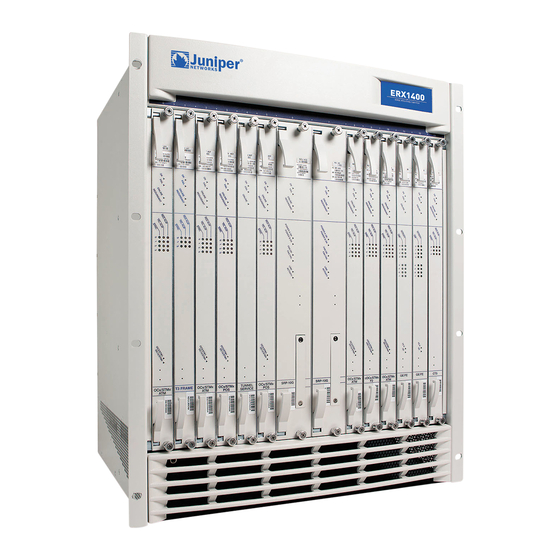
In this model, all line modules operate at full wire speed simultaneously. The ERX-1410 system manages high levels of network traffic, and uses the 10-Gbps SRP module (SRP-10G). You can configure the ERX-1410 system to enable the line modules either to operate at full line rate performance or to allow line modules to operate at a rate dependent on the resources available. -
Page 23: The Erx System
The ERX System ERX Edge Routers Figure 1-1 ERX-1400 series front view... -
Page 24: Erx-700 Series
CHAPTER 1 ERX System Overview Figure 1-2 ERX-1400 series rear view ERX-700 Series In the ERX documentation, the term ERX-700 series refers to both the ERX-705 system and the ERX-700 system. The terms ERX-705 system and ERX-700 system refer to the specific models. The ERX-705 system is a compact, high-performance model that manages low traffic density and uses a 5-Gbps SRP module, the SRP-5G+ module. - Page 25 The ERX System ERX Edge Routers The ERX-705 chassis is the same as the ERX-700 chassis (see Figure 1-3 Figure 1-4). The chassis contains seven slots to accommodate modules. Installation procedures and operating procedures are identical for both systems. All ERX systems use the same SRP I/O modules. Note: The system may look different from the systems shown in the figures in this chapter, depending on the line modules in the slots.
-
Page 26: Where The Erx System Fits In
CHAPTER 1 ERX System Overview Where the ERX System Fits In Figure 1-5 router in an end-to-end Internet network. Communications with the system can take place over a variety of media. In customers are businesses using T1/T3 communication lines. In Figure DSL access multiplexer (DSLAM). -
Page 27: Erx System Modules
ERX System Modules ERX Edge Routers ERX System Modules The system supports an SRP module and a selection of line modules. You can use any line module for access or uplink. Access line modules receive traffic from low-speed circuits, and the system routes the traffic onto higher-speed uplink line modules and then to the core of the Internet. -
Page 28: Srp Module
CHAPTER 1 ERX System Overview SRP Module The SRP module (see connect to the system’s midplane and to each other: • • An SRP module must be present for the system to boot. For details about installing SRP modules, see specifications of SRP modules, see Caution: Do not remove the SRP module while the system is running. -
Page 29: Srp I/O Module
Figure 1-8 SRP module SRP I/O Module A single corresponding input/output module called the SRP I/O module interfaces with one or two SRP modules through the system’s midplane. The same SRP I/O works with all models of the SRP module. This I/O module is two slots wide. -
Page 30: Line Modules
1-10 CHAPTER 1 ERX System Overview Line Modules Line modules process data from different types of network connections. For information about the available line modules and which SRP modules support specific line modules, see Specifications. Figure 1-9 line modules, see Packet Classification Each line module supports packet classification on ingress. -
Page 31: I/O Modules
I/O Modules Most line modules have a corresponding input/output (I/O) module that provides the physical interconnection to the network. Insert each I/O module in the back of the system, directly behind its corresponding line module. For information about which line modules pair with which I/O modules, see installing I/O modules, see Network Management Tools... -
Page 32: Nvs Cards
1-12 CHAPTER 1 ERX System Overview SRP I/O module located in the rear of the chassis. If the primary SRP fails, the redundant SRP module assumes control without rebooting or initializing itself. (As a consequence, if you upgrade software, you must copy the software to the redundant SRP and reboot it.) For information about configuring and managing SRP module redundancy, see System Basics Configuration Guide, Chapter 5, Managing Line Modules... -
Page 33: Line Modules
If there is not enough space on the primary NVS card to create the synchronization reserve file, the synchronize command fails, and you see a warning message on the console. To resolve this issue, either delete unwanted files from the primary NVS card or replace the redundant NVS card with a higher-capacity NVS card. -
Page 34: Power
1-14 CHAPTER 1 ERX System Overview Figure 1-10 Data flow when a spare line module is active For information about installing modules for line module redundancy, see Chapter 3, Installing ERX and managing SRP module redundancy, see Configuration Guide, Chapter 5, Managing Line Modules and SRP Modules, for more information. -
Page 35: Fans
The Next Step 1-15 ERX Edge Routers Fans Forced air-cooling keeps the temperature of the ERX modules and components within normal operating limits. In the ERX-1400 series, six cooling fans are located in a tray at the top of the system (see Figure 7-5). - Page 36 1-16 CHAPTER 1 ERX System Overview...
-
Page 37: Before You Begin
Installing the ERX System This chapter provides procedures for installing the ERX-1400 series and the ERX-700 series either as freestanding devices or in a distribution rack. Topic Before You Begin Unpacking the ERX-1400 Series Unpacking the ERX-700 Series Freestanding Installation Rack-Mounted Installation The Next Step Before You Begin... - Page 38 CHAPTER 2 Installing the ERX System Figure 2-1 Packaged ERX-1400 series To unpack the ERX-1400 series: Cut the two straps that secure the carton to the skid. See Open the carton from the top. Remove the box of accessories that sits on top of the router. Unlock the four plastic clips that hold the box to the skid by squeezing them in their center and pulling out.
-
Page 39: Unpacking The Erx-1400 Series
Figure 2-2 Lifting the carton off an ERX-1400 series Use a Phillips screwdriver to remove the three screws (10-32 x 3/8 in) that attach each of the two L-brackets to the router. To move the router more easily from the skid, unscrew one of the L-brackets from the skid by removing the three screws that attach it to the skid. -
Page 40: Unpacking The Erx-700 Series
CHAPTER 2 Installing the ERX System Figure 2-3 Removing an L-bracket Unpacking the ERX-700 Series The ERX-700 series come boxed but not attached to a skid. For your convenience, we recommend that you unpack the ERX system in the location where you want to install it. To unpack the ERX-700 series: Depending on where you want to position the system, proceed to Freestanding Installation... -
Page 41: Freestanding Installation
Freestanding Installation This section provides instructions for installing the system on a table top or in any other freestanding mode. See for information about site requirements. Figure 2-4 ERX-1400 series front view Warning: Two people are required to lift an ERX system. The system is extremely heavy. -
Page 42: Rack-Mounted Installation
ERX-700 series system and the ERX-1400 series system so that the air can circulate between the systems. See available from Juniper Networks. If you install an ERX-1400 series system above an ERX-700 series system, there is no need to install a plenum between the units because the ERX-1400 series system has one at its base. -
Page 43: Safety Guidelines
Safety Guidelines Observe the following safety guidelines when mounting the system in a rack. Rack Installation Warning: Install equipment in the rack from the bottom upward. This will maintain the stability of the rack and reduce the chance of the rack’s tipping over. - Page 44 Connect the necessary cables (see System, for instructions on installing the cables). illustrates a distribution rack with one ERX-1410 system and Chapter 4, Cabling the ERX...
- Page 45 Rack-Mounted Installation ERX Edge Routers Figure 2-6 Rack with ERX-700 systems and an ERX-1410 system...
-
Page 46: The Next Step
2-10 CHAPTER 2 Installing the ERX System The Next Step After you finish installing the system: • • If the system was delivered with the modules already installed, go to Chapter 4, Cabling the ERX System, for instructions on connecting cables. -
Page 47: Installing Erx Modules
Installing ERX Modules This chapter describes how to physically install and remove ERX modules. If the modules you want are already installed in the system, you can skip this chapter and go to For information about managing installed modules, see Basics Configuration Guide, Chapter 5, Managing Line Modules and Topic Overview... -
Page 48: Slot Groups
There are no slot groups in the ERX-1440 system. Slot Groups for the ERX-1410 System A slot group in the ERX-1410 system comprises three adjacent chassis slots. The groups for the ERX-1410 system consist of the following slots (Figure • •... -
Page 49: Slot Groups For The Erx-700 Series
Slots 6 and 7 are reserved for the SRP modules. Figure 3-2 ERX-1400 slot groups Slot Groups for the ERX-700 Series A slot group in the ERX-700 series comprises one slot or two adjacent slots. The groups for the ERX-700 series consist of the following slots (Figure 3-3): •... -
Page 50: Combinations Of Line Modules
CHAPTER 3 Installing ERX Modules Figure 3-3 ERX-700 series slot groups Combinations of Line Modules For information about allowed combinations of line modules, see System Basics Configuration Guide, Chapter 5, Managing Line Modules and SRP Replacing and Managing Modules For information about software procedures associated with replacing and managing modules, see Chapter 5, Managing Line Modules and SRP Hot-Swapping Modules... -
Page 51: Order Of Installation
Protecting Modules and Slots ERX Edge Routers On the ERX-1400 series, the grounding jacks are inside the front bezel in the lower-left area of the front of the chassis (Figure 3-4) and in the upper-right corner on the rear of the chassis. On the ERX-700 series, the grounding jack is in the lower-right corner on the rear of the chassis. -
Page 52: Safety Guidelines
Repair Warning: Never attempt to repair parts of modules yourself. Only trained customer service personnel are authorized to service parts. Call Juniper Networks Customer Service to make arrangements to return defective modules for repair. Installing SRP I/O and SRP Modules You should install SRP modules only in chassis slots 6 and 7 of the ERX-1400 series and slots 0 and 1 of the ERX-700 series. - Page 53 Figure 3-5 Removing the blank faceplate Caution: Always handle the module by its edges. Do not touch the components, pins, leads, or solder connections. Remove the SRP I/O module from its antistatic bag. Position the module as follows: • For the ERX-1400 series, position the module vertically so that the labeling is upright.
-
Page 54: Installing An Srp Module
CHAPTER 3 Installing ERX Modules Figure 3-6 Installing an SRP I/O module in the ERX-1400 series Installing an SRP Module To install an SRP module: Caution: When handling modules, use an antistatic wrist strap connected to the ERX system’s ESD grounding jack. This action helps to protect the module from damage by electrostatic discharge. - Page 55 Caution: Always handle the module by its edges. Do not touch the components, pins, leads, or solder connections. Remove the SRP module from its antistatic bag. Make sure that the ejectors are in position 1, as shown in Figure 3-7 Positioning the ejectors Position the module as follows: •...
-
Page 56: Installing Line Modules And Their I/O Modules
3-10 CHAPTER 3 Installing ERX Modules Figure 3-8 Installing an SRP module Installing Line Modules and Their I/O Modules This section describes the procedures for installing line and I/O modules. Note: Install the I/O module before you install the corresponding line module; otherwise, the ERX system diagnostics fail, and after the line module has tried to reboot, its status will be “inactive”... -
Page 57: Installing A Line Or I/O Module
Installing a Line or I/O Module To install a module: Connect the antistatic wrist strap to the ESD grounding jack on your ERX system. Caution: When handling modules, use an antistatic wrist strap connected to the ERX system’s ESD grounding jack. This action helps to protect the module from damage by electrostatic discharge. - Page 58 3-12 CHAPTER 3 Installing ERX Modules Figure 3-9 Installing a module in the ERX-1400 series Insert the module into the midplane by simultaneously depressing both ejectors (as shown in Figure on the module. Tighten the module’s captive screws using a Phillips screwdriver. Turn both screws several times before tightening them completely to allow the module to sit correctly.
-
Page 59: Removing A Module
Removing a Module To remove a module: Caution: If you do not use the halt command before removing or powering down an SRP, the system’s NVS card may become corrupted. Enter the halt command. Line Modules and SRP Modules command. Caution: When handling modules, use an antistatic wrist strap connected to the ERX system’s ESD grounding jack. -
Page 60: Installing Components For Line Module Redundancy
3-14 CHAPTER 3 Installing ERX Modules Figure 3-10 Installing the blank faceplate If you remove an I/O module and not the corresponding line module, the line module reboots, and then its status will be “inactive” when you issue a show version command. If you remove a line module and do not delete the corresponding configuration, the status of the line module will be “not present”... -
Page 61: Installing The Line Modules
Caution: When handling modules, use an antistatic wrist strap connected to the ERX system’s ESD grounding jack, and hold modules by their edges. Do not touch the components, pins, leads, or solder connections. These actions help to protect modules from damage by electrostatic discharge. Installing the Line Modules To install the line modules in a redundancy group: Install the spare line module in the lowest-numbered slot of the... -
Page 62: Installing The I/O Modules
3-16 CHAPTER 3 Installing ERX Modules Figure 3-11 Installing a redundancy midplane Installing the I/O Modules To install the I/O modules in a redundancy group: Caution: When setting up a redundancy group with line modules, be sure to install the redundancy I/O module in the lowest-numbered slot of the redundancy group. It is possible to install the redundancy I/O module in other slots;... -
Page 63: Verifying The Installation
Verifying the Installation To verify that the installation is complete: Turn on the power switches. The system will reboot. Issue the show redundancy command, and verify that the display shows the redundancy hardware. The Next Step After you have installed the modules and are confident that they sit correctly in their respective chassis slots, you are ready to connect cables. - Page 64 3-18 CHAPTER 3 Installing ERX Modules...
-
Page 65: Cabling The Erx System
Cabling the ERX System This chapter describes how to cable the ERX system. Before you cable the system, ensure that you have completed all installation instructions identified in previous chapters. Topic Before You Begin Cabling Your ERX System Safety Guidelines Cabling the Power Input Module Cabling the SRP I/O Module Cabling I/O Modules... -
Page 66: Cabling Your Erx System
CHAPTER 4 Cabling the ERX System Cabling Your ERX System Cabling the system takes only a few minutes. You need these items: • • • • • We recommend that you use shielded cables where appropriate and perform the cabling tasks in this order: A 1/8"... -
Page 67: Safety Guidelines
Safety Guidelines ERX Edge Routers Figure 4-1 Cabling your ERX system Safety Guidelines Observe the following guidelines when cabling your ERX system. Ground (Earth) Warning: Connect either the freestanding ERX system or the rack to ground (earth), and ensure that a reliable grounding path is maintained in the rack. -
Page 68: Cabling The Power Input Module
CHAPTER 4 Cabling the ERX System Lightning Activity Warning: Do not work on the system or connect or disconnect cables during lightning activity. DC Power Disconnection Warning: Before powering on the ERX system, remove power from the DC circuit by deactivating the circuit breaker on the panel board that services the DC circuit. - Page 69 Follow the procedure in this section to connect power cables to the system. Refer to Figure 4-2 as needed. Caution: Before you begin this procedure, ensure that both Power A and Power B switches are in the OFF position. Loosen the four screws from the clear power input module cover. Remove the cover by sliding it upward so that the screw heads line up with the holes in the cover.
- Page 70 CHAPTER 4 Cabling the ERX System Figure 4-2 Power input module...
-
Page 71: Cabling The Srp I/O Module
Cabling the SRP I/O Module The next step in cabling the system is to connect cables to your SRP I/O module. See Note: The alarm function on the SRP I/O module is currently not implemented. Cable connections to your SRP I/O module are divided into two sections: external timing ports and console ports. - Page 72 CHAPTER 4 Cabling the ERX System Figure 4-3 SRP I/O module...
-
Page 73: Console Ports
To connect the clock source input ports: Depending on the connector type, complete one of the following tasks: • • Note: You can use a wire-wrap gun to attach wires to pins. Attach the opposite end of the External Timing cable or wires into your network’s clock source A. -
Page 74: Cabling I/O Modules
4-10 CHAPTER 4 Cabling the ERX System Cabling I/O Modules The following sections describe how to cable I/O modules with different types of connectors. For information about the connectors on the different line modules, see Cabling BNC Connectors To cable I/O modules with BNC connectors: Figure 4-4 I/O module with BNCs Cabling HSSI The HSSI I/O module uses a standard 50-pin HSSI connector. -
Page 75: Cabling Rj-45 Connectors
To cable I/O modules with HSSI connectors: Insert the HSSI connector into the selected port. Terminate the other end in the appropriate network connection. Repeat steps 1 and 2 for the other ports. Figure 4-5 HSSI I/O module with 50-pin HSSI connector Cabling RJ-45 Connectors To cable I/O modules with RJ-45 connectors: Insert the RJ-45 connector into the selected port. -
Page 76: Cabling Rj-48C Connectors
4-12 CHAPTER 4 Cabling the ERX System Figure 4-6 I/O module with RJ-45 connector Cabling RJ-48C Connectors To cable I/O modules with RJ-48C connectors: Figure 4-7 I/O module with RJ-48C connectors Insert the RJ-48C connector into the selected port. Terminate the other end in the appropriate network interface, such as a multiplexer (MUX) device. -
Page 77: Cabling Lc Duplex Connectors
Cabling LC Duplex Connectors In accordance with Equipment Class, Requirements, and User’s Guide I/O modules with LC connectors are defined as follows: CLASS 1 LED PRODUCT. In accordance with Equipment Class, Requirements, and User’s Guide I/O modules with LC connectors are defined as follows: CLASS 1 LASER PRODUCT. -
Page 78: Cabling Sc Duplex Connectors
4-14 CHAPTER 4 Cabling the ERX System Figure 4-8 I/O module with LC full duplex connectors Cabling SC Duplex Connectors In accordance with Equipment Class, Requirements, and User’s Guide I/O modules with SC connectors are defined as follows: CLASS 1 LED PRODUCT. In accordance with Equipment Class, Requirements, and User’s Guide I/O modules with SC connectors are defined as follows:... -
Page 79: Cabling Smb Connectors
Warning: IEC 825, Class 1 laser fiber connectors are for connection only to Class 1 laser devices. Insert the TX male fiber connector into the selected port. Terminate the other end in the appropriate network connection. Repeat steps 1 and 2 for the RX fiber connector. Repeat steps 1–3 for the remaining ports. -
Page 80: Cabling X.21/V.35 Connectors
4-16 CHAPTER 4 Cabling the ERX System Figure 4-10 I/O module with SMB connectors Cabling X.21/V.35 Connectors Four cables are available for the X.21/V.35 I/O modules: • • • • Each 200-pin proprietary socket on the I/O module provides connections to 8 V.35 or X.21 ports. -
Page 81: Cabling Redundant Ports
Figure 4-11 X.21/V.35 module with 50-pin X.21/V.35 connector Cabling Redundant Ports Some modules have redundant ports. See Specifications path to the ERX module. Caution: For port redundancy to operate correctly on a GE I/O module that supports SFPs, both the primary and redundant ports on an ERX GE I/O module must use the same type of SFP. - Page 82 4-18 CHAPTER 4 Cabling the ERX System...
-
Page 83: Chapter 5 Accessing The Erx System
Accessing the ERX System This chapter provides information on the various ways you can access the system to manage it. Managing your router includes both configuring and monitoring it. For basic information on the management of the system, see Managing the Topic Setting Up Management Access Console Port Setup... -
Page 84: Console Port Setup
CHAPTER 5 Accessing the ERX System For initial access to the system, you need to physically connect your console directly to the system’s RS-232 port. This connection allows you to use the CLI to set an IP address on the system. Once you configure the IP address, you can access the system remotely (for example, via Telnet). -
Page 85: Connecting Directly To The Erx System
Connecting Directly to the ERX System When you connect a console directly to the system, use a cable appropriate for your terminal connector. The cable must have a female DB-9 connector to attach to the RS-232 port on the system. To connect a console directly to the system: Connect the female DB-9 connector to the RS-232 port on the system’s SRP I/O module. -
Page 86: Telnet Setup
CHAPTER 5 Accessing the ERX System address for the system. The system powers up in User Exec mode. To assign an IP address: After you have assigned an IP address to the system, you can communicate remotely by running Telnet over an Ethernet network. See the next section, Telnet Setup When you have configured an IP address for the system, you can run... - Page 87 The system is now in Privileged Exec mode. Enter the configure command. host1#configure terminal Enter configuration commands, one per line. End with CNTL/Z. host1(config)# The system is now in Global Configuration mode. Enter the line command. host1(config)#line vty 0 4 host1(config-line)# The system is now in Line Configuration mode.
-
Page 88: Snmp
CHAPTER 5 Accessing the ERX System Caution: Do not change the IP address for the Ethernet interface that you are using to communicate with the system. If you change the address, you will lose the Telnet session. SNMP The system supports Simple Network Management Protocol (SNMP), a standard management protocol for IP networks. -
Page 89: Chapter 6 Powering Up The System
Powering Up the System This chapter provides instructions for powering up the system and information on electrical specifications. Topic Before You Power Up the System Powering Up Status LEDs Powering Down The Next Step Before You Power Up the System Before powering up the system, you should complete the tasks shown in Table about these tasks. -
Page 90: Powering Up
CHAPTER 6 Powering Up the System Table 6-1 Installation tasks (continued) Installation Task Connect DC power (–48 VDC) to the power input lugs on the power input module. Connect a management console to the system. (Optional) Connect the 10/100Base-T port to the network. Powering Up This procedure assumes that the system is already connected to a DC power source. -
Page 91: Initialization Sequence
Figure 6-1 ERX-1400 series power switches Initialization Sequence Each ERX line module is initialized independently. As a result, the CLI on the SRP module may become available before the line modules have completed initialization. Commands relating to a line module may fail if the module has not completed initialization. -
Page 92: The Next Step
CHAPTER 6 Powering Up the System The Next Step If you have problems powering up the system, go to Troubleshooting, for help. Chapter 8,... -
Page 93: Required Tools And Items
Maintaining the ERX System This chapter describes the procedures that you must complete to maintain the ERX system and its components. Other maintenance procedures must be performed by an authorized Juniper Networks technician. Topic Required Tools and Items Storing Modules and Components... -
Page 94: Storing Modules And Components
CHAPTER 7 Maintaining the ERX System Storing Modules and Components Caution: Failure to store electronic modules and components correctly may lead to damage of these items. Retain the packaging in which a module or component was shipped, and use this packaging to store the item. Modules are shipped in antistatic bags and protective packaging. -
Page 95: Upgrading A System That Contains Two Srp Modules
Warning: Do not insert any metal object, such as a screwdriver, or place your hand into an open slot or the backplane when the ERX system is on. Remove jewelry (including rings, necklaces, and watches) before working on equipment that is connected to power lines. -
Page 96: Replacing An Nvs Card
CHAPTER 7 Maintaining the ERX System Replacing an NVS Card To replace an NVS card on an SRP module: When this SRP module is available, synchronize the SRP modules. host1#synchronize When the SRP modules are synchronized, reboot the SRP module that you upgraded. -
Page 97: Replacing Sfps On Ge I/O Modules
Figure 7-1 NVS card slot on SRP module Remove the NVS card and place it in the antistatic container. Insert the higher-capacity NVS card into the slot. Push the higher-capacity NVS card as far as you can in the slot. When you push the card far enough, it will click into place. -
Page 98: Removing Sfps
CHAPTER 7 Maintaining the ERX System Removing SFPs To remove the SFPs: Figure 7-2 Possible release mechanisms on the SFP Caution: For port redundancy to operate correctly, both the primary and redundant ports on an ERX GE I/O module must use the same type of SFP. Obtain an antistatic container for the SFPs you will remove (see Storing Modules and Components, earlier in this chapter). -
Page 99: Installing Sfps
Installing SFPs To install SFPs: Put the antistatic wrist strap on your wrist, and connect the strap to the ESD grounding jack on your system. Identify the following items on the SFP (see • • Figure 7-3 Example of SFP Caution: Be sure to position the SFP correctly before you install it. -
Page 100: Verifying The Installation
CHAPTER 7 Maintaining the ERX System Figure 7-4 Installing an SFP on an ERX GE I/O module If you are using the redundant port on the ERX GE I/O module, repeat steps Verifying the Installation When you have replaced the SFPs and connected the cables, issue the show interface gigabitEthernet command for each interface to check that the interface is operational (up). -
Page 101: Cleaning The System
• Field descriptions › gigabitEthernet interfaceSpecifier – status of the hardware on this interface • up – hardware is operational • down – hardware is not operational › Administrative status – operational state that you configured for this interface • up – interface is enabled •... -
Page 102: Erx-1400 Series
7-10 CHAPTER 7 Maintaining the ERX System ERX-1400 Series Figure 7-5 ERX-1400 series. Figure 7-5 Location of fan tray in ERX-1400 series Figure 7-6 Fan tray in ERX-1400 series Figure 7-6 show the location of the fan tray in the... -
Page 103: Removing The Fan Tray
Removing the Fan Tray To remove the fan tray: Caution: Do not use the fan tray handle to carry the fan tray assembly. Use the handle only to pull the tray out of the chassis. Place a flathead screwdriver in the groove where the top bezel meets the chassis on the top of the system, and lever the top bezel off the front of the system. -
Page 104: Erx-700 Series
7-12 CHAPTER 7 Maintaining the ERX System ERX-700 Series Figure 7-7 Figure 7-7 Location of fan tray on the front of the ERX-700 series Removing the Fan Tray Caution: Do not use the fan tray handle to carry the fan tray assembly. Use the handle only to pull the tray out of the chassis. -
Page 105: Installing The Fan Tray
Installing the Fan Tray Caution: Do not use the fan tray handle to carry the fan tray assembly. Use the handle only to push the into the chassis. To install the fan tray: Hold the tray vertically so that the captive screws point towards you and you can read text on the labels. - Page 106 7-14 CHAPTER 7 Maintaining the ERX System...
-
Page 107: Troubleshooting
Troubleshooting This chapter explains how you can troubleshoot a specific problem at system power-up, such as abnormal LED activity or no system power. Topic Diagnosing Problems Troubleshooting Power Failures Understanding Status LEDs Monitoring Temperatures of Modules Resetting Line Modules and SRP Modules Double-Bit Errors on SRP Modules Diagnosing Problems The information in this chapter can help you identify problems by... -
Page 108: Led Activity
CHAPTER 8 Troubleshooting LED Activity Module LEDs can show you the immediate status of a module and alert you to a problem with the module or one of its ports. It is helpful to familiarize yourself with LED activity so that you can easily detect and correct a module-related problem with minimal or no system downtime. -
Page 109: Understanding Status Leds
2 Verify that system is receiving power. 3 Check whether or not the LEDs are lit. 4 Run diagnostics on SRP and line modules. 5 If system will not reset, contact Juniper Networks Customer Service. 8-4. shows the functions of the module and port status LEDs. - Page 110 CHAPTER 8 Troubleshooting Table 8-2 LED identification and activity descriptions (continued) LED Location LED Label All modules REDUNDANT Redundancy POWER A POWER B SRP module FAN OK FAN FAIL LINK ACTIVITY Ethernet line LINK modules ACTIVITY SYNC HSSI line module YEL ALM RED ALM LED Indicator LED Color OFF to ON...
- Page 111 Table 8-2 LED identification and activity descriptions (continued) LED Location LED Label LED Indicator LED Color OFF to ON ACTIVE Port status X.21/V.35 line LOOPBK Port status module ERROR Port status V.35 Port status X.21 Port status Port status Port status SYNC Port status Other line...
- Page 112 CHAPTER 8 Troubleshooting Figure 8-1 SRP module LEDs Note: The primary SRP illuminates the REDUNDANT LED only when the SRP detects that there is a secondary or standby SRP module online. The standby SRP monitors an activity signal from the primary SRP module to determine its state; it does not shadow the operations of the primary SRP.
-
Page 113: Led Activity During Booting
Understanding Status LEDs ERX Edge Routers Figure 8-2 FE2 module LEDs Figure 8-3 E3 and T3 module LEDs LED Activity During Booting When the system boots, it runs diagnostic tests, and the module status LEDs display various configurations. Observe the scenario presented in Table 8-3 to verify that the system has booted properly. -
Page 114: Abnormal Led Activity
3 If you replaced the line module or if there was a hardware failure, the system should automatically reset the module. 4 If condition persists, contact Juniper Networks Customer Service. Fan is not working Contact Juniper Networks Customer Service; the system properly or has slowed must be serviced. -
Page 115: Redundancy Status
1 Check that Ethernet cables are properly connected to both the Ethernet port and the appropriate network device. 2 Contact Juniper Networks Customer Service. 1 Check that all cables are firmly plugged into OC3 ports and the attached network device. -
Page 116: Monitoring Temperatures Of Modules
8-10 CHAPTER 8 Troubleshooting Table 8-5 Redundancy status of a line module ONLINE LED Monitoring Temperatures of Modules You can view the temperature of each module by issuing the show environment all and show environment table commands. In addition, the system generates detailed log messages if the temperature of a module is outside normal operating limits. -
Page 117: Resetting Line Modules And Srp Modules
Resetting Line Modules and SRP Modules Two recessed buttons on line modules and SRP modules provide the mechanisms for resetting. You can use the NMI button to reset the software on the module and the board reset button to reset the module. Figure 1-8 If a line module fails to respond for an extended period of time, there may be a software problem with that module. -
Page 118: Fixing Double-Bit Errors
FAIL LED on the SRP module stays on during rebooting, the SDRAM is permanently damaged and needs replacing. In this event, call Juniper Networks Customer Service to arrange for repair. Remove the second SRP module, if there is one. -
Page 119: System Specifications
System Specifications Table A-1 ERX specifications Weight Chassis only Chassis fully configured Dimensions Environmental Requirements Ambient operating temperature Ambient operating humidity Ambient storage temperature Ambient storage humidity Heat Dissipation Space Requirements ERX-1400 Series 42 lb (18.9 kg) 88 lb (39.6 kg) 22.75 (H) x 19 (W) x 16 (D) inches (57.78 x 48.26 x 40.64 cm) (NEBS GR-63-CORE compliant) - Page 120 APPENDIX A System Specifications Table A-1 ERX specifications (continued) Airflow DC Input Voltage Current Power Redundancy (input power) NEBS Certification Safety Agency Certification Electromagnetic Emissions Agency Certification ERX-1400 Series • An integral air plenum directs system’s exhaust air below the system and out the back.
- Page 121 Table A-1 ERX specifications (continued) Telecommunications Certification a.If the voltage rises above -40 VDC, the system will power off. The system will not power on again until the input voltage reaches -43 +/- 0.5 VDC. ERX-1400 Series • ACA TS 016-1997 •...
- Page 122 APPENDIX A System Specifications...
-
Page 123: Module Specifications
DS3, DS1, E1, and DS0 (single mode and multimode) provides a description of the module assemblies Type Non-ASIC ASIC Page SRP Module Model Compatibility Compatibility ERX-700 series SRP-5G ERX-1410 system SRP-5G+ SRP-10G ERX-700 series SRP-5G+ ERX-1400 series SRP-10G SRP-40G SRP-40G+... - Page 124 Non-ASIC ASIC ASIC SRP Module Model Compatibility Compatibility ERX-700 series SRP-5G+ ERX-1400 series SRP-10G SRP-40G SRP-40G+ ERX-700 series SRP-5G ERX-1410 system SRP-5G+ SRP-10G ERX-700 series SRP-5G ERX-1410 system SRP-5G+ SRP-10G ERX-700 series SRP-5G+ ERX-1400 series SRP-10G SRP-40G SRP-40G+ ERX-700 series...
- Page 125 Switch route processor (5 Gbps) SRP-10G Switch route processor (10 Gbps) Module Assemblies and Model Compatibility Type Model Compatibility Non-ASIC ERX-700 series ERX-1410 system ASIC ERX-700 series ERX-1400 series Non-ASIC ERX-700 series ERX-1410 system ASIC ERX-700 series ERX-1400 series ASIC...
-
Page 126: Performance Specifications
Capability HDLC Framing OC3/STM1 T1, E1 HDLC Framing SRP Module Model Compatibility Compatibility ERX-1440 system SRP-40G SRP-40G+ ERX-700 series SRP-5G ERX-1410 system SRP-5G+ SRP-10G ERX-700 series SRP-5G ERX-1410 system SRP-5G+ SRP-10G ERX-700 series SRP-5G+ ERX-1400 series SRP-10G SRP-40G SRP-40G+... - Page 127 Table B-2 Performance specifications for module assemblies (continued) Name Capability cOC12/STM4 F0 OC12/STM4 (single mode and multimode, OC3/STM1 multimode with and without SONET APS redundancy) T1, E1 HDLC Framing DS1, DS0 HDLC Framing DS3, DS1, DS0 HDLC Framing CT3 12 F0 DS3, DS1, DS0 HDLC Framing E3 ATM...
- Page 128 APPENDIX B Module Specifications Table B-2 Performance specifications for module assemblies (continued) Name OC3/STM1 POS (single mode and multimode)) OC12/STM4 ATM (single mode and multimode) OC12/STM4 POS (single mode and multimode) SRP-5G (5 Gbps) SRP-5G+ (5 Gbps) SRP-10G (10 Gbps) SRP-40G (40 Gbps) SRP-40G+ (40 Gbps) T3 ATM...
-
Page 129: Connection Information
Connection Information Table B-3 can combine to form the different module assemblies. This table also provides cabling specifications for the I/O modules. Table B-3 Connection information for module assemblies Assembly Line Name and Module I/O Module Capability Label Label FULL cOC3/STM1 cOCx/STMx cOC3... - Page 130 APPENDIX B Module Specifications Table B-3 Connection information for module assemblies (continued) Assembly Line Name and Module I/O Module Capability Label Label cOC3/STM1 cOCx/STMx cOC3 single mode STM1 long reach F0 I/O LONG HAUL cOC12/STM4 cOCx/STMx cOC12 STM4 multimode F0 I/O without SONET APS MULTI...
- Page 131 Table B-3 Connection information for module assemblies (continued) Assembly Line Name and Module I/O Module Capability Label Label cOC12/STM4 cOCx/STMx cOC12 single mode STM4 intermediate F0 I/O reach SINGLE MODE cOC12/STM4 cOCx/STMx cOC12 STM4 single mode F0 I/O long reach LONG HAUL FULL...
- Page 132 B-10 APPENDIX B Module Specifications Table B-3 Connection information for module assemblies (continued) Assembly Line Name and Module Capability Label CT3 12 F0 CT3/T3-F0 E3 ATM E3 ATM E3 FRAME E3 FRAME (3 ports) I/O Module No. of Label Ports Connector Type CT3/T3 75 ohm...
- Page 133 Table B-3 Connection information for module assemblies (continued) Assembly Line Name and Module I/O Module Capability Label Label E3 FRAME COCX-F3 E3-12 (12 ports) FRAME FE-2 FE-2 FE-2 FE-8 GE/FE FE-8 GE/FE 1000 Base-SX No. of Ports Connector Type BT43 SMB (cable that adapts to 75-ohm BNC is available)
- Page 134 B-12 APPENDIX B Module Specifications Table B-3 Connection information for module assemblies (continued) Assembly Line Name and Module Capability Label GE/FE 1000 Base-LH GE/FE 1000 Base-ZX GE/FE multimode I/O Module No. of Label Ports Connector Type 1 active LC full duplex 1 redundant 1 active LC full duplex...
- Page 135 Table B-3 Connection information for module assemblies (continued) Assembly Line Name and Module I/O Module Capability Label Label GE/FE single mode SINGLE MODE HSSI HSSI-3F HSSI-3 IPSec Service IPSEC No I/O SERVICE module OC3 (dual port) multimode MULTI MODE OC3 (dual port) single mode SINGLE...
- Page 136 B-14 APPENDIX B Module Specifications Table B-3 Connection information for module assemblies (continued) Assembly Line Name and Module Capability Label OC3/STM1 OCx/STMx multimode OC3/STM1 OCx/STMx single mode, intermediate reach OC3/STM1 OCx/STMx single mode, long reach I/O Module No. of Label Ports Connector Type OC3-4...
- Page 137 Table B-3 Connection information for module assemblies (continued) Assembly Line Name and Module I/O Module Capability Label Label OC3/STM1 OCx/STMx OC3-4 multimode MULTI MODE OC3/STM1 OCx/STMx OC3-4 single mode, SINGLE intermediate MODE reach OC3/STM1 OCx/STMx OC3-4 single mode, LONG long reach HAUL No.
- Page 138 B-16 APPENDIX B Module Specifications Table B-3 Connection information for module assemblies (continued) Assembly Line Name and Module Capability Label OC12/STM4 OCx/STMx multimode without SONET APS redundancy OC12/STM4 OCx/STMx multimode with SONET redundancy OC12/STM4 OCx/STMx single mode, intermediate reach without SONET APS redundancy I/O Module...
- Page 139 Table B-3 Connection information for module assemblies (continued) Assembly Line Name and Module I/O Module Capability Label Label OC12/STM4 OCx/STMx OC12 STM4 single mode, intermediate SINGLE reach with MODE SONET APS redundancy OC12/STM4 OCx/STMx OC12 STM4 single mode, long reach LONG HAUL OC12/STM4...
- Page 140 B-18 APPENDIX B Module Specifications Table B-3 Connection information for module assemblies (continued) Assembly Line Name and Module Capability Label OC12/STM4 OCx/STMx multimode with SONET redundancy OC12/STM4 OCx/STMx single mode, intermediate reach without SONET APS redundancy OC12/STM4 OCx/STMx single mode, intermediate reach with SONET APS...
- Page 141 Table B-3 Connection information for module assemblies (continued) Assembly Line Name and Module I/O Module Capability Label Label SRP-5G SRP I/O (5 Gbps) SRP (5 Gbps) SRP-5G+ SRP I/O SRP-10G SRP I/O (10 Gbps) SRP-40G SRP I/O (40 Gbps) SRP-40G+ SRP I/O (40 Gbps) No.
- Page 142 B-20 APPENDIX B Module Specifications Table B-3 Connection information for module assemblies (continued) Assembly Line Name and Module Capability Label T3 ATM T3 ATM (3 ports) T3 FRAME T3 FRAME (3 ports) T3 FRAME COCX-F3 (12 ports) TUNNEL SERVICE I/O Module No.
-
Page 143: Cable Lengths For X.21/V.35 Cables
Table B-3 Connection information for module assemblies (continued) Assembly Line Name and Module I/O Module Capability Label Label X.21/V.35 X.21/V.35 X.21/V.35 a.The GE SFP I/O module uses a range of simple form factor pluggable transceivers (SFPs) to support different modes and cable lengths. b.Assembly is superseded by a newer assembly;... - Page 144 B-22 APPENDIX B Module Specifications...
-
Page 145: Cable Pinouts
Cable Pinouts This appendix lists the cables and connector pinout assignments for the cables used with the ERX-700 series and ERX-1400 series. Topic SRP I/O Module CT1 and CE1 I/O Modules SRP I/O Module The SRP I/O module provides two management ports. You can connect a console directly to the RS-232 serial port using a shielded straight-through cable with a female DB-9 connector on one end and a male DB-25 with a crossover adapter on the DB-25 end. - Page 146 APPENDIX C Cable Pinouts Figure C-1 SRP I/O module serial port Table C-2 Table C-1 SRP I/O module – RS-232 serial connector pinout Once you have configured an IP address on the system, you can connect a console running Telnet to the 10/100Base-T Ethernet port on the SRP I/O module.
- Page 147 Figure C-2 SRP I/O module Ethernet port Table C-2 lists the pinout for the Ethernet cable’s RJ-45 connector. Table C-2 SRP I/O module – RJ-45 connector pinout Signal TX + TX – RX + RX – To facilitate connecting the system to a terminal, the system is shipped with one of each of the following cable adapters: •...
-
Page 148: Ct1 And Ce1 I/O Modules
APPENDIX C Cable Pinouts Table C-3 Table C-3 DB-9 – RJ-45 crossover adapter pinout DB-9 Pin Table C-4 Table C-4 DB-9 – RJ-45 straight-through adapter pinout DB-9 Pin CT1 and CE1 I/O Modules CT1 I/O modules have 24 RJ-48C female connectors. CE1 I/O modules have either 20 RJ-48C female connectors or two 25-pair female Telco connectors. - Page 149 Figure C-3 CT1 I/O module ports Table C-5 lists the pinout for the CT1/CE1 connector. Table C-5 CT1/CE1 I/O module – RJ-48C connector pinout Signal RX Ring RX Tip TX Ring TX Tip For CE1 I/O modules with Telco connectors, the other ends of the cables are attached to a balun panel that splits the signals from two Telco connectors to 20 pairs of BNC connectors.
- Page 150 APPENDIX C Cable Pinouts Figure C-4 CE1 I/O module with Telco connectors Figure C-5 balun panel. The cables from the CE1 I/O module are plugged into the two 50-pin Telco connectors on the other side of the panel. Figure C-5 Twenty-port balun panel Table C-6 Table C-6 Pinout of 50-pin Telco connector to ports 0–9 shows the location of the 20 pairs of BNC connectors on a...
- Page 151 Table C-6 Pinout of 50-pin Telco connector to ports 0–9 (continued) Signal Port 4 RX TIP Port 4 TX TIP Port 5 RX TIP Port 5 TX TIP Port 6 RX TIP Port 6 TX TIP Port 7 RX TIP Port 7 TX TIP Port 8 RX TIP Port 8 TX TIP...
- Page 152 APPENDIX C Cable Pinouts Table C-7 Pinout of 50-pin Telco connector to ports 10–19 (continued) Signal Port 17 RX TIP Port 17 TX TIP Port 18 RX TIP Port 18 TX TIP Port 19 RX TIP Port 19 TX TIP Signal Port 17 RX RING Port 17 TX RING...
-
Page 153: Preparing Your Site
Preparing Your Site This chapter provides information about preparing your site before installing the ERX system. We recommend that you consider all requirements and specifications indicated in this appendix before installing the system. Topic Your Preinstallation Responsibilities Environmental Requirements Safety Guidelines Rack Requirements Cabling Recommendations Your Preinstallation Responsibilities... -
Page 154: Environmental Requirements
APPENDIX D Preparing Your Site • Environmental Requirements Choose a location for the system that is dry, relatively dust free, well ventilated, and air conditioned. If you install equipment in a rack, be sure that the floor is capable of supporting the combined weight of the rack and the installed equipment. -
Page 155: Rack Requirements
Lightning Activity Warning: Do not work on the system or connect or disconnect cables during lightning activity. DC Power Disconnection Warning: Before powering on the ERX system, remove power from the DC circuit by deactivating the circuit breaker on the panel board that services the DC circuit. -
Page 156: Space Requirements
300 pounds (136 kilograms). The system fits in a 19-inch rack. You can install a system in a 23-inch rack if you use the 23-inch ears available from Juniper Networks. Contact your Juniper Networks sales representative for more... - Page 157 Rack Requirements ERX Edge Routers Figure D-1 Fully loaded 84-inch rack...
- Page 158 APPENDIX D Preparing Your Site Figure D-2 ERX-700 series and ERX-1400 series systems installed in 84-inch rack...
-
Page 159: Cabling Recommendations
Cabling Recommendations You may want to consult the document Equipment Building System (NEBS) Requirements: Physical Protection, Issue 1, October 1995 Comply with the following recommendations: • Use only shielded cables. • Ensure that cable distance and rate limits meet IEEE-recommended maximum speeds and distances for signaling purposes. - Page 160 APPENDIX D Preparing Your Site...
-
Page 161: Appendix E Installing Erx System Software
Software Caution: Check the Release Notes for extra information about installing and upgrading the software. This appendix provides information on how to install new software on the Juniper Networks ERX systems. Topic Overview Installing Software When a Firewall Exists Installing Software When a Firewall Does Not Exist... -
Page 162: Installing Software When A Firewall Exists
APPENDIX E Installing ERX System Software example, if the release number is x.y.z, the name of the directory is x-y-z. To identify the software release file: The procedures outlined in the following sections provide detailed instructions for typical installations. For additional information about commands and troubleshooting, refer to Configuration Guide Installing Software When a Firewall Exists... -
Page 163: Task 1: Obtain The Required Information
Install the software release file to the system space on the ERX system. Save the current configuration. Reboot the system. Task 1: Obtain the Required Information Before you install the software, obtain the following information: • The password (if one is configured) that allows you to access Privileged Exec mode on the ERX system •... -
Page 164: Task 4: Mount The Cd On The Network Host
APPENDIX E Installing ERX System Software Task 4: Mount the CD on the Network Host The way you mount the CD on the network host depends on the type of computer you use, the operating system, and the network configuration. To find out how to mount a CD on the network host, review the manual for the operating system, or check with your network administrator. -
Page 165: Task 6: Enable The Ftp Server On The Erx System
If the network host is listed, go to step 8. Otherwise, proceed with step 6. Add an entry to the Static Host Table so that the ERX system can access the network host. The host command allows you to specify the network host name and IP address. -
Page 166: Task 9: Install Files On The System Space
APPENDIX E Installing ERX System Software directory. If you specify a subdirectory that does not exist, the ERX system creates the directory. Note: Be sure to transfer the software release file and all the files it lists. Task 9: Install Files on the System Space Installing the software release file to the system space installs all files listed in the software release file. -
Page 167: Installing Software When A Firewall Does Not Exist
Press <CTRL-Z> to return to Privileged Exec mode. Check that the ERX system is ready to boot with the new software release. host1#show boot If the old software version is still listed, verify that you completed the previous steps correctly. Run the reload command. -
Page 168: Task 1: Obtain The Required Information
APPENDIX E Installing ERX System Software To install the software, perform the following tasks: Task 1: Obtain the Required Information Before you install the software, obtain the following information: • • • • • • Task 2: Access Privileged Exec Mode To access this mode via the CLI: Task 3: Configure IP on an Interface Typically, you configure IP on the Fast Ethernet interface of the SRP... -
Page 169: Task 4: Configure Access To The Network Host
Installing Software When a Firewall Does Not Exist Determine the port number of the module. Determine whether the interface already has an IP address. host1#show ip interface fastEthernet 6/0 Note: If an IP interface is not configured, you see the message: “Invalid interface.” If the interface already has an IP address, go to step 5. -
Page 170: Task 5: Mount The Cd On The Network Host
E-10 APPENDIX E Installing ERX System Software Task 5: Mount the CD on the Network Host The way you mount the CD on the network host depends on the type of network host you use, the operating system, and the way your network is configured. -
Page 171: Task 7: Save The Current Configuration
Installing Software When a Firewall Does Not Exist Task 7: Save the Current Configuration To save the current configuration, use the copy running-configuration command: host1#copy running-configuration filename.cnf Task 8: Reboot the System To reboot the system using the newly installed software: Access Global Configuration mode. -
Page 172: Installing Software In Boot Mode
E-12 APPENDIX E Installing ERX System Software Installing Software in Boot Mode To install the ERX software in Boot mode, you must access the CLI via the local console. To install the software: Task 1: Obtain the Required Information Before you install the software, obtain the following information: •... -
Page 173: Task 3: Assign An Ip Address
Installing Software When a Firewall Does Not Exist Task 3: Assign an IP Address When you assign an IP address to the ERX system in boot mode, the address is configured on the Fast Ethernet port of the primary SRP module. -
Page 174: Task 7: Reboot The System
E-14 APPENDIX E Installing ERX System Software Task 7: Reboot the System To reboot the system using the newly installed software: Copying Release Files from One ERX System to Another When you have copied the release files from a network host to one ERX system, you can transfer files from that ERX system to other ERX systems on the network. -
Page 175: Upgrading Systems That Are Operating With Two Srp Modules
To transfer release files from a source ERX system to a destination ERX system, follow the instructions in Does Not Exist, • Substitute the source ERX system for the network host. • Omit the step about mounting the CD. • Copy the file to the system space of the second ERX system from the user space of the first ERX system. - Page 176 E-16 APPENDIX E Installing ERX System Software The redundaant SRP module will automatically reboot, because the software release that it is configured to run differs from the software release it is running. Wait for the redundant SRP module to boot, initialize, and reach the standby state.
-
Page 177: Appendix F Declaration Of Conformity
Declares, that the product(s) Product Name: Model Number(s): Product Options: Conforms to the following Product Specifications: Safety: EMC: Juniper Networks, Inc. Juniper Networks, Inc. 10 Technology Park Drive Westford, Massachusetts 01886 Edge Switching Router ERX-700, ERX-1400, ERX-1440 All Modules IEC 60950-1(2001-10) Ed. 1.0 Information technology equipment - Safety -... - Page 178 APPENDIX F Declaration of Conformity Declaration of Conformity according to ISO/IEC Guide 22 and EN4514 Supplementary Information: The products herewith comply with the requirements of the (73/23/EEC), the EMC Directive (89/336/EEC), and the (1999/5/EEC), and carry the CE markings accordingly. Products were tested in a typical configuration.
-
Page 179: Index
Index Numbers 10/100BASE-T port 4-7, 4-9 access, management 1-11, 5-1 to 5-6 setting up console 5-2 to 5-4 SNMP 1-11, 5-6 Telnet setup 5-4 accessing an FTP server. See FTP access Boot mode E-12 Privileged Exec command mode E-3, E-8 software release file E-6, E-10, E-13 access line modules 1-7 ACTIVITY LED 8-4... - Page 180 Device Management System, NMC-RX 1-11 diagnosing problems. See troubleshooting diagnostic LEDs 8-3 to 8-9 dimensions of ERX system A-1 dissipation, heat A-1 distribution rack D-3 documentation set, Juniper Networks xvii CD xviii CD, using the xix comments on xix double-bit errors detecting 8-11...
- Page 181 E-3, E-8, E-12 spare line modules 3-15 installing the system software xv IP address, assigning 5-3, E-3, E-8, E-13 Juniper Networks documentation set xvii CD xviii CD, using the xix comments on xix LEDs 8-2, 8-3 to 8-9...
- Page 182 5-2 to 5-4 SNMP 1-11, 5-6 Telnet setup 5-4 Management Information Bases 1-11 managing modules 3-4 manuals, Juniper Networks xvii comments on xix on CD xviii mechanical requirements for distribution rack D-3 MIBs (Management Information Bases) 1-11...
- Page 183 source A 8-4, 8-8 source B 8-4, 8-8 specifications A-2 POWER A LED 8-4 POWER B LED 8-4 powering down ERX system 6-3 powering up ERX system 6-1 to 6-4 power input module, cabling 4-4 to 4-6 power switches 4-5 to 4-6, 6-2 preinstallation responsibilities D-1 preparing site for installation D-1 to D-7 Privileged Exec command mode E-3, E-8...
- Page 184 Index SRP modules 1-7, 1-8 to 1-9 compatibility with ERX models B-3 to B-4 compatibility with line modules and I/O modules B-1 to B-4 errors on 8-11 installing 3-8 to 3-10 LEDs on 1-7, 8-4, 8-6 models 1-2 to 1-5, B-6 PCMCIA slot 1-8 powering down 6-3 power use B-6...
Need help?
Do you have a question about the ERX-1410 and is the answer not in the manual?
Questions and answers