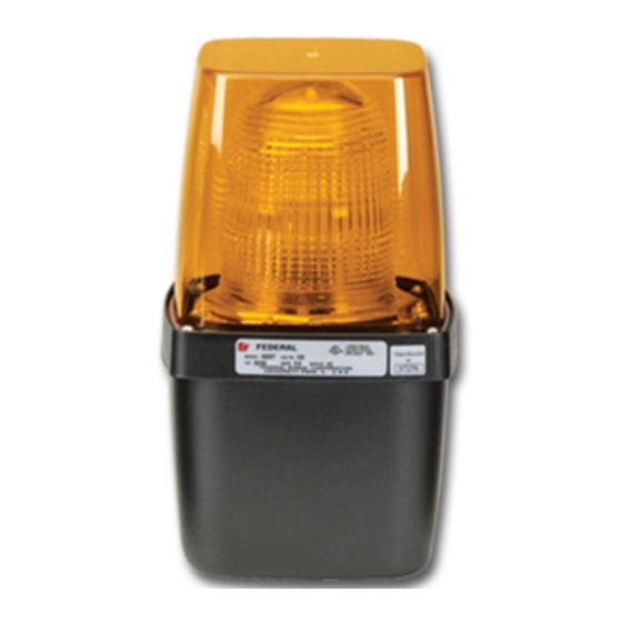
Summary of Contents for Federal Signal Corporation 400 Series
- Page 1 Model 400 Series Lights Installation Instructions 256A424G REV. A 610 Printed in U.S.A.
- Page 2 Warranty – Seller warrants all goods for five years on parts and 2-1/2 years on labor, under the following conditions and exceptions: Seller warrants that all goods of Seller's manufacture will conform to any descriptions thereof for specifications which are expressly made a part of this sales contract and at the time of sale by Seller such goods shall be commercially free from defects in material or workmanship.
-
Page 3: Table Of Contents
Figure 2 Grommet in 7/8" drilled hole in bracket ........8 Figure 3 Adapter plate attached ............9 Figure 4 Ceiling mount ............... 12 Figure 5 Strobe tube degradation ............16 Tables Table 1 Kit contents ................6 Table 2 Replacement parts ..............14 Model 400 Series Lights... - Page 4 Vibratone is a registered trademark of Federal Signal Corp. Keps is a registered trademark of ITW Shakeproof Model 400 Series Lights...
-
Page 5: Safety Messages To Installers
Note: A Model 350 Vibratone Horn can be installed in the ® lower housing of a Model 400 Series Light. It is usually more convenient to install the audible device in the light before attaching the light to the mounting surface. Therefore, it is recommended that the audible device be installed (if applicable) before proceeding. -
Page 6: Unpacking The Light
Description Hex. Head Mach. Screw, 1/4-20 Allen Head Set Screws, Cone Point 6-32 x 3/16" Hex Screws, Taptite Nut, Keps , 1/4-20 ® Cover Plate, Mounting Adapter Cover, Self-Adhesive Plate, Mounting Adapter Bracket, Wall/Ceiling Mounting Grommet Model 400 Series Lights... -
Page 7: Installation
See Figure 1. Drill a 7/8" hole in the wall/ceiling mounting bracket. Use caution to avoid damaging the bracket. Figure 1 7/8" drilled hole in bracket 7/8" DIA. HOLE DRILLED BY INSTALLER TO ACCEPT 1/2" CONDUIT CONNECTOR 1-3/16" APPROX. 7/8" APPROX. 290A1504 Model 400 Series Lights... -
Page 8: Figure 2 Grommet In 7/8" Drilled Hole In Bracket
1/4"-20 x 1/2" hex-head machine screws. Ensure that all wiring from the interior of the light passes through the large center hole in the end of the bracket. Route the wiring through the conduit fitting that was installed in step 2. Model 400 Series Lights... -
Page 9: Figure 3 Adapter Plate Attached
CUSTOMER SUPPLIED MAIN MOUNTING FRAME HOUSING 290B1505B Place the light/mounting bracket assembly over the adapter plate and tighten the two cone point set screws. Ensure that the screws engage the two dimples in the adapter plate. Model 400 Series Lights... -
Page 10: Electrical Box Mount
Install the adapter plate (supplied) on the 4" x 4" electrical box, using the appropriate user-supplied hardware. Start the two 10-32 x 3/4" cone point set screws in the threaded holes in the upper and lower edges of the wall/ ceiling mounting bracket. Model 400 Series Lights... -
Page 11: Ceiling Mount
Make sure that the screws engage the two dimples in the adapter plate. Ceiling Mount Model 400 Series Light can be mounted flat on a ceiling or on a 4" x 4" electrical box. Both of these mounting methods are variations on those methods already described. However, the wall/ceiling mounting bracket must be attached to the lower housing of the light. -
Page 12: Figure 4 Ceiling Mount
1/4-20 SCREWS HEX HD. (2) GROMMET (1) 10-32 SET HOUSING (1) SCREWS ALLEN HD. (2) 6-32 NUTS, HOUSING FASTENING (4) 1/4-20 HEX NUTS EXT. KEPS (2) COVER (1) (SELF ADHESIVE) MAIN MOUNTING FRAME LEXAN DOME (1) 290B1507B Model 400 Series Lights... - Page 13 Reassemble the light following steps 1 and 2 in reverse order. Install the light on the ceiling following the Flat Surface Mount instructions on page 7 or the Electrical Box Mount instructions on page 10. Model 400 Series Lights...
-
Page 14: Obtaining Service, Assistance, And Parts
Lamp (400R) K8107181 Interior Fresnel Lens, Clear (400ST) K8248C004-04 Tube, Strobe (400ST) K8107178 PC Board Assembly (400ST) K200D825 For instructions on how to service the Model 400ST Strobe Light, see document no. 256A470 available at: http://www.federalsignal-indust.com Model 400 Series Lights... -
Page 15: Replacing The Strobe Tube (400St)
Figure 5 on page 16, replace the tube. Not replacing the strobe tube when any of the above conditions exist could cause a breakdown of other components on the printed circuit board. Model 400 Series Lights... -
Page 16: Figure 5 Strobe Tube Degradation
Install a new strobe tube and reassemble the light. Figure 5 Strobe tube degradation A. NEW STROBE TUBE B. A USED STROBE TUBE TENDS TO DISCOLOR IN THE AREAS SHOWN AND SHOULD BE REPLACED. 290A16502 © 2010 Federal Signal Corporation Model 400 Series Lights...


Need help?
Do you have a question about the 400 Series and is the answer not in the manual?
Questions and answers