Table of Contents
Advertisement
Quick Links
These instructions are presented a in step by step sequence.
Please read it through before installation.
Note: The dimensions of the Template are shown in inches. See
attached page for the Metric Conversion Table for millimeters.
P:\INSTALLATION INST\Mechanical Hardware\INST-S6300.vsd
801 Avenida Acaso, Camarillo, Ca. 93012
• (805) 494-0622 • www.sdcsecurity.com
E-mail: service@sdcsecurity.com
Rev C
02-17
Page 1
Advertisement
Table of Contents

Related Manuals for SDC S6300 Series


Summary of Contents for SDC S6300 Series
- Page 1 801 Avenida Acaso, Camarillo, Ca. 93012 • (805) 494-0622 • www.sdcsecurity.com E-mail: service@sdcsecurity.com These instructions are presented a in step by step sequence. Please read it through before installation. Note: The dimensions of the Template are shown in inches. See attached page for the Metric Conversion Table for millimeters.
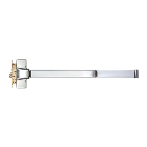
- Page 2 DESIGNATION OF PARTS End Cap Bracket Face Mortise Mortise Plate Chassis Strike End Cap Lockcase Dogging Device (Fire Exit Hardware is not equipped with this device) Chassis Cover Push Bar Chassis BEFORE INSTALLING THIS EXIT DEVICE : 1. Check device to be sure the type is correct for the application 2.
- Page 3 1. MARK DOOR FOR DEVICE AND LOCK 1/4” 31/32” 6-17/32” 8-1/32” of Mortise Lock of Device 40" to of Device Finished Floor 4-23/32” Fig 1-2 Fig 1-1 1. If door is already cut out for lock (mortised), check for proper clearance (Fig 1-1). 2.
- Page 4 3. SET LOCK HANDING A) Set the lock for proper handing to match door hand. 1) Change latch bolt handing: If the handing of the latch bolt doesn’t match door hand, remove fixing screw and pull latch bolt out from lock case. Turn complete latch bolt unit around to match door handing.
- Page 5 Check that the hub of the lock is seated in the correct position before proceeding to the next step. Insert spindle into hub of the lock case and turn until latch bolt is retracted (Fig 3-4). On the side of the lock case that is attaching to the trim, check that turning the spindle retracts the latch bolt before installing the lock...
- Page 6 5. INSTALL DEVICE: 1. Remove chassis cover from chassis assembly and end cap from end cap bracket. 2. Insert the Pull Finger beneath device chassis into the “A” hole in lock case (Fig 5-1) then mount device horizontally to the drilled position with 6 supplied screws to door (Fig 5-2). 3.
- Page 7 6. INSTALL OUTSIDE TRIM AND CYLINDER NOTE: Follow this step only if SDC’s Entry Lever trim is used. If other trim is used with this device, please refer to the original manufacturers instructions. 1. Check the direction of the outside lever to be installed, then place the reversible spring cage into ferrules with the arrow pointing in the direction of the lever rotation and fasten with screws supplied (Fig 6-1).
-
Page 8: Door Handing
7. TEST OPERATION AND INSTALL COVERS 1. Test push bar and dogging operation before installing covers: A. NO TRIM: Latch bolt is retracted by depressing push bar inside. B. WITH TRIM: Latch bolt is retracted by push bar inside, and; a) When outside key locks the lever/knob, the lever/knob will be made inoperative.
Need help?
Do you have a question about the S6300 Series and is the answer not in the manual?
Questions and answers