Advertisement
INSTALLATION INSTRUCTIONS
P:\INSTALLATION INST\Mechanical Hardware\INST-S6200.vsd
801 Avenida Acaso, Camarillo, Ca. 93012
• (805) 494-0622 • www.sdcsecurity.com
E-mail: service@sdcsecurity.com
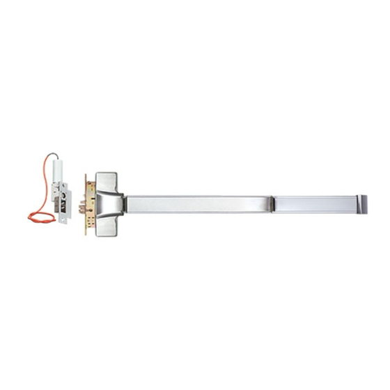
S6200 SERIES
PANIC/FIRE EXIT
SURFACE MOUNTED
VERTICAL ROD DEVICES
Rev -
01/11
These instructions are presented
in a step by step sequence.
Please read it through before
installation.
Note: The dimensions are shown
in inches. See attached page for
the Metric Conversion Table for
millimeters.
Page 1
Advertisement
Table of Contents

Subscribe to Our Youtube Channel
Related Manuals for SDC S6200 Series


Summary of Contents for SDC S6200 Series
- Page 1 801 Avenida Acaso, Camarillo, Ca. 93012 • (805) 494-0622 • www.sdcsecurity.com E-mail: service@sdcsecurity.com S6200 SERIES PANIC/FIRE EXIT SURFACE MOUNTED VERTICAL ROD DEVICES INSTALLATION INSTRUCTIONS These instructions are presented in a step by step sequence. Please read it through before installation.
- Page 2 DESIGNATION OF PARTS Top Strike Fixing Plate Top Strike (Back View) Top Strike Top Strike End Cap (Panic Label) (Fire Label) Top Latch End Cap Bracket Assembly Top Latch Assembly Cover Mechanism Mounting Housing Bracket Top Rod Dogging Device Fire Exit Rod Guide Shaft Connector Hardware is not equipped...
- Page 3 STEP 1: PREPARE DOOR 1. Mark position of holes on the door per template (see figure 1). 2. Drill all holes marked on the door for the device chassis and top and bottom latch mounting brackets. 3. Mortise hole for outside trim is required. NOTE;...
- Page 4 STEP 2: INSTALL BRACKETS, DEVICE & TRIM 1. Remove chassis cover from chassis assembly and end cap from end cap bracket. 2. Cut the length if required. For user information; This model device has three different lengths: For use on 3' wide door, device = 33" For use on 3.5' wide door, device = 40"...
- Page 5 STEP 3: INSTALL BOTTOM ROD AND BOTTOM STRIKE 1. Mount the bottom latch assembly into the mounting bracket (see figure 3). 2. Screw the threaded end of the bottom rod onto the bottom latch assembly (see figure 4). Threaded end of Bottom rod Figure 3 Figure 4...
- Page 6 STEP 4: INSTALL TOP ROD AND TOP STRIKE 1. Mount the top latch assembly into the mounting bracket (see figure 7). 2. Screw the threaded end of the top rod onto the top latch assembly completely (see figure 8). Threaded end Figure 7 of top rod Figure 8...
- Page 7 6. Mark and drill mounting holes on the jamb for the top strike per the strike template (see figure 12). Fasten the top strike to the jamb with the screws supplied (see figure 13). Figure 12 Figure 13 NOTE: Attach third screw last after strike has been properly aligned, STEP 5: TEST OPERATION 1.
-
Page 8: Door Handing
Outside of Door Door Handing Use this diagram to determine the hand of door. Inside of Door NOTE: To extend the life of this device, it is recommended to activate Dogging Wrench the dogging feature during high traffic periods of the day. Dogging: Release Dogging: Insert dogging wrench and...
Need help?
Do you have a question about the S6200 Series and is the answer not in the manual?
Questions and answers