
Subscribe to Our Youtube Channel
Related Manuals for GESTRA NRR 2-60


Summary of Contents for GESTRA NRR 2-60
- Page 1 Level Controller NRR 2-60 Original Installation & Operating Manual 819693-00 E n g l i s h...
-
Page 2: Table Of Contents
Installing the NRR 2-60 level controller ....................... 17 Electrical connection safety notes ....................... 17 Wiring diagram for NRR 2-60 level controller ..................... 18 Wiring diagram for NRR 2-60 level controller as 3-component regulator ..........19 Electrical connection ............................ 20 Bus line, cable length and cross-section ....................20 Connecting the 24V DC power supply ...................... - Page 3 Indication of system malfunctions ......................27 What to do in the event of system malfunctions..................28 Taking out of service ............................ 28 Disposal ................................ 28 Returning decontaminated devices ......................28 EU Declaration of Conformity ........................29 NRR 2-60 - Installation & Operating Manual - 819693-00...
-
Page 4: Content Of This Manual
© Copyright All rights reserved. Any misuse, particularly reproduction and dissemination to third parties, is not permit- ted. The General Terms & Conditions of GESTRA AG apply. Scope of delivery/Product package 1 x Level Controller NRR 2-60 ■ ■... -
Page 5: How To Use This Manual
How to use this Manual This Installation & Operating Manual describes the correct use of the NRR 2-60 level controller. It applies to persons who integrate this equipment in control systems, install, bring into service, operate, maintain and dispose of this equipment. Anyone carrying out the above-mentioned activities must have read this Installation &... -
Page 6: Types Of Warning
Warning of a dangerous situation that may possibly result in death or serious injury. CAUTION Warning of a situation that may result in minor or moderate injury. ATTENTION Warning of a situation that results in damage to property or the environment. NRR 2-60 - Installation & Operating Manual - 819693-00... -
Page 7: Specialist Terms/Abbreviations
This type of electrically non-conductive connection makes sure the input and output circuits are electrically isolated from each other. PI controller Controller with proportional (P) and integral (I) control. SELV Safety Extra Low Voltage NRR 2-60 - Installation & Operating Manual - 819693-00... -
Page 8: Usage For The Intended Purpose
Combinations with a URW 60 universal converter* The NRR 2-60 level controller can also be used for the above applications in combination with a URW 60 universal converter * and an external level electrode (with a current output of 4-20 mA). -
Page 9: Applicable Directives And Standards
Usage for the intended purpose Applicable directives and standards The NRR 2-60 level controller has been tested and approved for use in the scope governed by the follow- ing directives and standards: Directives: Directive 2014/35/EU Low Voltage Directive ■ ■... -
Page 10: Basic Safety Notes
Check that the system is not carrying live voltage before commencing work. ■ ■ Faulty equipment jeopardises system safety. If the NRR 2-60 level controller does not behave as described on page 25, it may be ■ ■ faulty. Perform failure analysis. -
Page 11: Function
When MIN/MAX water level alarms arise, the appropriate output contact opens. Possible combinations of functions and equipment Combining the NRR 2-60 level controller with the level electrodes and the URB 60 visual display and operating unit provides the following functions:... -
Page 12: Technical Data
Inductive loads must have interference suppression (RC combination) as per the manufacturer's ■ ■ specification Analogue output 1 x actual value output 4 - 20 mA, e.g. for an actual value display ■ ■ Max. load resistance 500 W ■ ■ NRR 2-60 - Installation & Operating Manual - 819693-00... - Page 13 ◆ ■ 2 x 1.5 mm stranded with sleeve ◆ ■ Housing attachment: Mounting clip on support rail TH 35 (to EN 60715) ■ ■ Weight Approx. 0.5 kg ■ ■ NRR 2-60 - Installation & Operating Manual - 819693-00...
-
Page 14: Name Plate/Identification Nrr 2-60
T 55°C (131°F) TÜV . WR . xx-xxx Option CH CL CanBus GESTRA AG Münchener Str. 77 xxxxxxxxxxxx 28215 Bremen GERMANY The date of production is printed on the back of the equipment. NRR 2-60 - Installation & Operating Manual - 819693-00... -
Page 15: Factory Settings
Neutral band: ± 5 % of setpoint ■ ■ Valve runtime: 40 seconds ■ ■ MIN/MAX alarm ■ ■ off delay: 3 seconds (factory set) Quality factor: 1.00 (3-component control) ■ ■ NRR 2-60 - Installation & Operating Manual - 819693-00... -
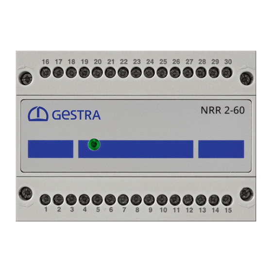
Page 16: Functional Elements And Dimensions
Fastening screws (M3) 4-pole code switch, for setting the controller Equipment settings, group and baud rate see page 23. Front membrane with status LED, see page 24 Housing Support rail TH 35 NRR 2-60 - Installation & Operating Manual - 819693-00... -
Page 17: Installing The Nrr 2-60 Level Controller
Installing the NRR 2-60 level controller The NRR 2-60 level controller snaps onto a TH 35 support rail in a control cabinet. DANGER There is a risk of electric shock during work on electrical systems. Switch off the voltage to the system before you install the equipment. -
Page 18: Wiring Diagram For Nrr 2-60 Level Controller
CAN bus CH = CAN High CL = CAN Low Supply voltage Indication of valve position S = Shield potentiometer (0-1000 W) On-site fuse M 0.5 A Actual value output Fig. 7 NRR 2-60 - Installation & Operating Manual - 819693-00... -
Page 19: Wiring Diagram For Nrr 2-60 Level Controller As 3-Component Regulator
Wiring diagram for NRR 2-60 level controller as 3-component regulator MIN alarm Relay outputs MAX alarm relay output for valve control relay output CLOSED OPEN 16 17 18 19 20 21 22 23 24 25 26 28 29 30 9 10 11 12 13 14 15 –... -
Page 20: Electrical Connection
■ ■ influences. Connecting the 24V DC power supply The NRR 2-60 level controller is supplied with 24 V DC. ■ ■ A safety power supply unit that delivers a Safety Extra Low Voltage (SELV) must be used to supply the ■... -
Page 21: Wiring Diagram Of Can Bus System
The NRR 2-60 level controller is equipped with an internal terminating resistor. ■ ■ To activate the internal terminating resistor in the NRR 2-60 level controller, insert a bridge between the terminals (“Option” and “CH”). The CAN bus network must not be interrupted during operation! ■... -
Page 22: Changing The Equipment Settings
Check that the system is not carrying live voltage before commencing work. ■ ■ You can change the baud rate and controller group of the NRR 2-60 level controller at any time using code switch D (see Fig. 6). Make changes before installing the level controller, when access is easier. -
Page 23: Configuring The Controller Group And Baud Rate
Configure the level controller as described in the Installation & Operating Manual of the URB 60 visual display and operating unit. You can find the latest Installation & Operating Manuals for the system components named ■ ■ in Fig. 1 on our website: http://www.gestra.com/documents/brochures.html NRR 2-60 - Installation & Operating Manual - 819693-00... -
Page 24: Setting The Measuring Range
You can determine these values for the connected level electrode by performing calibration. To do this, read the relevant information in the Installation & Operating Manual of the NRG 26-60 or NRG 26-61 level electrode. NRR 2-60 - Installation & Operating Manual - 819693-00... -
Page 25: Bringing Into Service - Start, Operation And Alarm
In the event of a malfunction, the LED lights up red and the MIN/MAX relays become de-energised. The OPEN/CLOSED relays behave as described in the tables on page 27. Faulty equipment jeopardises system safety. If the NRR 2-60 level controller does not behave as described on this page, it may be faulty. ■ ■ Perform failure analysis. -
Page 26: System Malfunctions
Disconnect all poles of the supply cable from the mains and secure so they cannot be ■ ■ switched back on. Check that the system is not carrying live voltage before commencing work. ■ ■ Interrupting the CAN bus during operation triggers an alarm. ■ ■ NRR 2-60 - Installation & Operating Manual - 819693-00... -
Page 27: Indication Of System Malfunctions
System malfunctions Indication of system malfunctions Fig. 12 Multicolour LED (orange/green/red), orange = power up/green = running/red = malfunction Indication of malfunctions in the level controller NRR 2-60 (inlet control active) Relay Type of fault/malfunction CLOSED OPEN Breakdown in CAN bus... -
Page 28: What To Do In The Event Of System Malfunctions
Check that the equipment is not live. Unscrew and pull off the lower terminal strip, see Fig. 6 A; B Release the slider holder on the base of the equipment, and detach the NRR 2-60 level controller from the support rail. -
Page 29: Eu Declaration Of Conformity
EU Declaration of Conformity We hereby declare that the NRR 2-60 level controller conforms to the following European Directives: Directive 2014/35/EU Low Voltage Directive ■ ■ Directive 2014/30/EU EMC Directive ■ ■ Directive 2011/65/EU RoHS Directive ■ ■ Please see our Declaration of Conformity for details on the conformity of our equipment with European Directives. - Page 30 For your notes NRR 2-60 - Installation & Operating Manual - 819693-00...
- Page 31 For your notes NRR 2-60 - Installation & Operating Manual - 819693-00...
- Page 32 You can find our authorised agents around the world at: www.gestra.com GESTRA AG Münchener Strasse 77 28215 Bremen Germany Phone +49 421 3503-0 +49 421 3503-393 E-mail info@de.gestra.com www.gestra.com 819693-00/08-2019cm (808942-00) · GESTRA AG · Bremen · Printed in Germany...
Need help?
Do you have a question about the NRR 2-60 and is the answer not in the manual?
Questions and answers