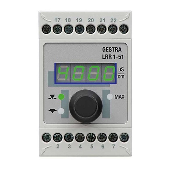
GESTRA LRR 1-50 Original Installation & Operating Manual
Conductivity controller
Hide thumbs
Also See for LRR 1-50:
- Installation & operating instructions manual (28 pages) ,
- Original installation & operating manual (32 pages)

Subscribe to Our Youtube Channel
Related Manuals for GESTRA LRR 1-50


Summary of Contents for GESTRA LRR 1-50
- Page 1 Conductivity Controller LRR 1-50 LRR 1-51 Original Installation & EN (USA) Operating Manual 850702-01 English...
-
Page 2: Table Of Contents
In the plant: Electrically connecting the conductivity electrode/transmitter ......... 22 Connecting conductivity electrode LRG 16-4 ................. 22 Connecting conductivity electrode LRG 16-9 ................. 22 Connecting the LRGT 1.-.. conductivity transmitter ................ 22 LRR 1-50, LRR 1-51 - USA - Installation & Operating Manual - 850702-01... - Page 3 Action against high-frequency interference ................... 33 Taking the LRR 1-50, LRR 1-51 out of service .................. 34 Disposal ............................. 35 UL components ..........................35 Declaration of Conformity Standards and directives ........................35 LRR 1-50, LRR 1-51 - USA - Installation & Operating Manual - 850702-01...
-
Page 4: Content Of This Manual
1 conductivity controller LRR 1-50 1 conductivity controller LRR 1-51 1 adhesive sign for ppm 1 adhesive sign for ppm 1 Installation & Operating Manual 1 Installation & Operating Manual LRR 1-50, LRR 1-51 - USA - Installation & Operating Manual - 850702-01... -
Page 5: How To Use This Manual
How to use this Manual This Installation & Operating Manual describes the correct use of the LRR 1-50, LRR 1-51 conductivity controller. It applies to persons who integrate this equipment in control systems, install, bring into service, operate, maintain and dispose of this equipment. Anyone carrying out the above-mentioned activities must have read this Installation &... -
Page 6: Types Of Warning
Warning of a situation that may result in minor or moderate injury. ATTENTION ATTENTION Warning of a situation that results in damage to property or the environment. LRR 1-50, LRR 1-51 - USA - Installation & Operating Manual - 850702-01... -
Page 7: Specialist Terms, Abbreviations
(flushing interval Si) and opens for a certain time (flushing time Sd). After the flushing time, the valve is moved into the OPERATING position or into the required control position. LRR 1-50, LRR 1-51 - USA - Installation & Operating Manual - 850702-01... -
Page 8: Usage For The Intended Purpose
Usage for the intended purpose The LRR 1-50, LRR 1-51 conductivity controller is used in combination with LRG 1.-.. conductivity electrodes and the LRGT 1.-.. conductivity transmitter as a conductivity controller and limit switch, e.g., in steam boilers and hot water installations or in condensate and feedwater tanks. -
Page 9: Basic Safety Information
Check that the plant is not carrying live voltage before commencing work. ■ Faulty equipment is a danger to plant safety. If the LRR 1-50, LRR 1-51 conductivity controller does not behave as described on ■ this page, it may be faulty. -
Page 10: Function
OPERATING position. If faults occur only in the LRR 1-50, LRR 1-51 conductivity controller, the MAX alarm is trig- gered, the continuous blowdown valve moves into OPERATING position and the system is restart- Parameters can be changed or the MAX alarm simulated by turning the rotary knob. -
Page 11: Technical Data
Approx. 0.44 lb (0.2 kg) Other information Incorporated type 1 action operating control Pollution degree 2, impulse voltage DC supply = 500 V, AC output = 2500 V LRR 1-50, LRR 1-51 - USA - Installation & Operating Manual - 850702-01... -
Page 12: Lrr 1-50 Only
24 hours. Storage temperature -4 ° … 158 °F (-20 ° … +70 °C), only switch on after a defrosting period of 24 hours. Relative humidity Max. 95%, non-condensing LRR 1-50, LRR 1-51 - USA - Installation & Operating Manual - 850702-01... -
Page 13: Factory Default Settings
Password PW: oFF ■ Code switch c: ■ Code switch c: ■ S1: OFF, S2: ON, S3: OFF, S4: OFF S1: OFF, S2: ON, S3: OFF, S4: OFF LRR 1-50, LRR 1-51 - USA - Installation & Operating Manual - 850702-01... -
Page 14: Example Rating Plate/Identification
Tightening: Torque 0.79Nm or 7lb in. Use with accessory: LRGT 16-3, LRGT 16-4, LRGT 17-3 Rating plate of the LRR 1-51, bottom Rating plate of the LRR 1-50, bottom Fig. 1 LRR 1-50, LRR 1-51 - USA - Installation & Operating Manual - 850702-01... -
Page 15: Functional Elements And Dimensions Of The Lrr 1-50, Lrr 1-51
0.6 in (15 mm) 1.81 in (46 mm) 4.72 in (120 mm) Fig. 2 Upper terminal strip Terminal box Lower terminal strip Support rail TH 35, EN 60715 LRR 1-50, LRR 1-51 - USA - Installation & Operating Manual - 850702-01... -
Page 16: Preparing For Installation
Take further measures to protect the equipment from lightning, insects and ■ animals, and salty air. You will need the following tools: Screwdriver size 1/8 in (3.2 mm) ■ LRR 1-50, LRR 1-51 - USA - Installation & Operating Manual - 850702-01... -
Page 17: Installing The Lrr 1-50, Lrr 1-51 Conductivity Controller
Installing the “LRR 1-52”50, “LRR 1-53”1 conductivity controller The LRR 1-50, LRR 1-51 conductivity controller is clipped onto a type TH 35, EN 60715 support rail in the control cabinet. Fig. 2 4 DANGER DANGER There is a risk of electric shock during work on electrical systems. -
Page 18: In The Control Cabinet: Electrically Connecting The Conductivity Controller
MAX output contact (switch-selectable) Supply voltage L2 Conductivity electrode LRG 16-4 (terminal 6/7: Supply voltage N a resistance thermometer can be connected) Central grounding point (CGP) in control cabinet LRR 1-50, LRR 1-51 - USA - Installation & Operating Manual - 850702-01... -
Page 19: Wiring Diagram Of The Lrr 1-51 Conductivity Controller
Supply voltage L2 customer Supply voltage N Actual value/manipulated variable output 4-20 mA (switch-selectable) Conductivity transmitter LRGT 1.-.., 4-20 mA, with grounding point Central grounding point (CGP) in control cabinet LRR 1-50, LRR 1-51 - USA - Installation & Operating Manual - 850702-01... -
Page 20: Connecting The Supply Voltage
Connected inductive loads must therefore have interference suppression (RC combination) as specified by the manufacturer. If used as a conductivity limiter, the LRR 1-50, LRR 1-51 conductivity controller does not interlock automatically when the MAX limit is exceeded. -
Page 21: Connecting The Lrgt 1
UL 60730-1 between the current loop and live parts of the equipment that are not supplied with safety extra-low voltage (SELV). Attention Do not use unused terminals as support terminals. ■ Tools Screwdriver size 1/8 in (3.2 mm) ■ LRR 1-50, LRR 1-51 - USA - Installation & Operating Manual - 850702-01... -
Page 22: In The Plant: Electrically Connecting The Conductivity Electrode/Transmitter
This control cable is not UV-resistant and must be protected with a UV-resistant plastic tube or cable duct if installation is outdoors. For connection to the LRR 1-50 conductivity controller, please remove the connector and wire the terminal strip as shown in the wiring diagram. Fig. 3 Connect the shield to the central grounding point (CGP) in the control cabinet. -
Page 23: Changing The Equipment Settings
Set code switch c as shown in the table below. ■ Insert the lower terminal strip. ■ Switch the supply voltage back on. The equipment restarts. ■ Fig. 5 LRR 1-50, LRR 1-51 - USA - Installation & Operating Manual - 850702-01... -
Page 24: Conductivity Controller Lrr 1-50, Lrr 1-51
* Controller software version 311178.13 or later Attention Do not move switches S1 and S2 on code switch c! Tools Screwdriver size 3.5 x 100 mm, fully insulated to VDE 0680-1. ■ LRR 1-50, LRR 1-51 - USA - Installation & Operating Manual - 850702-01... -
Page 25: Operating The Conductivity Controller
Faulty temperature sensor, temperature reading too high (LRR 1-50 only) E.005 Error Faulty measured value acquisition, reading too low E.006 Error Faulty measured value acquisition, reading too high LRR 1-50, LRR 1-51 - USA - Installation & Operating Manual - 850702-01... -
Page 26: Bringing Into Service
Or after 30 s, the actual value is displayed automatically. If password protection is enabled, you must enter the password before changing a parameter. See section on password protection. LRR 1-50, LRR 1-51 - USA - Installation & Operating Manual - 850702-01... -
Page 27: Conductivity Controller Lrr 1-50: Setting Switchpoints And Parameters
The flushing interval is set between 0 and 24 hours. time. Select parameter Sd, enter and save the de- The flushing time is set between 1 and 4 minutes. sired time. LRR 1-50, LRR 1-51 - USA - Installation & Operating Manual - 850702-01... - Page 28 CF value calculated on this basis. Press and hold the push- button (on rotary knob). CF value is outside the admissible range. The CF.Er previous calibration has been retained. LRR 1-50, LRR 1-51 - USA - Installation & Operating Manual - 850702-01...
-
Page 29: Conductivity Controller Lrr 1-51: Setting Switchpoints And Parameters
The flushing interval is set between 0 and 24 hours. time. Select parameter Sd, enter and save the The flushing time is set between 1 and 4 minutes. desired time. LRR 1-50, LRR 1-51 - USA - Installation & Operating Manual - 850702-01... -
Page 30: Operation, Alarm And Test
TDS below the limit. The blowdown volume is established using the capacity charts of the continuous blowdown valve. Please refer to the Installation & Operating Manual for GESTRA continuous blowdown valves. LRR 1-50, LRR 1-51 - USA - Installation & Operating Manual - 850702-01... -
Page 31: Password Protection
Once disabled, password protection is reactivated after 30 minutes of no activity (i.e., rotary knob is not turned), and the password must be entered again. The parameters are password-protected when the equipment is restarted, if password protection was previously enabled. LRR 1-50, LRR 1-51 - USA - Installation & Operating Manual - 850702-01... -
Page 32: Fault Indications And Troubleshooting
In the event of a fault in the conductivity controller, the MAX alarm is triggered and the equipment restarts. If the process repeats itself continuously, the equipment must be replaced. LRR 1-50, LRR 1-51 - USA - Installation & Operating Manual - 850702-01... -
Page 33: Important Notes
Installation & Operating Manuals. If equalizing currents are likely (outdoor installa- tions), connect the shield on one side only. Suppress HF interference using hinged-shell ferrite rings. ■ LRR 1-50, LRR 1-51 - USA - Installation & Operating Manual - 850702-01... -
Page 34: Taking The Lrr 1-50, Lrr 1-51 Out Of Service
Detach the terminal strip. ■ Release the white slider holder at the bottom of the unit and detach the unit from the support rail. ■ Fig. 7 LRR 1-50, LRR 1-51 - USA - Installation & Operating Manual - 850702-01... -
Page 35: Disposal
Tel. +49 421 3503 0 +49 421 3503 393 e-mail info@de.gestra.com www.gestra.com Modifications to the equipment not approved by us will invalidate Declarations of Conformity and certificates. LRR 1-50, LRR 1-51 - USA - Installation & Operating Manual - 850702-01... - Page 36 You can find our authorized agents around the world at: www.gestra.com GESTRA AG Münchener Straße 77 28215 Bremen Germany Tel. +49 421 3503 0 +49 421 3503 393 e-mail info@de.gestra.com www.gestra.com 850702-01/04-2022cm (809154-01) · GESTRA AG · Bremen...
Need help?
Do you have a question about the LRR 1-50 and is the answer not in the manual?
Questions and answers