GESTRA NRR 2-52 Original Installation Instructions
Level controller, operating & display unit
Hide thumbs
Also See for NRR 2-52:
- Installation & operating manual (68 pages) ,
- Original installation & operating manual (68 pages)

Related Manuals for GESTRA NRR 2-52


Summary of Contents for GESTRA NRR 2-52
- Page 1 Level Controller NRR 2-52 Level Controller NRR 2-53 Operating & Display Unit URB 50 NRR 2-52 NRR 2-53 URB 50 Original Installation Instructions 819222-03 E n g l i s h...
-
Page 2: Table Of Contents
Wiring diagram for level controller NRR 2-53 ..................14 Key ...............................14 In control cabinet: Wiring the operating & display unit Back of equipment, position of connector ....................15 Connection of supply voltage .........................15 Pin assignment for data line NRR 2-52, NRR 2-53 - URB 50 ..............15 Key ...............................15... - Page 3 Establishing measuring range for level electrode NRG 2.-..............25 Setting the control parameters ......................26 Additional information on control parameter settings ................26 Key ...............................26 Setting the control parameters for 3-element control (optional) .............27 Key ...............................27 Only NRR 2-52: Calibrating the potentiometer for indication of valve position ........28...
- Page 4 Contents - continued - Page Operation Manual actuation of control valve ......................28 Trending ..............................29 Key ...............................29 Testing MIN/MAX alarm, entering date and time ...................30 Setting up a password and logging in ....................31 Key ...............................31 Log out ..............................33 Alarm & malfunction list ........................34 Key ...............................34 Error, alarm and warning messages Indication, diagnosis and remedy ......................35...
-
Page 5: Important Notes
Usage for the intended purpose The functional unit consisting of the operating & display unit URB 50 and the level controller NRR 2-52 / NRR 2-53 in conjunction with level electrodes NRG 2.-.. or level transmitter NRGT 26-1 is used as water level controller and as limit switch, for instance in steam boilers, (pressurized) hot-water in stallations as well as condensate and feedwater tanks. -
Page 6: Safety Note
VdTÜV Bulletin "Wasserstand 100" (= Water Level 100) The functional unit consisting of the operating & display unit URB 50 / level controller NRR 2-52, NRR 2-53 in conjunction with level electrode NRG 2.-.. and level transmitter NRGT 26.-.. is type approved according to VdTÜV Bulletin "Wasserüberwachung (= Water Monitoring) 100". -
Page 7: Technical Data
1 analogue output 4-20 mA, max. load 500 ohm (manipulated variable Y). Provide inductive loads with RC combinations according to manufacturer's specification to ensure interference suppression NRR 2-52, NRR 2-53: 1 analogue output 4-20 mA, max. load 500 ohm (e. g. for actual value indication) (optional) Indicators and adjustors... - Page 8 Technical data - continued - NRR 2-52, NRR 2-53 - continued - Weight approx. 0.5 kg Ambient temperature when system is switched on: 0° ... 55 °C, during operation: –10 ... 55°C, Transport temperature –20 ... +80 °C (<100 hours), defrosting time of the de-energized equipment before it can be put into operation: 24 hours.
-
Page 9: Scope Of Supply
–20 ... +70 °C, defrosting time of the de-energized equipment before it can be put into operation: 24 hours. Relative humidity 5 - 85 %, no moisture condensation Scope of supply NRR 2-52 1 Level controller NRR 2-52 1 Installation manual NRR 2-53 1 Level controller NRR 2-53 1 Installation manual URB 50 1 Operating &... -
Page 10: In Control Cabinet: Mounting Level Controller
Housing Lower terminal strip Supporting rail type TH 35, EN 60715 Installation in control cabinet The level controller NRR 2-52, NRR 2-53 is clipped onto the support rail type TH 35, EN 60715 in the control cabinet. Fig. 1 4... -
Page 11: Name Plate / Marking
In control cabinet: Mounting level controller - continued - Name plate / marking Name plate NRR 2-52 Type designation Niveauregler Betriebsanleitung Level Controller beachten Régulateur de niveau Supply Safety note See installation voltage 24 V = instructions 5 VA IP 40 (IP20) -
Page 12: In Control Cabinet: Installing The Operating & Display Unit
In control cabinet: Installing the operating & display unit Dimensions URB 50 Fig. 4 Fig. 3 Fig. 5 Cut-out in control cabinet 136x96 mm Fixing elements Gasket Installation in control cabinet Provide a control panel cut-out with the dimensions indicated in Fig. 3 and 4 . Insert the operating &... -
Page 13: In Control Cabinet: Wiring Level Controller
In control cabinet: Wiring level controller Wiring diagram for level controller NRR 2-52 NRR 2-52 CLOSED OPEN M 0.5 A (semi-delay) Fig. 7 Fixing screws for terminal strip Indication of valve position, potentiometer 0 - 1000 Ω MIN output contact, de-energizing delay: IN 2 / 4-20 mA for feedwater flowrate (optional) 3 sec. -
Page 14: Wiring Diagram For Level Controller Nrr 2-53
In control cabinet: Wiring level controller - continued - Wiring diagram for level controller NRR 2-53 NRR 2-53 M 0.5 A (semi-delay) Fig. 8 Fixing screws for terminal strip Output 4-20 mA manipulated variable Y MIN output contacts 1 and 2 IN 2 / 4-20 mA for feedwater flowrate (optional) De-energizing delay: 3 sec. -
Page 15: In Control Cabinet: Wiring The Operating & Display Unit
Connection of supply voltage +24V # (L-) (L-) Common M Fig. 10 Pin assignment for data line NRR 2-52, NRR 2-53 - URB 50 PIN 2 Data_L PIN 7 Data_H Fig. 11 D-SUB connector with 9 poles for data line... -
Page 16: Connection Of Supply Voltage
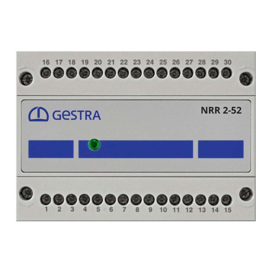
DIN EN 50178, DIN EN 61010-1, DIN EN 60730-1 or DIN EN 60950. After switching on the supply voltage and start-up of the equipment the LED of the level controller NRR 2-52, NRR 2-53 lights up green. Connecting output contacts Wire the upper terminal strip 8 (terminals 16-23) according to the desired and ordered switching functions. -
Page 17: In The Plant
Wiring level electrode / level transmitter Connecting level electrode, level transmitter The level controller NRR 2-52 / NRS 2-53 is designed to be used with level electrodes NRG 21-.. or NRG 26-21 as well as the level transmitter NRGT 26-1. -
Page 18: Level Controller: Changing Factory Settings
Level controller: Changing factory settings Danger The upper terminal strip 8 of the equipment is live during operation. This presents the danger of electric shock! Always cut off power supply to the equipment before mounting, removing or connecting the terminal strips! Changing function and input for level electrode/transmitter The input and the function are determined by the code switch n setting. -
Page 19: Tools
If you want to change the input or the function, set the switches S2 and S3 of the code switch n as indicated in the following table Fig. 12. Code switch Toggle switch, white Level controller NRR 2-52, NRR 2-53 Input for connecting level electrode NRG 21-.. or NRG 26-21 Input for connecting level transmitter NRGT 26-1 *... -
Page 20: Before Putting The Level Control System Into Operation
Before putting the level control system into operation Establishing measuring range Lower end of measuring range, adjustable NRG 2.-.. Upper end of measuring range, adjustable NRGT 26-1 Measuring range [mm] = xxx % Inactive area Max. length of installation at 238 °C Adjust the lower and upper end of the measu- ring range for level control. -
Page 21: Operating & Display Unit Urb 50
If you call up another screen display from the start window and you do not make an entry, the system automatically returns to the start window after approx. 5 minutes (time out). The button is only shown for level controller NRR 2-52 and if a potentiometer is provided for indicating the valve position. -
Page 22: Explanation Of Icons
Position of the control valve if a potentio- valve. This button is only available for the meter is provided for indicating the valve level controller NRR 2-52 and if a potentio- position meter is provided for indicating the valve Position of control valve in case of internal position. - Page 23 Operating & display unit URB 50 - continued - Explanation of icons - continued - Icon Description Icon Description Zooming out of trend curve Get information (magnification decreases) Zooming in on trend curve (magnification increases) Fill control activated Discharge control activated Log in Log out Relay test of MAX switchpoint...
-
Page 24: Commissioning Procedure
Commissioning procedure Adjusting the MIN/MAX switchpoints and setpoint For each setpoint press the green button. Use the on-screen num- berpad Screen display 2 to enter the desired per- centage value. Screen display 1 Numberpad The green buttons in the following windows indicate that user input is possible. -
Page 25: Establishing Measuring Range For Level Electrode Nrg 2
Commissioning - continued - Establishing measuring range for level electrode NRG 2.-.. Only for level electrode NRG 2.-.. : Adjusting lower and upper end of measuring range. The sequence is irrelevant. Press button to open the parameter setting window for the level electrode. Calibrating lower end of measuring range: Lower water level until the lower end of the NRR 2-5:... -
Page 26: Setting The Control Parameters
Commissioning - continued - Setting the control parameters Press button to open the parameter setting window for the controller. NRR 2-5. For each parameter setting press the green button. Use the on-screen numberpad to enter the desired value. Press button to scroll back or press button to go to the parameter... -
Page 27: Setting The Control Parameters For 3-Element Control (Optional)
Commissioning - continued - Setting the control parameters for 3-element control (optional) The buttons for setting the control parameters for 3-element control are only available if the level controller NRR 2-5.. was factory set as 3-element controller. Press button to open the parameter setting window for 3-element control. NRR 2-5. -
Page 28: Only Nrr 2-52: Calibrating The Potentiometer For Indication Of Valve Position
Commissioning - continued - Only NRR 2-52: Calibrating the potentiometer for indication of valve position Press button to open the parameter setting window for the control valve. Press button to switch to manual operating mode. Calibration of "Valve CLOSED"(0%): NRR 2-5. -
Page 29: Trending
Operation - continued - Trending Screen display 1 Press button to open the trend log window. NRR 2-5. Press button to move 1 hour back in the trend log window to zoom out of trend curve (magnification decreases) to zoom in on the trend curve (magnification increases) to move 1 hour forward in the trend log window... -
Page 30: Testing Min/Max Alarm, Entering Date And Time
Testing MIN/MAX alarm, entering date and time Screen display 1 Press button to open the information window NRR 2-52 Testing MIN alarm Press and hold down button L for at least 3 sec. After the de-energizing delay the output contact 17-18 opens and the respective con- tact icon turns red. -
Page 31: Setting Up A Password And Logging In
Operation - continued - Setting up a password and logging in You can allocate a password in order to protect the operating & display unit from unauthorized access and operation. Screen display 11 To log out press button The following button(s) appear(s): Press again button Screen display 13 appears. - Page 32 Operation - continued - Setting up a password and logging in - continued - NRR 2-5. Press button to go to screen display 16 where you can enter a new password. to deactivate the password handling. to go back to the start window. All buttons and input options are now available Screen display 15...
-
Page 33: Log Out
Operation - continued - Log out After having changed the parameters and settings you can log out again. To log out press button The following button(s) appear(s). Press again button Screen display 17 appears. NRR 2-5. NRR 2-5. Press button to go back to the start window. -
Page 34: Alarm & Malfunction List
Operation - continued - Alarm & malfunction list NRR 2-5. Example: Value below MIN switchpoint . The warning triangle O and the change of colour indicate that there is an alarm message. Press the button with the warning triangle O to view the alarm list (screen display 23). -
Page 35: Error, Alarm And Warning Messages
Error, alarm and warning messages Indication, diagnosis and remedy Attention Before carrying out the fault diagnosis please check: Supply voltage: Is the equipment supplied with the voltage specified on the name plate? Wiring: Is the wiring in accordance with the wiring diagram? Alarm list / window Status / error Remedy... -
Page 36: Further Notes
Further Notes Action against high frequency interference High frequency interference can occur for example as a result of out-of-phase switching operations. Should such interference occur and lead to sporadic failures, we recommend the following actions in order to suppress any interference. Provide inductive loads with RC combinations according to manufacturer's specification to ensure interference suppression. - Page 37 For your Notes...
- Page 38 For your Notes...
- Page 39 For your Notes...
- Page 40 Agencies all over the world: www.gestra.de GESTRA AG Münchener Straße 77 28215 Bremen Germany Telefon +49 421 3503-0 Telefax +49 421 3503-393 E-mail info@de.gestra.com www.gestra.de 819222-03/06-2015cm (808865-04) · GESTRA AG · Bremen · Printed in Germany...
Need help?
Do you have a question about the NRR 2-52 and is the answer not in the manual?
Questions and answers