GESTRA NRR 2-52 Installation & Operating Manual
Level controller
Hide thumbs
Also See for NRR 2-52:
- Original installation instructions (40 pages) ,
- Original installation & operating manual (68 pages)

Related Manuals for GESTRA NRR 2-52


Summary of Contents for GESTRA NRR 2-52
- Page 1 Level Controller NRR Visual Display and Operating Unit URB NRR 2-52 NRR 2-53 URB 55 Installation & Operating Manual 850646-00 E n g l i s h...
-
Page 2: Table Of Contents
Connection for 24 V DC supply voltage - pin assignment ................28 Pin assignment of the data line between the URB 55 and the NRR 2-52, NRR 2-53 ........28 NRR 2-52, NRR 2-53, URB 55 - Installation & Operating Manual - 850646-00... - Page 3 Setting the date / time..........................49 Password ..............................49 Network settings ............................50 Data exchange via Modbus TCP ......................... 50 VNC server / Remote software ........................51 NRR 2-52, NRR 2-53, URB 55 - Installation & Operating Manual - 850646-00...
- Page 4 Disposal ................................ 65 Returning decontaminated equipment ......................65 EU Declaration of Conformity - NRR 2-52, NRR 2-53 .................. 66 EU Declaration of Conformity - URB 55......................66 NRR 2-52, NRR 2-53, URB 55 - Installation & Operating Manual - 850646-00...
-
Page 5: Content Of This Manual
1 x power supply connector ■ 1 x data cable URB 55 (L = 5 m) ■ NRR 2-5x + URB 55 1 x Installation & Operating Manual ■ NRR 2-52, NRR 2-53, URB 55 - Installation & Operating Manual - 850646-00... -
Page 6: How To Use This Manual
How to use this Manual This Installation & Operating Manual describes the correct use of the NRR 2-52, NRR 2-53 level controller in combination with the URB 55 visual display and operating unit. It applies to persons who integrate this equipment in control systems, install, bring into service, operate, maintain and dispose of this equipment. -
Page 7: Types Of Warning
Warning of a situation that may result in minor or moderate injury. ATTENTION ATTENTION Warning of a situation that results in damage to property or the environment. NRR 2-52, NRR 2-53, URB 55 - Installation & Operating Manual - 850646-00... -
Page 8: Specialist Terms / Abbreviations
If the actual value reaches the (set point +/- of the neutral zone), the manipulated variable does not change in this range, see page 59. PI controller Controller with proportional (P) and integral (I) control. NRR 2-52, NRR 2-53, URB 55 - Installation & Operating Manual - 850646-00... -
Page 9: Usage For The Intended Purpose
Usage for the intended purpose NRR 2-52 and NRR 2-53 level controllers can be used in combination with NRG 21-xx or NRG 26-21 level electrodes and NRGT 26-x level transmitters as water level controllers and limit switches, e.g. in pressur- ised steam and hot-water plants and in condensate and feedwater tanks. -
Page 10: It Security And Rules For The Use Of Ethernet Devices
■ ual products and networks. Applicable directives and standards - NRR 2-52, NRR 2-53 The NRR 2-52, NRR 2-53 level controller has been tested and approved for use in the scope governed by the following directives and standards: Directives: Directive 2014/35/EU Low Voltage Directive ■... -
Page 11: Applicable Directives And Standards - Urb 55
There is a danger of death due to explosion if the equipment is used in potentially explo- sive atmospheres. Do not use the equipment in potentially explosive atmospheres. NRR 2-52, NRR 2-53, URB 55 - Installation & Operating Manual - 850646-00... -
Page 12: Basic Safety Notes
Check that the system is not carrying live voltage before commencing work. ■ Faulty equipment is a danger to system safety. If the NRR 2-52, NRR 2-53 level controller does not behave as expected, it may be faulty. ■ Perform failure analysis. -
Page 13: Function
Possible combinations of functions and equipment Combining the NRR 2-52, NRR 2-53 level controller with the level electrodes and the URB 55 visual display and operating unit provides the following common functions: Level controller... - Page 14 Display and list of faults, alarms and warnings Test of MIN/MAX output relays Manual/automatic mode Password protection Level and conductivity controllers can be operated simultaneously Fig. 4 NRR 2-52, NRR 2-53, URB 55 - Installation & Operating Manual - 850646-00...
-
Page 15: Technical Data - Nrr 2-52, Nrr 2-53
* Inductive loads must have interference suppression (RC combination) as per the manufacturer's specification ** Contact material AgNi0.15, AgSnO2 Off delay of MIN/MAX alarm outputs Factory default setting 3 seconds. ■ NRR 2-52, NRR 2-53, URB 55 - Installation & Operating Manual - 850646-00... - Page 16 ◆ 2 x 1.5 mm stranded with sleeve ◆ Housing attachment: Mounting clip on support rail TH 35 (to EN 60715) ■ Weight Approx. 0.5 kg ■ NRR 2-52, NRR 2-53, URB 55 - Installation & Operating Manual - 850646-00...
-
Page 17: Technical Data - Urb 55
Front panel (W x H) 147 x 107 mm ■ Switch panel cutout (W x H) 136 mm x 96 mm ■ Depth 52 mm + 8 mm protruding ■ NRR 2-52, NRR 2-53, URB 55 - Installation & Operating Manual - 850646-00... - Page 18 If the equipment is out of service for six months or more, we recommend connecting it to the supply voltage for one day, to recharge the battery. NRR 2-52, NRR 2-53, URB 55 - Installation & Operating Manual - 850646-00...
-
Page 19: Factory Settings - Nrr 2-52, Nrr 2-53
± 20 % of set point ■ Reset time (Ti): 0 seconds ■ Neutral zone: ± 5 % of set point ■ MIN/MAX alarm ■ off delay: 3 seconds (factory set) NRR 2-52, NRR 2-53, URB 55 - Installation & Operating Manual - 850646-00... -
Page 20: Factory Settings - Urb 55
The visual display and operating unit is delivered with the following factory settings: PWL 1: ■ Conductivity in: µS/cm ■ Remote access: ■ Target IP: 192.168.0.84 ■ Subnet: 255.255.255.0 ■ Gateway: 192.168.0.1 ■ Modbus TCP: ■ NRR 2-52, NRR 2-53, URB 55 - Installation & Operating Manual - 850646-00... -
Page 21: Name Plate / Marking - Nrr 2-52
Tamb = T55°C (131°F) 250V ~ T2,5A GESTRA AG xxxxxxxxxxxx Münchener Str. 77 28215 Bremen Made in Germany The date of production is printed on the side of the equipment. NRR 2-52, NRR 2-53, URB 55 - Installation & Operating Manual - 850646-00... -
Page 22: Name Plate / Marking - Nrr 2-53
TÜV.WR.xx-xxx 250V ~ T2,5A GESTRA AG xxxxxxxxxxxx Münchener Str. 77 28215 Bremen Made in Germany The date of production is printed on the side of the equipment. NRR 2-52, NRR 2-53, URB 55 - Installation & Operating Manual - 850646-00... -
Page 23: Name Plate / Marking - Urb 55
Operating Temperature Code T5. Ambient Temp. 60°C For Use on a Flat Surface of a Type 12 4X , ambient temperature Enclosure GESTRA AG Münchener Straße 77 Manufacturer 28215 Bremen www.gestra.com Fig. 9 NRR 2-52, NRR 2-53, URB 55 - Installation & Operating Manual - 850646-00... -
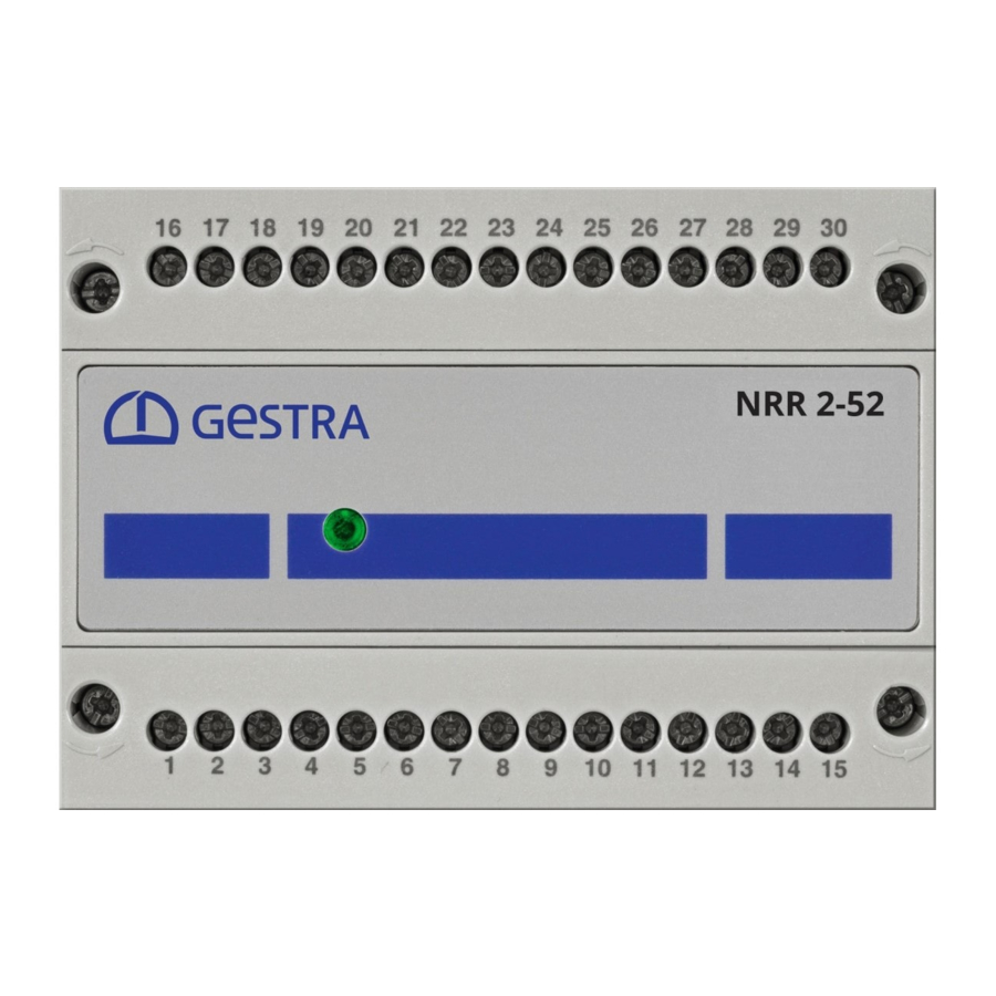
Page 24: Functional Elements And Dimensions - Nrr 2-52, Nrr 2-53
Fastening screws (M3) 4-pole code switch for configuring the level Equipment settings, see page 35. controller Front membrane with status LED, see page 37 Housing Support rail TH 35 NRR 2-52, NRR 2-53, URB 55 - Installation & Operating Manual - 850646-00... -
Page 25: Installing The Nrr 2-52, Nrr 2-53 Level Controller
Installing the NRR 2-52, NRR 2-53 level controller The NRR 2-52, NRR 2-53 level controller snaps onto a TH 35 support rail in a control cabinet. DANGER DANGER There is a risk of electric shock during work on electrical systems. -
Page 26: Dimensions - Urb 55
147 mm 147 mm 52 mm 8 mm Fig. 11 136 mm Required installation aperture in the control cabinet door or switch panel 136 mm Fig. 12 NRR 2-52, NRR 2-53, URB 55 - Installation & Operating Manual - 850646-00... -
Page 27: Installing The Urb 55
Insert the supplied fastening elements and tighten until the corners of the display frame are in contact with the gasket. Remove the protective film from the display. NRR 2-52, NRR 2-53, URB 55 - Installation & Operating Manual - 850646-00... -
Page 28: Connecting The Urb 55
To connect the supply voltage to the supplied 3-pole connector, use a cable with a max. con- ductor size of 2.5 mm Pin assignment of the data line between the URB 55 and the NRR 2-52, NRR 2-53 Pin 2 = Data_L >> NRR 2-52, NRR 2-53 = terminal 12 Pin 7 = Data_H >>... -
Page 29: Safety Notes For Electrical Connection Of The Level Controller
Connect the level controller and all associated components as shown in the wiring ■ diagrams in Fig. 18 / Fig. 19 of this Manual. Do not use unused terminals as jumpers or support terminals. ■ NRR 2-52, NRR 2-53, URB 55 - Installation & Operating Manual - 850646-00... -
Page 30: Wiring Diagram - Nrr 2-52 Level Controller
Actual value output X NRGT 26-x (optional) Display of valve position Analogue input 2 (potentiometer 0 - 1000 W) for feedwater flowrate (optional) Fig. 18 NRR 2-52, NRR 2-53, URB 55 - Installation & Operating Manual - 850646-00... -
Page 31: Wiring Diagram - Nrr 2-53 Level Controller
M0.5A Analogue input 3: – Steam flowrate Actual value output X NRGT 26-x (optional) Analogue output, Analogue input 2: manipulated variable Yw Feedwater flowrate (optional) Fig. 19 NRR 2-52, NRR 2-53, URB 55 - Installation & Operating Manual - 850646-00... -
Page 32: Electrical Connection - Nrr 2-52, Nrr 2-53
Electrical connection - NRR 2-52, NRR 2-53 Connecting the 24 V DC power supply The NRR 2-52 or NRR 2-53 level controller is supplied with 24 V DC. ■ A safety power supply unit that delivers a Safety Extra Low Voltage (SELV) must be used to supply the ■... -
Page 33: Connecting The Data Line Between The Level Controller And The Urb 55
12 of the two controllers to one another as follows: Terminal 11 of controller 1 to terminal 11 of controller 2 ■ Terminal 12 of controller 1 to terminal 12 of controller 2 ■ NRR 2-52, NRR 2-53, URB 55 - Installation & Operating Manual - 850646-00... -
Page 34: Changing The Equipment Settings
Check that the system is not carrying live voltage before commencing work. ■ If necessary, you can change the input and function of the NRR 2-52, NRR 2-53 level controller at any time using code switch D (see Fig. 20). - Page 35 Code switch D Configuration Inlet control (factory setting) Discharge control Input for connecting NRG 21-xx or NRG 26-21 (factory setting) Input for connecting NRGT 26-x (level transmitter) Fig. 20 NRR 2-52, NRR 2-53, URB 55 - Installation & Operating Manual - 850646-00...
-
Page 36: Setting The Measuring Range
Setting the measuring range for the NRGT 26-x level transmitter When connecting the NRGT 26-x level transmitter, please set the upper and lower bounds of the measuring range on the transmitter. NRR 2-52, NRR 2-53, URB 55 - Installation & Operating Manual - 850646-00... -
Page 37: Status Display Of The Nrr 2-52, Nrr 2-53
Status display of the NRR 2-52, NRR 2-53 Fig. 21 Multicolour LED (orange/green/red), orange = power up/green = running/red = malfunction NRR 2-52, NRR 2-53, URB 55 - Installation & Operating Manual - 850646-00... -
Page 38: Visual Display And Operating Unit Urb 55
If just one controller is connected, the home ■ screen of this controller will be shown (example). NRR 2-52, NRR 2-53, URB 55 - Installation & Operating Manual - 850646-00... -
Page 39: Operation And Navigation
Colour coding of input and status fi elds Background colour Description/function Grey Unavailable/static White Input fi eld Green Status information, On, OK status Status information, Alarm status Fig. 22 NRR 2-52, NRR 2-53, URB 55 - Installation & Operating Manual - 850646-00... -
Page 40: Automatic Functions
The keypad shows the old value (Old) and the limits (Min/Max). Your entries must remain within these limits. Function keys: Delete last digit. Confi rm entry. Discard entries and close keypad. NRR 2-52, NRR 2-53, URB 55 - Installation & Operating Manual - 850646-00... -
Page 41: Parameter Input With Password Protection
Scroll bar for long lists and menus You can use the scroll bar to navigate up and down long lists and menus to select the desired parameters. Scroll bar NRR 2-52, NRR 2-53, URB 55 - Installation & Operating Manual - 850646-00... -
Page 42: Icons And Functions - Nrr 2-52, Nrr 2-53
Logged in with password / Alarm history Log off Info Reset alarm Time Alarm number Password Alarm coming Network Alarm going Modbus TCP overview (optional) Reset alarm NRR 2-52, NRR 2-53, URB 55 - Installation & Operating Manual - 850646-00... - Page 43 Start pump in manual mode Max alarm switchpoint Automatic Off/On Min alarm switchpoint Relay test Off/On Max switchpoint Proportional band Min switchpoint Reset time Set point Valve runtime NRR 2-52, NRR 2-53, URB 55 - Installation & Operating Manual - 850646-00...
- Page 44 Icon Description Icon Description Pump 1 On Pump 2 On Pump 1 Off Pump 2 Off Forced pump switchover Fig. 23 NRR 2-52, NRR 2-53, URB 55 - Installation & Operating Manual - 850646-00...
-
Page 45: The Home Screen Of Nrr 2-52, Nrr 2-53 Level Controllers
Boiler level calibration, sections below. see page 58 Set controller parameters, see page 59 Set 3C controller parameters, see page 60 Pump 1 On Pump 2 On Manual (mode) NRR 2-52, NRR 2-53, URB 55 - Installation & Operating Manual - 850646-00... -
Page 46: Alarms And Error Messages
Date and time the event was acknowl- edged and reset. Options: Reset alarms and errors. Once reset, fi nished “alarms” are deleted. Open the alarm history, see page 47. NRR 2-52, NRR 2-53, URB 55 - Installation & Operating Manual - 850646-00... -
Page 47: Opening The Alarm History - Full List Of All Alarms
All alarms are stored in an Alarm History. There is memory capacity for 300 alarms. Alarms are stored in cycles and resto- red after a power failure. Open the Alarm History. NRR 2-52, NRR 2-53, URB 55 - Installation & Operating Manual - 850646-00... -
Page 48: System Settings
Description of display: The connected controller(s) are shown with their software version. Press the button to update a system or view installed (new) units. NRR 2-52, NRR 2-53, URB 55 - Installation & Operating Manual - 850646-00... -
Page 49: Setting The Date / Time
Factory setting: Changing your password: Tap the input field. Enter the new password in the top line and confirm it by entering it again in the second line. NRR 2-52, NRR 2-53, URB 55 - Installation & Operating Manual - 850646-00... -
Page 50: Network Settings
For Modbus communication, switch on the connection using the TCP On button. Parameter: Modbus ID: ■ Port: ■ Modicon Modbus: based on 1 ■ NRR 2-52, NRR 2-53, URB 55 - Installation & Operating Manual - 850646-00... -
Page 51: Vnc Server / Remote Software
This allows a 1:1 display of the URB 55 on the computer. To access the URB 55, use the previously set network parameters. You also need to switch on the service. NRR 2-52, NRR 2-53, URB 55 - Installation & Operating Manual - 850646-00... -
Page 52: Configuring The Level Controller
The set point is shown in the actual value bar chart with a small arrow. Manipulated variable Change of colour on alarm The bar chart column turns red in the event of an alarm. NRR 2-52, NRR 2-53, URB 55 - Installation & Operating Manual - 850646-00... -
Page 53: Automatic / Manual Mode
Pump control in manual mode (example) switched on off. Manual mode is not disabled auto- matically. NRR 2-52, NRR 2-53, URB 55 - Installation & Operating Manual - 850646-00... -
Page 54: Trend Log
Press this button to view the 3C trend. You will then see the actual value (X), corrected actual value (X1), steam fl owrate and, as an option, the water fl owrate. NRR 2-52, NRR 2-53, URB 55 - Installation & Operating Manual - 850646-00... -
Page 55: Test - Testing The Relays Of The Connected Level Controller
Out 1 * Manipulated variable output (Yw) Pump(s) 4 - 20 mA Out 2 * Switch between valve and pump control * * Controller software version 311178.13 or later NRR 2-52, NRR 2-53, URB 55 - Installation & Operating Manual - 850646-00... -
Page 56: Valve Calibration In Manual Mode When A Feedback Potentiometer Is Connected
When the valve is in the (OPEN) end position, confirm the valve position. The raw data from the central field is automatically entered in the 100 % (OPEN) field. NRR 2-52, NRR 2-53, URB 55 - Installation & Operating Manual - 850646-00... -
Page 57: Pump Control
Description of bar chart The “Yw” bar chart shows the manipulated varia- ble of the controller output (4 - 20 mA) normalised to 100 %. NRR 2-52, NRR 2-53, URB 55 - Installation & Operating Manual - 850646-00... -
Page 58: Calibrating The Boiler Level
> 25 % to 100 % using interpolation. When this level is reached, confirm it. The raw data is automatically entered in the 100 % fi eld. NRR 2-52, NRR 2-53, URB 55 - Installation & Operating Manual - 850646-00... -
Page 59: Setting The Level Controller
Correction of deviations starts rapidly zone zone”. Establish the real valve runtime in Valve runtime For NRR 2-52 seconds, e.g. from “Closed” to “Open” only (0 - 100 %). Fig. 24 NRR 2-52, NRR 2-53, URB 55 - Installation & Operating Manual - 850646-00... -
Page 60: Setting The Level Controller For 3-Component Control
For each type of fl owrate, enter the measuring range of the connected sensors for the analogue signal inputs (4 mA / 20 mA). NRR 2-52, NRR 2-53, URB 55 - Installation & Operating Manual - 850646-00... -
Page 61: System Malfunctions - Urb 55
Pump 2 output too low or pump E.026 Replace pump if necessary faulty All fault codes from E.001 to E.027 not listed here are available as reserves Fig. 25 NRR 2-52, NRR 2-53, URB 55 - Installation & Operating Manual - 850646-00... -
Page 62: Common Faults And Issues During Use Of The Urb 55
The URB 55 is not properly connected to the data interface. ■ When two units are connected, the conductivity controller does not switch. Incorrect parameter display Remedy: Reboot the URB 55. NRR 2-52, NRR 2-53, URB 55 - Installation & Operating Manual - 850646-00... -
Page 63: System Malfunctions - Nrr 2-52, Nrr 2-53
Disconnect all poles of the supply cable from the mains and secure so they cannot be ■ switched back on. Check that the system is not carrying live voltage before commencing work. ■ NRR 2-52, NRR 2-53, URB 55 - Installation & Operating Manual - 850646-00... -
Page 64: What To Do In The Event Of System Malfunctions
Remove all plug and socket connections. Unscrew the screws and remove the retaining clips. Carefully push the unit out of the cutout in the door of the control cabinet. NRR 2-52, NRR 2-53, URB 55 - Installation & Operating Manual - 850646-00... -
Page 65: Disposal
GESTRA AG. Such media include solid, liquid or gaseous substances, mixtures of these, or radiation. GESTRA AG can accept returned products only if accompanied by a completed and signed return note and also a completed and signed declaration of decontamination. -
Page 66: Eu Declaration Of Conformity - Nrr 2-52, Nrr 2-53
EU Declaration of Conformity - NRR 2-52, NRR 2-53 We hereby declare that the NRR 2-52, NRR 2-53 level controller conforms to the following European directives: Directive 2014/35/EU Low Voltage Directive ■ Directive 2014/30/EU EMC Directive ■ Directive 2011/65/EU RoHS Directive ■... - Page 67 For your notes NRR 2-52, NRR 2-53, URB 55 - Installation & Operating Manual - 850646-00...
- Page 68 You can find our authorised agents around the world at: www.gestra.com GESTRA AG Münchener Strasse 77 28215 Bremen Germany Phone +49 421 3503-0 +49 421 3503-393 e-mail info@de.gestra.com www.gestra.com 850646-00/03-2021cm (809102-00) · GESTRA AG · Bremen · Printed in Germany...
Need help?
Do you have a question about the NRR 2-52 and is the answer not in the manual?
Questions and answers