GESTRA NRR 2-50 Original Installation & Operating Manual
Level controller
Hide thumbs
Also See for NRR 2-50:
- Installation instructions manual (28 pages) ,
- Original installation & operating manual (36 pages)

Related Manuals for GESTRA NRR 2-50


Summary of Contents for GESTRA NRR 2-50
- Page 1 Level Controller NRR 2-50 NRR 2-51 Original Installation & Operating Manual 819180-05 E n g l i s h...
-
Page 2: Table Of Contents
Supply voltage connection ........................13 Connecting the output contacts ......................13 Connecting the level electrode/level transmitter ..................13 Output of manipulated variable Y or connection of actual value output (optional) ........13 Tools ..............................13 NRR 2-50, NRR 2-51 - Installation & Operating Manual - 819180-05... - Page 3 Checking the function of the MIN/MAX output contacts ...............23 Password protection ..........................24 Troubleshooting Indications, diagnosis and remedies ......................25 Further information Action against high-frequency interference ...................26 Replacing/taking the equipment out of service ..................26 Disposal ..............................26 NRR 2-50, NRR 2-51 - Installation & Operating Manual - 819180-05...
-
Page 4: Important Notes
MAX water level has been reached, and opens or closes a control valve. The NRR 2-50, NRR 2-51 level controller can be combined in a circuit with the NRG 21-.. or NRG 26-21 level electrodes and the NRGT 26-. level transmitters. -
Page 5: Safety Note
Directives and standards VdTÜV Bulletin “Wasserstand 100” (Water Level 100) The NRR 2-50, NRR 2-51 level controller, in combination with the NRG 2.-.. level electrode and NRGT 26-. level transmitter, has type approval in accordance with VdTÜV Bulletin “Wasserstand 100”... -
Page 6: Technical Data
Outputs: NRR 2-50: 2 volt-free relay contacts, 8 A 250 V AC / 30 V DC cos ϕ = 1 (control valve open/closed). 1 volt-free relay contact, 8 A 250 V AC / 30 V DC cos ϕ = 1. -
Page 7: Product Package
(see name plate) Product package NRR 2-50 1 level controller NRR 2-50 1 Installation & Operating Manual NRR 2-51 1 level controller NRR 2-51 1 Installation & Operating Manual NRR 2-50, NRR 2-51 - Installation & Operating Manual - 819180-05... -
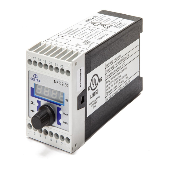
Page 8: Name Plate/Identification
Name plate, bottom Manipulated Actual value variable Y output (optional) Connection of Fuse, level electrode/ provided level transmitter on site Power consumption Supply voltage Approvals Disposal note Fig. 2 NRR 2-50, NRR 2-51 - Installation & Operating Manual - 819180-05... -
Page 9: Installation
The advantage of using the adapter is that the status is visible and alarms can be tested without open- ing the control cabinet door. When installed, the adapter has a rating of IP65. Please refer to the panel adapter Installation & Operating Manual 850625-xx for further information. NRR 2-50, NRR 2-51 - Installation & Operating Manual - 819180-05... -
Page 10: Dimensions Of The Nrr 2-50 / Nrr 2-51
Support rail TH 35, EN 60715 Installation in a control cabinet The NRR 2-50, NRR 2-51 level controller is clipped onto a type TH 35, EN 60715 support rail in the control cabinet. Fig. 1 4 NRR 2-50, NRR 2-51 - Installation & Operating Manual - 819180-05... -
Page 11: In The Control Cabinet: Wiring The Level Controller
Max. three NRS/NRR 2-5.. units can be connected (series connection). Central earthing point (CEP) in control cabinet Output contact for control valve actuation MIN/MAX output contact, off delay 3 seconds Actual value output 4-20 mA NRR 2-50, NRR 2-51 - Installation & Operating Manual - 819180-05... -
Page 12: Wiring Diagram For Level Controller Nrr 2-51
Max. three NRS/NRR 2-5.. units can be connected (series connection). Central earthing point (CEP) in control cabinet MIN output contact, off delay 3 seconds MAX output contact, off delay 3 seconds Output 4-20 mA, manipulated variable Y NRR 2-50, NRR 2-51 - Installation & Operating Manual - 819180-05... -
Page 13: Supply Voltage Connection
(SELV). Attention Do not use unused terminals as support terminals. Tools Screwdriver size 3.5 x 100 mm, fully insulated to VDE 0680-1. NRR 2-50, NRR 2-51 - Installation & Operating Manual - 819180-05... -
Page 14: In The System: Wiring The Level Electrode/Transmitter
Wiring the level electrode/transmitter Connecting the level electrode/level transmitter The NRR 2-50, NRR 2-51 level controller can be combined in a circuit with the NRG 21-.. or NRG 26-21 level electrodes and the NRGT 26-. level transmitter. To connect the equipment, please use a shielded, multi-core control cable with a minimum conductor size of 0.5 mm... -
Page 15: Changing The Factory Settings
Release the terminal strip on the right and left sides, by turning the screwdriver in the direction of the arrow. Remove the terminal strip. Fig. 5 When your changes are complete: Put on the lower terminal strip. Switch the supply voltage back on. The equipment restarts NRR 2-50, NRR 2-51 - Installation & Operating Manual - 819180-05... - Page 16 Please pay attention to the NRGT 26-. Installation & Operating Manual when doing this. Do not change the settings of switch S4 on code switch NRR 2-50, NRR 2-51 - Installation & Operating Manual - 819180-05...
-
Page 17: Operating The Level Controller
E.006 Error Level electrode/transmitter defective, measuring voltage/current too high E.012 Error Lower and upper ends of measuring range wrong way round E.013 Error MIN switchpoint higher than MAX switchpoint NRR 2-50, NRR 2-51 - Installation & Operating Manual - 819180-05... -
Page 18: Setting The Measuring Range
+/- 16% (+/- 32 mm) or in the range of 128 to 192 mm. Larger Slow correction of deviations Responds slowly Integral action Fast correction of deviations, control time Smaller Responds quickly loop may tend to overshoot NRR 2-50, NRR 2-51 - Installation & Operating Manual - 819180-05... -
Page 19: Bringing Into Service
Or after 30s, the actual value is displayed automatically. If password protection is enabled, you must enter the password before you can change parameters. For the password, see page 24. NRR 2-50, NRR 2-51 - Installation & Operating Manual - 819180-05... -
Page 20: Setting The Measuring Range
100% of the measuring range. CAL.P can be adjusted e.g. 25%. between 25 and 100%. Note Adjusting the measuring range: The advantage of option 2 is that the tank only has to be partially filled. NRR 2-50, NRR 2-51 - Installation & Operating Manual - 819180-05... -
Page 21: Operation, Alarm And Testing
The integral action time is set between 10-600 s. percentage. Note The NRR 2-50 level controller is equipped with only one output contact for signalling the limit value. Therefore, please define its function (MAX or MIN alarm) using code switch . -
Page 22: Indications Of Level Controller Nrr 2-50
MAX LED flashes red Off delay in progress. Water level at or above MAX Delay time elapsed, MAX output contacts 21/23 level switchpoint. MAX LED lights up red closed, 22/23 open. NRR 2-50, NRR 2-51 - Installation & Operating Manual - 819180-05... -
Page 23: Checking The Function Of The Min/Max Output Contacts
Turn the rotary knob until the actual value is displayed. Or after 30s, the actual value is displayed automatically. Note The actual value is shown on the 7-segment display. NRR 2-50, NRR 2-51 - Installation & Operating Manual - 819180-05... -
Page 24: Password Protection
Disabled password protection is re-enabled after 30 minutes with no activity (rotary knob). The password must be entered again. When the equipment is restarted, the parameters are password-protected, if password protection was previously enabled. NRR 2-50, NRR 2-51 - Installation & Operating Manual - 819180-05... -
Page 25: Troubleshooting
In the event of a malfunction in the level controller, the MIN and MAX alarm is triggered and the equipment restarts. If the process is continually repeated, the equipment must be replaced. NRR 2-50, NRR 2-51 - Installation & Operating Manual - 819180-05... -
Page 26: Further Information
In the event of malfunctions or faults that cannot be remedied with the aid of this Installation & Operat- ing Manual, please contact our service centre or authorised agent in your country. NRR 2-50, NRR 2-51 - Installation & Operating Manual - 819180-05... - Page 27 For your notes NRR 2-50, NRR 2-51 - Installation & Operating Manual - 819180-05...
- Page 28 You can find our authorised agents around the world at: www.gestra.com GESTRA AG Münchener Straße 77 28215 Bremen Germany Tel. +49 421 3503-0 +49 421 3503-393 E-mail info@de.gestra.com Website www.gestra.com 819180-05/11-2021cm (808863-05) · GESTRA AG · Bremen · Printed in Germany...
Need help?
Do you have a question about the NRR 2-50 and is the answer not in the manual?
Questions and answers