GESTRA NRR 2-52 Original Installation & Operating Manual
Level controller nrr visual display and operating unit urb
Hide thumbs
Also See for NRR 2-52:
- Original installation instructions (40 pages) ,
- Installation & operating manual (68 pages)

Subscribe to Our Youtube Channel
Related Manuals for GESTRA NRR 2-52


Summary of Contents for GESTRA NRR 2-52
- Page 1 Level Controller NRR Visual Display and Operating Unit URB NRR 2-52 NRR 2-53 URB 55 Original Installation & Operating Manual EN (USA) 850698-00 English...
-
Page 2: Table Of Contents
Ports and sockets on the back of the unit ..................28 Connection for 24 V DC supply voltage - pin assignment ..............28 Pin assignment of data line between URB 55 and NRR 2-52, NRR 2-53 .........28 NRR 2-52, NRR 2-53, URB 55 - USA- Installation & Operating Manual - 850698-00... - Page 3 System settings ..........................48 System information ..........................48 Setting the date/time..........................49 Password ............................49 Network settings ..........................50 Data exchange via Modbus TCP .......................50 VNC server / Remote software ......................51 NRR 2-52, NRR 2-53, URB 55 - USA- Installation & Operating Manual - 850698-00...
- Page 4 Checking installation and function ....................64 Taking the NRR 2-52, NRR 2-53 out of service ..................64 Taking out of service URB 55 ......................64 UL components ...........................65 Disposal ..............................65 NRR 2-52, NRR 2-53, URB 55 - USA- Installation & Operating Manual - 850698-00...
-
Page 5: Content Of This Manual
■ 1 x power supply connector ■ 1 x data cable URB 55 ■ NRR 2-5x + URB 55 1 x Installation & Operating Manual ■ NRR 2-52, NRR 2-53, URB 55 - USA- Installation & Operating Manual - 850698-00... -
Page 6: How To Use This Manual
How to use this Manual This Installation & Operating Manual describes the correct use of the NRR 2-52, NRR 2-53 level controller in combination with the URB 55 visual display and operating unit. It applies to persons who integrate this equipment in control systems, install, bring into service, operate, maintain and dispose of this equipment. -
Page 7: Types Of Warning
Warning of a situation that may result in minor or moderate injury. ATTENTION ATTENTION Warning of a situation that results in damage to property or the environment. NRR 2-52, NRR 2-53, URB 55 - USA- Installation & Operating Manual - 850698-00... -
Page 8: Specialist Terms, Abbreviations
Neutral zone If the actual value reaches the (set point +/- of the neutral zone), the manipulated variable does not change in this range, see page 8. NRR 2-52, NRR 2-53, URB 55 - USA- Installation & Operating Manual - 850698-00... -
Page 9: Usage For The Intended Purpose
Usage for the intended purpose NRR 2-52 and NRR 2-53 level controllers can be used in combination with NRGT 26-x level trans- mitters as water level controllers and limit switches, e.g., in steam boilers and hot water installa- tions and in condensate and feedwater tanks. -
Page 10: It Security And Rules For The Use Of Ethernet Devices
■ individual products and networks. Applicable directives and standards - NRR 2-52, NRR 2-53 The NRR 2-52, NRR 2-53 level controller has been tested and approved for use in the scope gov- erned by the following directives and standards: Standards: UL 60730-1 and CAN/CSA E60730-1 ■... -
Page 11: Applicable Directives And Standards - Urb 55
Do not bring any equipment into service that does not have its own specific rating plate. The rating plate indicates the technical features of the equipment. NRR 2-52, NRR 2-53, URB 55 - USA- Installation & Operating Manual - 850698-00... -
Page 12: Basic Safety Information
Check that the plant is not carrying live voltage before commencing work. ■ Faulty equipment is a danger to plant safety. If the NRR 2-52, NRR 2-53 level controller does not behave as expected, it may be ■ faulty. Perform failure analysis. -
Page 13: Function
Possible combinations of functions and equipment Combining the NRR 2-52, NRR 2-53 level controller with level electrodes and the URB 55 visual display and operating unit provides the following common functions: Level controller... - Page 14 Indication and listing of errors, alarms and warnings Test of MIN/MAX output relays Manual/automatic mode Password protection Level and conductivity controllers can be operated simultaneously Fig. 4 NRR 2-52, NRR 2-53, URB 55 - USA- Installation & Operating Manual - 850698-00...
-
Page 15: Technical Data Of The Nrr 2-52, Nrr 2-53
* Inductive loads must have interference suppression (RC combination) in accordance with the manufacturer's specification ** Contact material AgNi0.15, AgSnO2 Off delay of MIN/MAX alarm outputs Factory default setting 3 seconds. ■ NRR 2-52, NRR 2-53, URB 55 - USA- Installation & Operating Manual - 850698-00... - Page 16 ■ Other information Incorporated type 1 action operating control ■ Pollution degree 2, impulse voltage DC supply = 500 V, AC output = 2500 V ■ NRR 2-52, NRR 2-53, URB 55 - USA- Installation & Operating Manual - 850698-00...
-
Page 17: Technical Data Of The Urb 55
Switch panel cutout (W x H) 5.35 in (136 mm) x 3.78 in (96 mm) ■ Mounting depth 2.05 in (52 mm) + 0.32 in (8 mm) protruding ■ NRR 2-52, NRR 2-53, URB 55 - USA- Installation & Operating Manual - 850698-00... - Page 18 If the equipment is out of service for six months or more, we recommend connecting it to the supply voltage for one day, to recharge the battery. NRR 2-52, NRR 2-53, URB 55 - USA- Installation & Operating Manual - 850698-00...
-
Page 19: Factory Default Settings Of The Nrr 2-52, Nrr 2-53
± 20% of set point ■ Reset time (Ti): 0 seconds ■ Neutral zone: ± 5% of set point ■ Off delay for MIN/MAX alarm: 3 seconds (default) ■ NRR 2-52, NRR 2-53, URB 55 - USA- Installation & Operating Manual - 850698-00... -
Page 20: Factory Default Settings Of The Urb 55
The visual display and operating unit is delivered with the following factory default settings: PWL 1: ■ Conductivity in: µS/cm ■ Remote access: ■ Target IP: 192.168.0.84 ■ Subnet: 255.255.255.0 ■ Gateway: 192.168.0.1 ■ Modbus TCP: ■ NRR 2-52, NRR 2-53, URB 55 - USA- Installation & Operating Manual - 850698-00... -
Page 21: Rating Plate, Identification Of The Nrr 2-52
Tightening: Torque 0.79Nm or 7lb in. Tightening: Torque 0.79Nm or 7lb in. Fig. 6 Use with accessory: NRGT 26-2, URB 55 Use with accessory: NRGT 26-2, URB 55 NRR 2-52, NRR 2-53, URB 55 - USA- Installation & Operating Manual - 850698-00... -
Page 22: Rating Plate, Identification Of The Nrr 2-53
Use with accessory: NRGT 26-2, URB 55 Use No.18 16 AWG Wire Size Only, Fig. 8 Tightening: Torque 0.79Nm or 7lb in. Use with accessory: NRGT 26-2, URB 55 NRR 2-52, NRR 2-53, URB 55 - USA- Installation & Operating Manual - 850698-00... -
Page 23: Rating Plate, Identification Of The Urb 55
For Use on a Flat Surface of a Type 12 4X , ambient temperature Enclosure GESTRA AG Münchener Straße 77 Manufacturer 28215 Bremen www.gestra.com Fig. 9 NRR 2-52, NRR 2-53, URB 55 - USA- Installation & Operating Manual - 850698-00... -
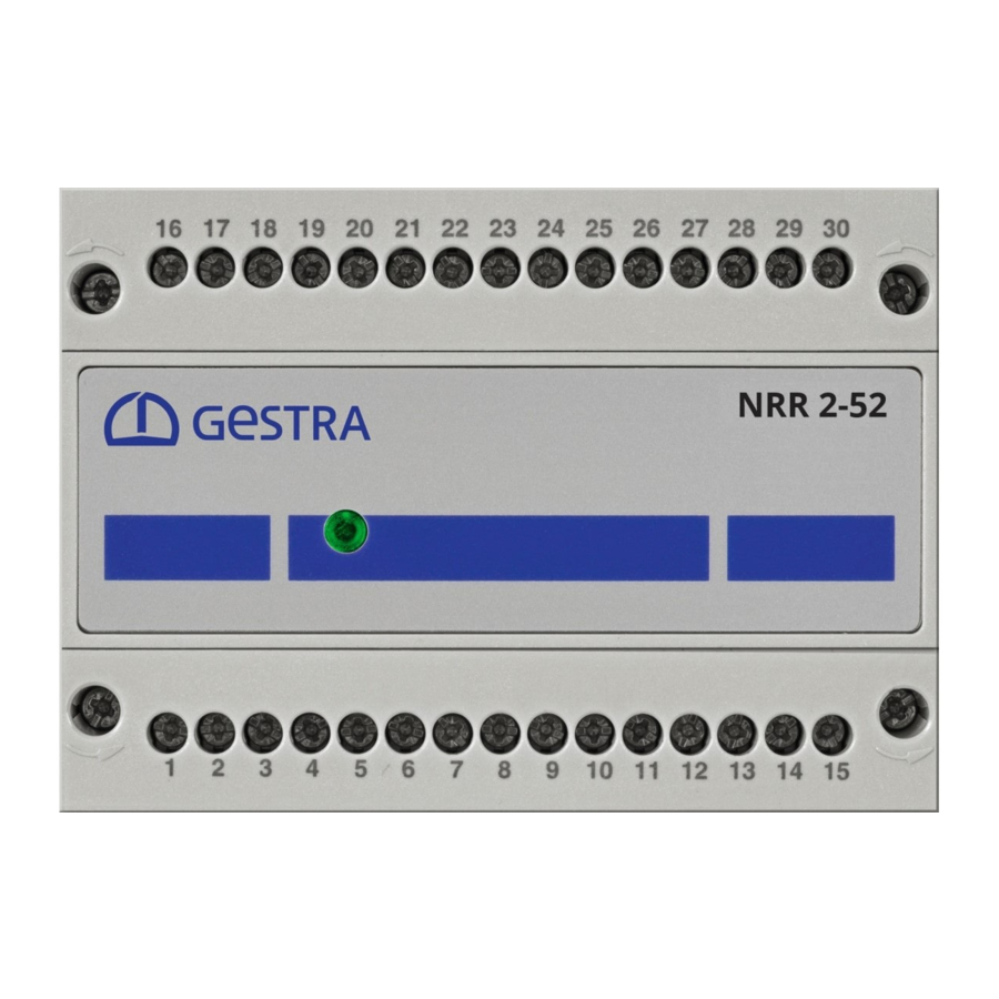
Page 24: Functional Elements And Dimensions Of The Nrr 2-52, Nrr 2-53
4-pole code switch for configuring the Equipment settings, level controller see page 24. Front membrane with status LED, see page 24 Terminal box Support rail TH 35 NRR 2-52, NRR 2-53, URB 55 - USA- Installation & Operating Manual - 850698-00... -
Page 25: Installing The Nrr 2-52, Nrr 2-53 Level Controller
Installing the NRR 2-52, NRR 2-53 level controller The NRR 2-52, NRR 2-53 level controller snaps onto a TH 35 support rail in a control cabinet. DANGER DANGER There is a risk of electric shock during work on electrical systems. -
Page 26: Dimensions Of The Urb 55
2.05 in (52 mm) (8 mm) 5.79 in (147 mm) Fig. 11 Required installation aperture in the control cabinet door or switch panel 5.35 in (136 mm) Fig. 12 NRR 2-52, NRR 2-53, URB 55 - USA- Installation & Operating Manual - 850698-00... -
Page 27: Installing The Urb 55
Insert the supplied fastening elements and tighten until the corners of the display frame are in contact with the gasket. Remove the protective film from the display. NRR 2-52, NRR 2-53, URB 55 - USA- Installation & Operating Manual - 850698-00... -
Page 28: Connecting The Urb 55
Pin 2 = Data_L >> NRR 2-52, NRR 2-53 = terminal 12 Pin 7 = Data_H >> NRR 2-52, NRR 2-53 = terminal 11 Fig. 17 NRR 2-52, NRR 2-53, URB 55 - USA- Installation & Operating Manual - 850698-00... -
Page 29: Safety Information For Electrical Connection Of The Level Controller
Connect the level controller and all associated components as shown in the wiring ■ diagrams in Fig. 18 / NRGT 26-2 of this Manual. Do not use unused terminals as jumpers or support terminals. ■ NRR 2-52, NRR 2-53, URB 55 - USA- Installation & Operating Manual - 850698-00... -
Page 30: Wiring Diagram Of The Nrr 2-52 Level Controller
Actual value output X NRGT 26-2 (optional) Indication of valve position Analog input 2 (potentiometer 0 - 1000 W) for feedwater flowrate (optional) Fig. 18 NRR 2-52, NRR 2-53, URB 55 - USA- Installation & Operating Manual - 850698-00... -
Page 31: Wiring Diagram Of The Nrr 2-53 Level Controller
Analog input 3: – Steam flowrate Actual value output X NRGT 26-2 (optional) Analog output, Analog input 2: manipulated variable Yw Feedwater flowrate (optional) Fig. 19 NRR 2-52, NRR 2-53, URB 55 - USA- Installation & Operating Manual - 850698-00... -
Page 32: Electrical Connection Of The Nrr 2-52, Nrr 2-53
Electrical connection of the NRR 2-52, NRR 2-53 Connecting the 24 V DC power supply The NRR 2-52 or NRR 2-53 level controller is supplied with 24 V DC. ■ A safety power supply unit that delivers a Safety Extra Low Voltage (PELV / CLASS2) must be ■... -
Page 33: Connecting The Data Line Between The Level Controller And The Urb 55
11 and 12 of the two controllers to one another as follows: Terminal 11 (controller 1) to terminal 11 of controller 2 ■ Terminal 12 (controller 1) to terminal 12 of controller 2 ■ NRR 2-52, NRR 2-53, URB 55 - USA- Installation & Operating Manual - 850698-00... -
Page 34: Changing The Equipment Settings
Check that the plant is not carrying live voltage before commencing work. ■ If necessary, you can change the input and function of the NRR 2-52, NRR 2-53 level controller at any time using code switch D (see Fig. 20). - Page 35 NRR 2-52, NRR 2-53 level controller Code switch D Configuration Fill control (factory setting) Drain control Input for connecting an NRGT 26-x (level transmitter) Fig. 20 NRR 2-52, NRR 2-53, URB 55 - USA- Installation & Operating Manual - 850698-00...
-
Page 36: Setting The Measuring Range
Setting the measuring range for the NRGT 26-2 level transmitter When connecting the NRGT 26-2 level transmitter, you need to set the upper and lower bounds of the measuring range on the transmitter. NRR 2-52, NRR 2-53, URB 55 - USA- Installation & Operating Manual - 850698-00... -
Page 37: Status Display Of The Nrr 2-52, Nrr 2-53
Status display of the NRR 2-52, NRR 2-53 Fig. 21 Multicolor LED (amber/green/red), amber = power up/green = running/red = malfunction NRR 2-52, NRR 2-53, URB 55 - USA- Installation & Operating Manual - 850698-00... -
Page 38: Visual Display And Operating Unit Urb 55
If just one controller is connected, the ■ home screen of this controller will be shown (example). NRR 2-52, NRR 2-53, URB 55 - USA- Installation & Operating Manual - 850698-00... -
Page 39: Operation And Navigation
Color coding of input and status fields Background color Description, function Gray Unavailable/static White Input field Green Status information, On, OK status Status information, Alarm status Fig. 21 NRR 2-52, NRR 2-53, URB 55 - USA- Installation & Operating Manual - 850698-00... -
Page 40: Automatic Functions
The keypad shows the old value (Old) and the limits (Min/Max). Your entries must remain within these limits. Function keys: Delete last digit. Confirm entry. Discard entries and close keypad. NRR 2-52, NRR 2-53, URB 55 - USA- Installation & Operating Manual - 850698-00... -
Page 41: Entering Parameters With Password Protection
Scroll bar for long lists and menus You can use the scroll bar to navigate up and down long lists and menus in order to select the desired parameters. Scroll bar NRR 2-52, NRR 2-53, URB 55 - USA- Installation & Operating Manual - 850698-00... -
Page 42: Icons And Functions Of The Nrr 2-52, Nrr 2-53
Logged in with password/ Alarm history Log off Info Reset alarm Time Alarm number Password Alarm coming Network Alarm going Modbus TCP overview (optional) Reset alarm NRR 2-52, NRR 2-53, URB 55 - USA- Installation & Operating Manual - 850698-00... - Page 43 Start pump in manual mode Max alarm switchpoint Automatic Off/On Min alarm switchpoint Relay test Off/On Max switchpoint Proportional band Min switchpoint Reset time Set point Valve runtime NRR 2-52, NRR 2-53, URB 55 - USA- Installation & Operating Manual - 850698-00...
- Page 44 Icon Description Icon Description Pump 1 On Pump 2 On Pump 1 Off Pump 2 Off Forced pump switchover Fig. 22 NRR 2-52, NRR 2-53, URB 55 - USA- Installation & Operating Manual - 850698-00...
-
Page 45: Home Screen Of Nrr 2-52, Nrr 2-53 Level Controllers
Boiler level calibration, see page 45 Set controller parameters, see page 45 Set 3E controller parameters, Pump 1 On see page 45 Pump 2 On Manual (mode) NRR 2-52, NRR 2-53, URB 55 - USA- Installation & Operating Manual - 850698-00... -
Page 46: Alarm And Fault Indications
Date and time the event was reset. Options: Reset alarms and errors. Finished “alarms” are deleted after they have been reset. Open the alarm history, see page 46. NRR 2-52, NRR 2-53, URB 55 - USA- Installation & Operating Manual - 850698-00... -
Page 47: Opening The Alarm History
All alarms are stored in the alarm history. The memory can hold 300 alarms. Alarms are stored cyclically and are restored after a power failure. Open the alarm history. NRR 2-52, NRR 2-53, URB 55 - USA- Installation & Operating Manual - 850698-00... -
Page 48: System Settings
Description of display: The connected controller(s) are shown with their software version. Press the button to update a system or view installed (new) equipment. NRR 2-52, NRR 2-53, URB 55 - USA- Installation & Operating Manual - 850698-00... -
Page 49: Setting The Date/Time
Changing your password: Tap the input field. Enter the new password in the top line and confirm it by entering it again in the second line. NRR 2-52, NRR 2-53, URB 55 - USA- Installation & Operating Manual - 850698-00... -
Page 50: Network Settings
For Modbus communication, switch on the connection using the TCP On button. Parameter: Modbus ID: ■ Port: ■ Modicon Modbus: 1-based ■ NRR 2-52, NRR 2-53, URB 55 - USA- Installation & Operating Manual - 850698-00... -
Page 51: Vnc Server / Remote Software
Viewer. This allows a 1:1 display of the URB 55 on the computer. To access the URB 55, use the previously set network parameters. You also need to switch on the service. NRR 2-52, NRR 2-53, URB 55 - USA- Installation & Operating Manual - 850698-00... -
Page 52: Configuring The Level Controller
Manipulated variable Change of color on alarm The bar chart column turns red in the event of an alarm. NRR 2-52, NRR 2-53, URB 55 - USA- Installation & Operating Manual - 850698-00... -
Page 53: Automatic/Manual Mode
Pump control in manual mode (example) variable is entered and the pump is switched on off. Manual mode is not disabled automatically. NRR 2-52, NRR 2-53, URB 55 - USA- Installation & Operating Manual - 850698-00... -
Page 54: Trend Log
Press this button to view the 3E trend. You will then see the actual value (X), corrected actual value (X1), steam flowrate and, as an option, the water flowrate. NRR 2-52, NRR 2-53, URB 55 - USA- Installation & Operating Manual - 850698-00... -
Page 55: Test - Testing The Relays Of The Connected Level Controller
Manipulated variable output (Yw) Pump(s) 4 - 20 mA Out 2 * Switch between valve and pump control * * Controller software version 311178.13 or later NRR 2-52, NRR 2-53, URB 55 - USA- Installation & Operating Manual - 850698-00... -
Page 56: Valve Calibration In Manual Mode When A Feedback Potentiometer Is Connected
When the valve is in the (OPEN) end position, confirm this position. The raw data from the central field is automatically entered in the 100% (OPEN) field. NRR 2-52, NRR 2-53, URB 55 - USA- Installation & Operating Manual - 850698-00... -
Page 57: Pump Control
Description of bar chart The(Yw) bar chart shows the manipulated variable of the controller output (4 - 20 mA) normalized to 100%. NRR 2-52, NRR 2-53, URB 55 - USA- Installation & Operating Manual - 850698-00... -
Page 58: Calibrate The Boiler Level (For Nrg2
> 25% to 100% using interpolation. When this level is reached, confirm it. The raw data is automatically entered in the 100% field. NRR 2-52, NRR 2-53, URB 55 - USA- Installation & Operating Manual - 850698-00... -
Page 59: Setting The Level Controller
“neutral zone zone”. For NRR Establish the real valve runtime in Valve runtime 2-52 seconds, e.g., from “Closed” to “Open” only (0 - 100%). Fig. 23 NRR 2-52, NRR 2-53, URB 55 - USA- Installation & Operating Manual - 850698-00... -
Page 60: Setting The Level Controller For 3-Element Control
For each type of flowrate, enter the measuring range of the connected sensors for the analog signal inputs (4 mA / 20 mA). NRR 2-52, NRR 2-53, URB 55 - USA- Installation & Operating Manual - 850698-00... -
Page 61: System Malfunctions In The Urb 55
Pump 2 output too low or pump E.026 faulty Replace pump if necessary All error codes from E.001 to E.027 not listed here are available as reserves Fig. 24 NRR 2-52, NRR 2-53, URB 55 - USA- Installation & Operating Manual - 850698-00... -
Page 62: Common Faults And Issues During Use Of The Urb 55
The URB 55 is not correctly connected to the data interface. ■ The conductivity controller is not switched over when two units are connected. Incorrect parameter display Remedy: Reboot the URB 55. NRR 2-52, NRR 2-53, URB 55 - USA- Installation & Operating Manual - 850698-00... -
Page 63: System Malfunctions In The Nrr 2-52, Nrr 2-53
Disconnect all poles of the supply cable from the mains and secure so it cannot be ■ switched back on. Check that the plant is not carrying live voltage before commencing work. ■ NRR 2-52, NRR 2-53, URB 55 - USA- Installation & Operating Manual - 850698-00... -
Page 64: What To Do In The Event Of System Malfunctions
Unplug all plug and socket connections. Unscrew the screws and remove the retaining clips. Carefully push the unit out of the cutout in the door of the control cabinet. NRR 2-52, NRR 2-53, URB 55 - USA- Installation & Operating Manual - 850698-00... -
Page 65: Ul Components
UL components NRR 2-52 and NRR 2-53 level controllers are registered under XACN.E513189. The URB 55 visual display and operating unit is registered under E514624. NRR 2-52, NRR 2-53, URB 55 - USA- Installation & Operating Manual - 850698-00... - Page 66 For your notes NRR 2-52, NRR 2-53, URB 55 - USA- Installation & Operating Manual - 850698-00...
- Page 67 For your notes NRR 2-52, NRR 2-53, URB 55 - USA- Installation & Operating Manual - 850698-00...
- Page 68 You can find our authorized agents around the world at: www.gestra.com GESTRA AG Münchener Straße 77 28215 Bremen Germany Tel. +49 421 3503 0 +49 421 3503 393 e-mail info@de.gestra.com www.gestra.com 850698-00/08-2021cm (809146-00) · GESTRA AG · Bremen...
Need help?
Do you have a question about the NRR 2-52 and is the answer not in the manual?
Questions and answers