GESTRA LRR 1-50 Installation & Operating Instructions Manual
Steam systems conductivity controller
Hide thumbs
Also See for LRR 1-50:
- Original installation & operating manual (32 pages) ,
- Original installation & operating manual (36 pages)

Related Manuals for GESTRA LRR 1-50


Summary of Contents for GESTRA LRR 1-50
- Page 1 GESTRA Steam Systems LRR 1-50 English LRR 1-51 Installation & Operating Instructions 819224-03 Conductivity Controller LRR 1-50 Conductivity Controller LRR 1-51...
-
Page 2: Table Of Contents
Dimensions LRR 1-50, LRR 1-51 ......................11 Key ...............................11 Installation in control cabinet .........................11 In control cabinet: Wiring the conductivity controller Wiring diagram for conductivity controller LRR 1-50 ................12 Key ...............................12 Wiring diagram for conductivity controller LRR 1-51 ................13 Key ...............................13 Connection of supply voltage .........................14... - Page 3 Operating the conductivity controller Key to codes on seven-segment display ....................19 Commissioning procedure Setting parameters..........................20 Conductivity controller LRR 1-50: Setting switchpoints and parameters ..........21 Conductivity controller LRR 1-51: Setting switchpoints and parameters ..........22 Operation, alarm and test Conductivity controller LRR 1-50, LRR 1-51: Indications and checking the functions of the MAX output contacts ............23...
-
Page 4: Important Notes
Important notes Usage for the intended purpose The conductivity controller LRR 1-50, LRR 1-51 in conjunction with conductivity electrodes LRG 1.-.. and conductivity transmitter LRGT 1.-.. is used as conductivity controller and limit switch, for instance in steam boilers, (pressurized) hot-water installations as well as condensate and feedwater tanks. The conductivity controller indicates when the MAX conductivity limit is reached and opens or closes a continuous blowdown valve. -
Page 5: Function
MAX alarm will be raised and the continuous blowdown valve is motored into the OPERA- TING position. If the malfunction occurs only in the conductivity controller LRR 1-50, LRR 1-51 a MAX alarm will be raised, the continuous blowdown controller is motored into the OPERATING position and the system is re-started. -
Page 6: Safety Note
Important notes – continued – Safety note The equipment must only be installed, wired and commissioned by qualified and competent staff. Retrofitting and maintenance work must only be performed by qualified staff who - through adequate training - have achieved a recognised level of competence. Danger The terminal strips of the equipment are live during operation. -
Page 7: Directives And Standards
(pressurised) hotwater installations. VdTÜV Bulletin “Water Monitoring 100” The conductivity controller LRR 1-50, LRR 1-51 in conjunction with conductivity electrode LRG 1.-.. and conductivity transmitter LRGT 1.-.. is type approved according to VdTÜV Bulletin “Wasserüberwachung (= Water Monitoring) 100”. The VdTÜV Bulletin “Water Monitoring 100” states the requirements made on water monitoring equipment. -
Page 8: Technical Data
Technical data LRR 1-50, LRR 1-51 Supply voltage 24 VDC +/– 20% Fuse external 0.5 A (semi-delay) Power consumption 4 VA Reset hysteresis MAX limit: – 3 % of the adjusted MAX limit, fixed setting Outputs 2 volt-free change-over contacts, 8 A 250 V AC / 30 V DC cos ϕ = 1 (continuous blowdown valve OPEN, OPERATING, CLOSED). -
Page 9: Only Lrr 1-50
Requirements made on water monitoring equipment Type approval no. TÜV · WÜL · 12-017 (see nameplate) Scope of supply LRR 1-50 LRR 1-51 1 Conductivity switch LRR 1-50 1 Conductivity switch LRR 1-51 1 Adhesive plate ppm 1 Adhesive plate ppm 1 Installation manual... -
Page 10: Name Plate / Marking
Technical data – continued – Name plate / marking Nameplate LRR 1-50, LRR 1-51 on top Nameplate LRR 1-50 below Type Safety Manufacturer designation note Connection actual value output Fuse, provided Connection on site for conductivity electrode Power consumption Protection... -
Page 11: In Control Cabinet: Installing The Conductivity Controller
Housing Lower terminal strip Supporting rail type TH 35, EN 60715 Installation in control cabinet The conductivity controller LRR 1-50, LRR 1-51 is clipped onto the support rail type TH 35, EN 60715 in the control cabinet. Fig. 1 4... -
Page 12: In Control Cabinet: Wiring The Conductivity Controller
In control cabinet: Wiring the conductivity controller Wiring diagram for conductivity controller LRR 1-50 OPEN CLOSED OPERATING Actuator EF M 0.5 A M 0.5 A L2 must remain live after the burner (stand- by operation) - and therefore also the supply... -
Page 13: Wiring Diagram For Conductivity Controller Lrr 1-51
In control cabinet: Wiring the conductivity controller – continued – Wiring diagram for conductivity controller LRR 1-51 OPEN CLOSED OPERATING Actuator EF L2 must remain live after the burner (stand- by operation) - and therefore also the supply voltage for the controller - is shut down until the actuator has closed the continuous blow- down valve. -
Page 14: Connection Of Supply Voltage
RC combinations as specified by the manu- facturer. When used as conductivity limiter the conductivity controller LRR 1-50, LRR 1-51 does not interlock automatically when the readings exceed the MAX limit. -
Page 15: Connection Of Conductivity Transmitter Lrgt 1
In control cabinet: Wiring the conductivity controller – continued – Connection of conductivity transmitter LRGT 1.-.. To connect the equipment use screened multi-core control cable with a min. conductor size 0.5 mm², e. g. LiYCY 4 x 0.5 mm , max. length 100 m. Wire terminal strip in accordance with the wiring diagram. -
Page 16: In The Plant: Wiring The Conductivity Electrode / Transmitter
Note that the recommended control cable is not UV-resistant and, if installed outdoors, must be protected by a UV-resistant plastic tube or cable duct. To connect the conductivity controller LRR 1-50 remove the connector and wire the terminal strip according to the wiring diagram. Fig. 3 Connect the screen only once to the central earthing point (CEP) in the control cabinet. -
Page 17: Factory Settings
Factory settings Conductivity controller LRR 1-50 Conductivity controller LRR 1-51 MAX switchpoint AL.Hi = 6000 μS/cm MAX switchpoint AL.Hi = 6000 μS/cm Setpoint SP = 3000 μS/cm Setpoint SP = 3000 μS/cm Dead band: +/– 5 % of setpoint Dead band: +/– 5 % of setpoint... -
Page 18: Changing Factory Settings
Changing factory settings Danger The upper terminal strip of the equipment is live during operation. This presents the danger of electric shock! Always cut off power supply to the equipment before mounting, removing or connecting the terminal strips! Switch selection of unit of measurement The electrical conductivity is measured in µS/cm. -
Page 19: Operating The Conductivity Controller
Setpoint Setpoint, adjustable between 1 and 9999 μS/cm HySt Hysteresis Reset hysteresis, adjustable between 1 and 25 % of the setpoint Only LRR 1-50 Only LRR 1-51 Correction Correction factor, adjustable between 0.05 Lower end of measuring range, adjustable Sin.L Factor and 5,000, adjustable in increments of 0.001... -
Page 20: Commissioning Procedure
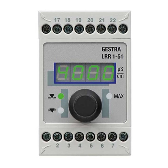
Commissioning procedure Setting parameters 5432 Seven-segment Rotary button display with integrated push-button LED 1 MAX LED red Valve opens LED 2 Valve closes Fig. 5 Start Activity Display Function Seven-segment display shows equip- System test, takes approx. 3 sec. ment and software version Switch on supply voltage. -
Page 21: Conductivity Controller Lrr 1-50: Setting Switchpoints And Parameters
Commissioning procedure – continued – Conductivity controller LRR 1-50: Setting switchpoints and parameters Setting the MAX switchpoint Activity Function Select parameter AL.HI, set the desired conductivity and Adjust MAX limit between 1 and 9999 μS/cm or 1 and save the setting. -
Page 22: Conductivity Controller Lrr 1-51: Setting Switchpoints And Parameters
Commissioning procedure – continued – Conductivity controller LRR 1-51: Setting switchpoints and parameters 5432 Seven-segment Rotary button display with integrated push-button LED 1 MAX LED red Valve opens LED 2 Valve closes Fig. 5 Setting the MAX switchpoint Activity Function Select parameter AL.HI, set the desired conductivity and Adjust MAX limit between 1 and 9999 μS/cm or 1 and save the setting. -
Page 23: Operation, Alarm And Test
TDS (= total dissolved solids) level below the limit. The amount of boiler blowdown can be ascertained by means of the capacity charts for the continuous blowdown valve. Please observe the installation instructions of the GESTRA continuous blowdown valve. -
Page 24: Troubleshooting
Troubleshooting Indication, diagnosis and remedy Attention Before carrying out the fault diagnosis please check: Supply voltage: Is the equipment supplied with the mains voltage specified on the name plate? Wiring: Is the wiring in accordance with the wiring diagram? Faults indicated by the seven-segment display Error code Error Remedy... -
Page 25: Further Notes
Further notes Action against high frequency interference High frequency interference can occur for example as a result of out-of-phase switching operations. Should such interference occur and lead to sporadic failures, we recommend the following actions in order to suppress any interference. Provide inductive loads with RC combinations according to manufacturer's specification to ensure interference suppression. - Page 26 For your notes...
- Page 27 For your notes...
- Page 28 Agencies all over the world: www.gestra.de GESTRA AG Münchener Straße 77 28215 Bremen Germany Telefon +49 421 3503-0 Telefax +49 421 3503-393 E-mail info@de.gestra.com www.gestra.de 819224-03/04-2017csa (808889-03) · GESTRA AG · Bremen · Printed in Germany...
Need help?
Do you have a question about the LRR 1-50 and is the answer not in the manual?
Questions and answers