Table of Contents
Advertisement
Quick Links
Advertisement
Table of Contents
Troubleshooting

Subscribe to Our Youtube Channel
Related Manuals for GESTRA NRR 2-40


Summary of Contents for GESTRA NRR 2-40
- Page 1 NRR 2-40 Installation Instructions 810369-03 Level Controller Type NRR 2-40...
-
Page 2: Table Of Contents
Wiring diagram ....................3, 4, 10, 11 Basic Adjustments CAN bus ........................12 Node ID ......................... 12 Factory setting ......................13 Controller NRR 2-40 ..................... 13 Commissioning NRR 2-40 ........................14 Control range ........................ 14 Adjusting the control range ..................14, 15 Establishing switchpoints and proportional band .......... - Page 3 Wiring Diagram NRR 2-40 as three-position stepping controller Paired cable Paired cable Fig. 1 Fig. 2...
- Page 4 Wiring Diagram NRR 2-40 as continuous controller Paired cable Paired cable Fig. 3 Control terminal and display unit Level switch Level controller Level electrode Sensor URB 1 NRS 1-42 NRR 2-40 NRG 16-42 . . . CEP*) Voltage supply CAN data line...
- Page 5 Parts Drawings Fig. 5 Fig. 6...
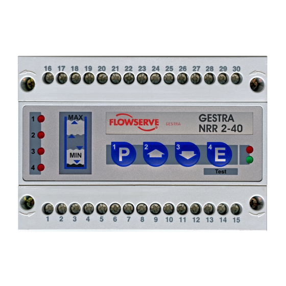
- Page 6 Indicator LED Alarm Malfunction LED 1 – Switchpoint 1 High-level Multifunction not allocated Multifunction LED 2 – Control valve closing Multifunction LED 3 – Control valve opening not allocated Multifunction LED 4 – Switchpoint 4 Low-level LED “Bus status” LED “Power” Enter button / Test mode Decrease button Increase button...
-
Page 7: Important Notes
Important Notes Usage for the intended purpose Use level controller NRR 2-40 in combination with level electrode NRG 26-40 only for controlling the liquid level of conductive fluids. Safety Note The equipment must only be installed by qualified staff. Qualified staff are those persons who – through adequate training in electrical engineering, the use and application of safety equipment in accordance with regulations concerning electrical safety systems, and first aid &... -
Page 8: Explanatory Notes
Continuous level monitoring within the control band defined by two preset limits The NRR 2-40 features an optional output for a standard signal 4 – 20 mA. The level data are transferred from the electrode NRG 26-40 to the level controller via a CAN data bus. -
Page 9: Technical Data
Technical Data Type approval no. NRR 2-40: TÜV 98-399 Input / Output Interface for CAN bus to DIN ISO 11898 CANopen Feedback potentiometer 1000 Ω Output – voltage supply for electrodes Power supply 24 V DC, short-circuit protected. Analogue output 4 – 20 mA, load 500 Ω for display of actual value (option). -
Page 10: Installation
Installation NRR 2-40 Installation on mounting rail 1. Clip level controller onto mounting rail 35 x 15 mm (DIN EN 50022). 2. Align level controller, fig. 19, 20. Tool Screwdriver (5.5/100) Wiring Note that screened multi-core twisted-pair control cable is required, e. g. - Page 11 Wiring – continued – Attention Wire equipment in series. Star-type wiring is not permitted. Interlink screens of control cables such that electrical continuity is ensured and connect them once to the central earthing point (CEP). To protect the switching contacts fuse circuit with 2.5 A (slow blow) or according to TRD regulations.
-
Page 12: Basic Adjustments
The CAN address (node ID) can be set between 1 and 123. The NRR 2-40 is configured at our works and ready for service with other GESTRA system components without having to set the node ID. -
Page 13: Factory Setting
Fig. 7 Controller NRR 2-40 The controller type NRR 2-40 is specially designed for level control in steam boilers and feedwater deaerators. The NRR 2-40 is a proportional controller with steady- state deviation. The positive and negative deviation lies within the proportional band ) preselected by the user. -
Page 14: Commissioning
Commissioning NRR 2-40 Apply power to the unit. Indicator LEDs flash rapidly The four indicator LEDs flash rapidly. The LED “Power” lights up. The test cycle takes about two seconds. LED “Power” illuminated. Control Range Desired control range [mm] Max. control range... - Page 15 Press button briefly. LEDs illuminated LEDs flash slowly briefly Press button twice briefly. The upper limit of the desired control range is now saved. The NRR 2-40 is now again in operating mode. twice briefly...
- Page 16 Commissioning – continued – Switchpoints and proportional band Switchpoint 1 Switchpoint 2 Switchpoint 3 Switchpoint 4 NRG 26-40 Selected control range Fig. 9 You can establish two switchpoints and a proportional band X within the control range. 80 % 90 % 70 % 20 % 50 %...
-
Page 17: Establishing Switchpoints And Proportional Band
Commissioning – continued – Establishing switchpoints and proportional band Press button briefly. LED illuminated LEDs flash slowly Raise or lower the liquid level in the vessel until the desired value is reached. Use button if you first want to establish the proportional band or a different switchpoint. - Page 18 Commissioning – continued – Establishing switchpoints and proportional band – continued – Press button briefly. LED illuminated LEDs flash slowly Switchpoint 3 is now saved. briefly Press button briefly. LED illuminated LEDs flash slowly The upper limit of the proportional band is now selected (switchpoint 2).
-
Page 19: Establishing Switchpoints And Proportional Band
LED flashes LEDs flash slowly Raise liquid level until switchpoint 1 within the desired control range is reached. briefly Press button twice briefly. LED illuminated Switchpoint 1 is now saved. The NRR 2-40 is now again in operating mode. twice briefly... -
Page 20: Calibrating The Feedback Potentiometer Of An External Control Valve
Fig. 12 Attention The GESTRA level controller type NRR 2-40 requires a 1000 Ω Ω Ω Ω Ω feedback potentiometer. The NRR 2-40 works as two-position controller when the terminals for the feedback potentiometer are not wired or the feedback potentiometer is defective. -
Page 21: Operation
Operation Normal operation Normal operation, controller is working. LEDs flash when the control valve is motored The green LEDs 2 and 3 flash when the external control valve is opened or closed. All LEDs go out when the setpoint is reached. -
Page 22: Relay Test High/Low-Level Alarm
Max. admissible temperature in electrode terminal box exceeded No or faulty communication between controller and electrode Malfunction in CAN bus Failure of 24 V power supply unit built in level controller NRR 2-40 Attention The terminal strip of the NRR 2-40 is live during operation. -
Page 23: System Malfunctions
System Malfunctions – continued – Systematic Malfunction Analysis The sources of malfunctions occurring in CAN bus systems operating with several bus-based stations must be analysed systematically since faulty components or incorrect settings can give rise to negative interactions with intact bus devices in the CAN bus system. - Page 24 System Malfunctions – continued – System malfunction 1 LEDs flash slowly The four indicator LEDs flash slowly. High/low-level alarm Fault: The max. admissible temperature in the electrode terminal box is exceeded. Remedy: Insulate electrode flange to protect the equipment against heat radiation. As soon as the temperature drops below the max.
- Page 25 System Malfunctions – continued – System malfunction 3 LED “Bus status” flashes slowly. LED flashes slowly Fault : Malfunction in CAN bus. Remedy: Restart system. LED “Bus status” flashes slowly. High/low-level alarm LED flashes slowly Fault: Data transfer in CAN bus interrupted. Remedy: The bus cables have to be correctly connected according to the wiring diagram (observe polarity!).
-
Page 26: Operation Malfunctions
Power supply unit defective. Remedy: Replace PSU. Operation Malfunctions Attention The terminal strip of the NRR 2-40 is live during operation. This presents the danger of electric shock. Cut off power supply before mounting or removing the equipment. Fault-finding list for troubleshooting Device does not work –... -
Page 27: Fault-Finding List For Troubleshooting
Operation Malfunctions – continued – Fault-finding list for troubleshooting – continued – Device does not work – interference signal Fault: In spite of correct wiring and commissioning of the equipment an interference signal is indicated. Remedy: The interference signal is caused by high-frequency interferences coming from the installation. -
Page 28: Annex
Annex Warning Ther terminal strip of the NRR 2-40 is live during operation. This presents the danger of electric shock. Cut off power supply before fixing or removing the housing lid or the terminal strips. Factory set default node IDs... - Page 29 Annex – continued – Node ID Node ID Fig. 14 (Factory setting) Fig. 15 (Example) Cable length Baud rate 250 kBit/s 125 m 125 kBit/s 250 m 100 kBit/s 335 m 50 kBit/s 500 m 20 kBit/s 1000 m 10 kBit/s 1000 m Fig.
-
Page 30: Neutral Band
Annex – continued – Warning The terminal strip of the NRR 2-40 is live during operation. This presents the danger of electric shock. Cut off power supply before fixing or removing the housing lid or terminal strips. Neutral band To guarantee a smooth controlled system you can establish a neutral band for the setpoint W. - Page 31 Annex – continued – Adjust neutral band according to fig. 18. Neutral band in this example “2 %” Apply mains voltage. Status LEDs flash rapidly The four status LEDs flash rapidly. If the LED “Power” is alight, the adjustment was successful. If the LED (“Bus status”) above the LED “Power”...
- Page 32 Annex – continued – S1 S2 S3 S4 S5 S6 S7 S8 S9 S10 N-Zone OFF OFF OFF OFF OFF OFF OFF OFF OFF OFF OFF OFF OFF OFF OFF OFF OFF ON OFF OFF OFF OFF OFF OFF OFF OFF OFF OFF ON OFF OFF OFF OFF OFF OFF OFF OFF ON ON OFF OFF OFF OFF OFF OFF OFF OFF OFF OFF ON OFF OFF OFF OFF OFF OFF OFF ON OFF ON...
- Page 33 For your notes...
-
Page 34: Declaration Of Conformity
Annex – continued – Declaration of conformity We hereby declare that the equipment NRR 2-40 conforms to the following European guidelines: LV guideline 73/23/eec version 93/68/eec EMC guideline 89/336/eec version 93/68/eec which are based on the following harmonised standards: LV standard DIN EN 50178... -
Page 35: Example Of Installation
Example of Installation MAX 55 °C Fig. 19 MAX 95 % Fig. 20... - Page 36 GESTRA Gesellschaften · GESTRA Companies · Sociétés GESTRA · Sociedades Gestra · Società GESTRA Vertretungen weltweit · Agencies all over the world · Représentations dans le monde entier · Representaciones en todo el mundo · Agenzie in tutto il mondo...
Need help?
Do you have a question about the NRR 2-40 and is the answer not in the manual?
Questions and answers