
Related Manuals for GESTRA NRR 2-40


Summary of Contents for GESTRA NRR 2-40
- Page 1 Level Controller NRR 240 Original Installation Instructions 81036906 E n g l i s h...
-
Page 2: Table Of Contents
Contents Page Important Notes Usage for the intended purpose ......................5 Safety note ............................. 5 Danger ..............................5 Attention ..............................5 LV (Low Voltage) Directive and EMC (Electromagnetic Compatibility) ............5 ATEX (Atmosphère Explosible) .........................5 Explanatory Notes Scope of supply ............................6 Description .............................6 Function .............................. - Page 3 Contents – continued – Page Electrical Connection Control cable ............................14 Note ..............................15 CAN bus voltage supply ........................15 Attention ..............................15 Wiring diagram ..........................16, 17 Key ...............................18 CAN bus wiring diagram ........................19 Attention ...............................19 Note ..............................20 Tools ..............................20 Basic Settings Bus cable..............................
- Page 4 Contents – continued – Page Test NRR 240 ............................. 32 Alarm NRR 240 ............................. 33 MAX alarm ............................33 MIN alarm ............................. 33 Operational malfunctions Fault finding list for troubleshooting ......................34 System Malfunctions Danger ..............................35 NRR 240 ............................. 35 Danger ..............................36 Systematic malfunction analysis ......................36 System malfunction 1 ...........................37 System malfunction 2 ...........................37...
-
Page 5: Important Notes
Important Notes Usage for the intended purpose Use the level controller NRR 240 only in conjunction with GESTRA level electrode NRG 2640 for controlling liquid levels of conductive fluids. Safety note The equipment must only be installed and commissioned by qualified and competent staff. Retrofitting and maintenance work must only be performed by qualified staff who –... -
Page 6: Explanatory Notes
If the CAN bus line is interrupted the level controller sends a visual signal to indicate a malfunction and the relays 1 and 4 will be instantaneously deenergized. (fail safe position). GESTRA's control terminal & display units URB enable advanced features such as adjustable energizing and deenergizing delays of the output relays (1 to 25sec.) System components NRG 2640... -
Page 7: Technical Data
Technical Data NRR 240 Type approval no. NRR 240: TÜV XX399 Input/Output Interface for CAN bus to DIN ISO 11898 CANopen. Feedback potentiometer 1000 Ω. Output voltage supply for electrodes Power supply 24 V DC, shortcircuit protected. Analog output 420 mA, load 500 Ω for indication of actual value (optional). Analog control output for manipulated variable, 420 mA, max. -
Page 8: Corrosion Resistance
Technical Data – continued – Corrosion resistance If the equipment is used for the intended purpose, its safety is not impaired by corrosion. Name plate / marking NRR 2-40 Steuergerät Betriebsanleitung control device beachten appareille de commande See installation Node ID:___ ___ ___... -
Page 9: Dimensions
Technical Data – continued – Dimensions Fig. 2... -
Page 10: Design
Design NRR 240 Fig. 3... -
Page 11: Functional Elements
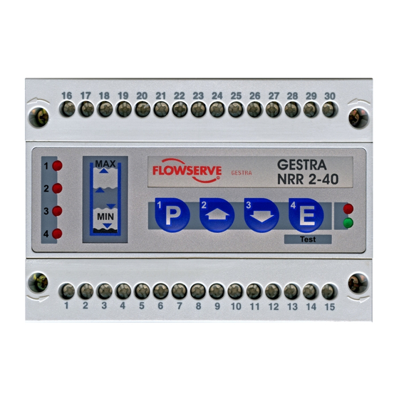
Functional Elements NRR 240 Fig. 4 Fig. 5... -
Page 12: Key
Design / Functional Elements / Installation Alarm Malfunction Status LED LED 1 Switchpoint 1 MAX alarm Multifunction LED 2 Closing control valve Not assigned Multifunction LED 3 Opening control valve Not assigned Multifunction LED 4 Switchpoint 4 MIN alarm Multifunction LED Bus status LED Power Enter / Test... -
Page 13: Example Of Installation
Installation – continued – Example of Installation Fig. 6 Fig. 7... -
Page 14: Electrical Connection
Electrical Connection Control cable NRS, NRR, LRR, TRS, URB 1 To wire the equipment, multicore twistedpair control cable must be used for the bus line, e. g. UNI TRONIC ® BUS CAN 2 x 2 x ... mm or RE2YCYVfl 2 x 2 x ... mm Control cable assemblies (2 x 2 x 0.32 mm²... -
Page 15: Note
If a safety power supply unit (e. g. SITOP smart, 24 V, 2.5 A) is used for the voltage supply of the CAN bus do not tap the supply voltage from the terminals 1 and 5 of the GESTRA control devices. -
Page 16: Wiring Diagram
Electrical Connection – continued – Wiring diagram Fig. 8 NRR 2-40 as 3-position stepping controller Fig. 9 1000 Ω Valve actuator... - Page 17 Electrical Connection – continued – Wiring diagram Fig. 10 NRR 2-40 as continuous controller...
-
Page 18: Key
Electrical Connection – continued – Mains supply MAX limit contact (MAX alarm) Activation control of valve actuator Fill control: = Valve CLOSED 23 = Valve OPEN 25 Discharge control: = Valve OPEN 23 = Valve CLOSED 25 MIN limit contact (MIN alarm) Actual value output 420 mA (optional) Controller output, analogue, manipulated variable Y, 420 mA Input for feedback potentiometer 1000 Ω... -
Page 19: Can Bus Wiring Diagram
Electrical Connection – continued – CAN bus wiring diagram URB 2 NRS, NRR, LRR, NRG, LRG, TRS, URB 1 EF, URZ RES 1 RES 2 Fig. 11 Attention Wire equipment in series. Startype wiring is not permitted! Link screens of control cables such that electrical continuity is ensured and connect them once to the central earthing point (CEP). -
Page 20: Note
The CAN address (node ID) can be set between 1 – 123. The equipment has already been configured at our works for operation with other GESTRA components and can be used straight away without having to set the node ID. -
Page 21: Node Id
Basic Settings – continued – Node ID Water level limiter NRS 140 NRG 1640 (1) NRG 1640 (2) Reserved Reserved X + 1 X + 2 X + 3 X + 4 Factory setting Safety system for steam boilers with superheater NRS 140.1 NRG 1640 (1) NRG 1640 (2) -
Page 22: Factory Setting
Basic Settings – continued – Factory setting The level controller features the following factory set default values: Baud rate: 250 kb/s Relay deenergizing delay, switchpoint 1: 1s : 20 % Relay deenergizing delay, switchpoint 4: 1s Proportional range X Node ID: 40 Relay deenergizing delay, switchpoint 1: 3s Switchpoint 1: 80 % Relay deenergizing delay, switchpoint 4: 3s... -
Page 23: Establishing / Changing Node Id
Basic Settings – continued – Establishing / changing node ID If several identical systems are to communicate in a CAN bus network, allocate a different node ID for each system (e. g. limiter, controller, etc). In most cases it is sufficient to commission the equipment with the default factory settings. -
Page 24: Dead Band
Basic Settings – continued – Dead band To prevent oscillation or repeated activationdeactivation cycles of the controlled system, a deadband can be defined for the septpoint “W”. The setpoint is defined by the proportional range which is limited by the switchpoints 2 and 3. To set the code switch 8 remove the terminal strip 9. - Page 25 To set the dead band refer to Fig. 16. Dead band in this example: 2 % Apply mains voltage. GESTRA NRR 2-40 The four status LEDs are flashing rapidly. If the LED “Power” is alight, the adjustment was successful. Test If the LED “Bus status”...
-
Page 26: Commissioning Procedure
When using the operating device URB ... all parameters can be set via its user interface. NRR 240 Apply mains voltage. GESTRA NRR 2-40 The four status LEDs are flashing rapidly. The LED “Power” is illuminated. The system test takes 2 seconds. - Page 27 Commissioning – continued – Setting measuring range – continued – Press button briefly. Attention: In the event of a system malfunction, the LED(s) “Bus status” and/or “Power” will be flashing rapidly when in program mode. Quit program mode and analyse the system malfunction (see pages 36 –...
-
Page 28: Switchpoints And Proportional Range
Commissioning – continued – Switchpoints and proportional range NRG 2640 Fig. 18 You can establish two switchpoints and the proportional band X within the control range. 80 % 90 % 70 % 20 % 50 % 45 % 10 % 35 % 20 % 10 %... -
Page 29: Establishing Switchpoints And Proportional Range
Commissioning – continued – Establishing switchpoints and proportional range Press button briefly. Raise or lower the liquid level in the vessel to the desired value. Use button if you first want to establish a different switchpoint or the proportional band. Press button briefly. - Page 30 Commissioning – continued – Establishing switchpoints and proportional range – continued – Press button briefly. Switchpoint 3 is now saved. Press button briefly. The upper limit of the proportional band X (switchpoint 2) is now selected. Press button briefly. Lower or raise the liquid level until switchpoint 2 within the control range is reached.
-
Page 31: Calibrating The Feedback Potentiometer Of An External Control Valve
Fig. 21 0 Ω Attention Ω For the GESTRA level controller NRR 240 a 1000 feedback potentiometer in an external control valve is required! If the terminals for the feedback potentiometer are not wired or the feedback potentiometer is defective the NRR 240 will work as twoposition controller! Use the control and display units URB 1 and URB 2 for semiautomatic calibration of... -
Page 32: Operation
Operation NRR 240 Normal operation, controller is working. The green LEDs 2 and 3 are flashing when the external control valve is being opened or closed. All LEDs go out once the setpoint is reached. The LED “Power” is illuminated. Test NRR 240 Press button... -
Page 33: Alarm
Alarm NRR 240 The are two alarm conditions: MAX alarm MIN alarm MAX alarm LED 1 is flashing rapidly. LED 1 is illuminated after the deenergizing flashing illuminated delay has been elapsed. MIN alarm LED 4 is flashing rapidly. flashing illuminated LED 4 is illuminated after the deenergizing delay has been elapsed. -
Page 34: Operational Malfunctions
Operational malfunctions Fault finding list for troubleshooting Equipment does not work – no function Fault: LED “Power ON” is not illuminated. Remedy: Switch on mains voltage. Wire equipment according to the wiring diagram. Equipment is not working – a malfunction is indicated Fault: In spite of correct wiring and commissioning of the equipment an error message is indicated. -
Page 35: System Malfunctions
System Malfunctions Danger The terminal strip of the equipment is live during operation. This presents the danger of electric shock! Cut off power supply before mounting or removing the terminal strips and the housing cover. NRR 240 Malfunctions occur if CAN bus components have been mounted, wired or configured incorrectly or if electronic component parts are defective, or in the event of excessive heat in the equipment or electrical interference in the supply system. -
Page 36: Danger
System malfunctions – continued – Danger The terminal strip of the equipment is live during operation. This presents the risk of severe cases of electric shock! Cut off power supply to the equipment before mounting or removing the terminal strips and the housing cover. Systematic malfunction analysis The sources of malfunctions occuring in CAN bus systems operating with several busbased stations must be analysed systematically since faulty components or incorrect settings can give rise to negative... -
Page 37: System Malfunction 1
System malfunction 1 LEDs 1 – 4 are flashing slowly. LEDs are flashing slowly GESTRA MIN / MAX alarm. NRR 2-40 Test Fault: The admissible temperature in the electrode terminal box is exceeded! Remedy: Insulate the electrode flange against thermal radiation. -
Page 38: System Malfunction 3
System malfunctions – continued – System malfunction 3 LED bus status is flashing slowly GESTRA NRR 2-40 Test LED is flashing slowly Fault: A malfunction in the CAN bus has occurred. Remedy: Restart system. LED bus status is flashing slowly... -
Page 39: System Malfunction 4
For details on the conformity of our equipment according to the European Directives see our Declaration of Conformity or our Declaration of Manufacturer. The current Declaration of Conformity / Declaration of Manufacturer are available in the Internet under www.gestra./de/documents or can be requested from us. - Page 40 Agencies all over the world: www.gestra.de GESTRA AG Münchener Straße 77 28215 Bremen Germany Telefon +49 421 35030 Telefax +49 421 3503393 Email info@de.gestra.com www.gestra.de 81036906/072017cm (80846008) · GESTRA AG · Bremen · Printed in Germany...
Need help?
Do you have a question about the NRR 2-40 and is the answer not in the manual?
Questions and answers