GESTRA NRR 2-50 Original Installation & Operating Manual
Hide thumbs
Also See for NRR 2-50:
- Installation instructions manual (28 pages) ,
- Original installation & operating manual (28 pages)

Related Manuals for GESTRA NRR 2-50


Summary of Contents for GESTRA NRR 2-50
- Page 1 Level Controller NRR 2-50 NRR 2-51 Original Installation & EN (USA) Operating Manual 850699-00 English...
-
Page 2: Table Of Contents
Output of manipulated variable Y or connection of actual value output (optional) ......23 In the plant: Electrically connecting the level transmitter ..............24 Connecting the level transmitter ....................24 NRR 2-50, NRR 2-51 - USA - Installation & Operating Manual - 850699-00... - Page 3 Indications, diagnosis and corrective action ................... 31 Important notes ..........................31 Action against high-frequency interference ..................31 Taking out of service .......................... 32 Disposal .............................. 32 UL components ........................... 32 NRR 2-50, NRR 2-51 - USA - Installation & Operating Manual - 850699-00...
-
Page 4: Content Of This Manual
Scope of supply, product package NRR 2-50 1 level controller NRR 2-50 1 Installation & Operating Manual NRR 2-51 1 level controller NRR 2-51 1 Installation & Operating Manual NRR 2-50, NRR 2-51 - USA - Installation & Operating Manual - 850699-00... -
Page 5: How To Use This Manual
How to use this Manual This Installation & Operating Manual describes the correct use of the NRR 2-50, NRR 2-51 level controller. It applies to persons who integrate this equipment in control systems, install, bring into service, operate, maintain and dispose of this equipment. Anyone carrying out the above-men- tioned activities must have read this Installation &... -
Page 6: Types Of Warning
CAUTION Warning of a situation that may result in minor or moderate injury. ATTENTION Warning of a situation that results in damage to property or the environment. NRR 2-50, NRR 2-51 - USA - Installation & Operating Manual - 850699-00... -
Page 7: Specialist Terms, Abbreviations
A boiler that is operated at 145 psi (10 bar) and 356 °F (180 °C) may be designed to withstand a pressure of 870 psi (60 bar) and a temperature of 527 °F (275 °C), for example, which is therefore not necessarily its operating point. NRR 2-50, NRR 2-51 - USA - Installation & Operating Manual - 850699-00... -
Page 8: Usage For The Intended Purpose
The NRR 2-50 and NRR 2-51 are classified as operating controls in accordance with UL 60730-1. When used as intended, the NRR 2-50, NRR 2-51 level controller can be combined in a circuit with an NRGT 26-2 level transmitter. -
Page 9: Basic Safety Information
Check that the plant is not carrying live voltage before commencing work. ■ Attempts to repair the equipment will cause the plant to become unsafe. The NRR 2-50, NRR 2-51 level controller may only be repaired by the manufacturer, ■ GESTRA AG. -
Page 10: Required Personnel Qualifications
Persons trained by the plant operator to work Refits Specialist staff with pressure and temperature. Notes on product liability The manufacturer cannot accept any liability for damages resulting from improper use of the equipment. NRR 2-50, NRR 2-51 - USA - Installation & Operating Manual - 850699-00... -
Page 11: Function
7-segment LED display. In the event of a malfunction, the MIN and MAX alarm is triggered. If faults occur only in the NRR 2-50, NRR 2-51 level controller, the MIN and MAX alarm is triggered and the system is restarted. -
Page 12: Technical Data
1 analog input 4-20 mA, e.g., for the NRGT 26-2 level transmitter, 2-pole with shield. Outputs: NRR 2-50: 2 volt-free relay contacts, 8 A 250 V AC / 30 V DC cos ϕ = 1 (control valve open/closed). 1 volt-free relay contact, 8 A 250 V AC / 30 V DC cos ϕ = 1. - Page 13 24 hours. Storage temperature -4 ° … 158 °F (-20 ° … +70 °C), only switch on after a defrosting period of 24 hours. Relative humidity Max. 95%, non-condensing NRR 2-50, NRR 2-51 - USA - Installation & Operating Manual - 850699-00...
-
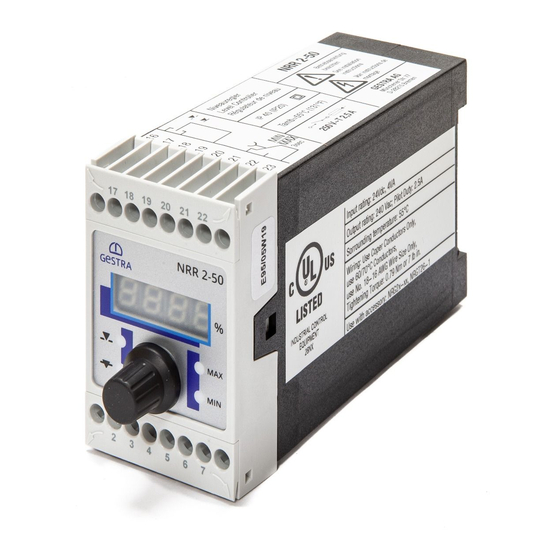
Page 14: Rating Plate, Identification
Tightening: Torque 0.79Nm or 7lb in. Tightening: Torque 0.79Nm or 7lb in. Use with accessory: NRGT 26-2 Use with accessory: NRGT 26-2 Fig. 2 NRR 2-50 NRR 2-51 NRR 2-50, NRR 2-51 - USA - Installation & Operating Manual - 850699-00... -
Page 15: Factory Default Settings
Fill control function ■ Code switch MIN/MAX output contact set as MAX alarm : S1, S2, S3, S4 OFF ■ Code switch : S1, S2, S3, S4 OFF NRR 2-50, NRR 2-51 - USA - Installation & Operating Manual - 850699-00... -
Page 16: Changing The Factory Default Settings
Detach the terminal strip. ■ Fig. 3 When your changes are complete: Insert the terminal strip. ■ Switch the supply voltage back on. The equipment restarts ■ NRR 2-50, NRR 2-51 - USA - Installation & Operating Manual - 850699-00... - Page 17 To do this, please pay attention to the NRGT 26-2 Installation & Operating Manual. Do not move switch S4 on code switch NRR 2-50, NRR 2-51 - USA - Installation & Operating Manual - 850699-00...
-
Page 18: Dimensions Of The Nrr 2-50, 2-51
0.6 in (15 mm) 1.81 in (46 mm) 4.72 in (120 mm) Fig. 5 Upper terminal strip Terminal box Lower terminal strip Support rail TH 35, EN 60715 NRR 2-50, NRR 2-51 - USA - Installation & Operating Manual - 850699-00... -
Page 19: Preparing For Installation
Take further measures to protect the equipment from lightning, insects and ■ animals, and salty air. You will need the following tools: Screwdriver size 1/8 inch (3.2 mm) ■ NRR 2-50, NRR 2-51 - USA - Installation & Operating Manual - 850699-00... -
Page 20: Installation
Installation Installing in the control cabinet The NRR 2-50, NRR 2-51 level controller is clipped onto a type TH 35, EN 60715 support rail in the control cabinet. Fig. 5 4 NRR 2-50, NRR 2-51 - USA - Installation & Operating Manual - 850699-00... -
Page 21: In The Control Cabinet: Electrically Connecting The Level Controller
Max. 3 NRS/NRR 2-5.. units can be connected (series connection). Central grounding point (CGP) in control cabinet Output contact for control valve actuation MIN/MAX output contact, off delay 3 seconds Actual value output 4-20 mA (optional) NRR 2-50, NRR 2-51 - USA - Installation & Operating Manual - 850699-00... -
Page 22: Wiring Diagram For Level Controller Nrr 2-51
Max. 3 NRS/NRR 2-5.. units can be connected (series connection). Central grounding point (CGP) in control cabinet MIN output contact, off delay 3 seconds MAX output contact, off delay 3 seconds Output 4-20 mA, manipulated variable Y NRR 2-50, NRR 2-51 - USA - Installation & Operating Manual - 850699-00... -
Page 23: Connecting The Supply Voltage
UL 60730-1 between the current loop and live parts of the equipment that are not supplied with safety extra-low voltage (SELV). Attention Do not use unused terminals as support terminals. ■ NRR 2-50, NRR 2-51 - USA - Installation & Operating Manual - 850699-00... -
Page 24: In The Plant: Electrically Connecting The Level Transmitter
Electrically connecting the level transmitter Connecting the level transmitter When used as intended, the NRR 2-50, NRR 2-51 level controller can be combined in a circuit with the NRGT 26-2 level transmitter. Please use a shielded, multi-core TC-ER control cable with minimum wire size AWG18, e.g., OELFLEX CONTROL TM CY 5G1, to connect the equipment. -
Page 25: Meaning Of Codes On The 7-Segment Display
Indicated in the event of errors E.005 Error Faulty level electrode/transmitter, measuring voltage/current too low E.006 Error Faulty level electrode/transmitter, measuring voltage/current too high E.013 Error MIN switchpoint higher than MAX switchpoint NRR 2-50, NRR 2-51 - USA - Installation & Operating Manual - 850699-00... -
Page 26: Setting The Measuring Range (On The Nrgt 26-2)
(32 mm)] or in the range from 5.04 in (128 mm) to 7.56 in (192 mm). Larger Slow correction of deviations Reacts slowly Integral action Fast correction of deviations, time Smaller Reacts quickly control loop may tend to overshoot NRR 2-50, NRR 2-51 - USA - Installation & Operating Manual - 850699-00... -
Page 27: Bringing Into Service
Turn the rotary knob until the next parameter is shown. Or turn the rotary knob until the actual value is displayed. Or after 30 s, the actual value is displayed automatically. NRR 2-50, NRR 2-51 - USA - Installation & Operating Manual - 850699-00... -
Page 28: Operation, Alarm And Test
Select parameter tt, enter and save the desired The valve travel time is set between 10-600 s. time. Note The NRR 2-50 level controller is only equipped with one output contact for limit ■ signaling. Therefore, please define its function (MAX or MIN alarm) using code switch . -
Page 29: Level Controller Nrr 2-50 Indications
MAX LED flashes red Off delay in progress. MAX water level switchpoint reached or Delay time elapsed, MAX output contacts 21/23 MAX LED lights up red exceeded. closed, 22/23 open. NRR 2-50, NRR 2-51 - USA - Installation & Operating Manual - 850699-00... -
Page 30: Checking The Function Of The Min/Max Output Contacts
Turn the rotary knob until the actual value is displayed. Or after 30 s, the actual value is displayed automatically. Note The actual value is shown on the 7-segment display. NRR 2-50, NRR 2-51 - USA - Installation & Operating Manual - 850699-00... -
Page 31: Fault Indications And Troubleshooting
Increase the distance from sources of interference. ■ Check the connection of the shield to the central grounding point (CGP) in the control cabinet. ■ Suppress HF interference using hinged-shell ferrite rings. ■ NRR 2-50, NRR 2-51 - USA - Installation & Operating Manual - 850699-00... -
Page 32: Taking Out Of Service
Fig. 9 Disposal Dispose of the equipment in accordance with statutory waste disposal regulations. UL components NRR 2-50 and NRR 2-51 level controllers are registered under XACN.E513189. NRR 2-50, NRR 2-51 - USA - Installation & Operating Manual - 850699-00... - Page 33 For your notes NRR 2-50, NRR 2-51 - USA - Installation & Operating Manual - 850699-00...
- Page 34 For your notes NRR 2-50, NRR 2-51 - USA - Installation & Operating Manual - 850699-00...
- Page 35 For your notes NRR 2-50, NRR 2-51 - USA - Installation & Operating Manual - 850699-00...
- Page 36 You can find our authorized agents around the world at: www.gestra.com GESTRA AG Münchener Straße 77 28215 Bremen Germany Tel. +49 421 3503 0 +49 421 3503 393 e-mail info@de.gestra.com www.gestra.com 850699-00/08-2021cm (809148-00) · GESTRA AG · Bremen...
Need help?
Do you have a question about the NRR 2-50 and is the answer not in the manual?
Questions and answers