
Related Manuals for GESTRA NRS 1-40


Summary of Contents for GESTRA NRS 1-40
- Page 1 Switching Controller NRS 140 Original Installation Instructions 81063507 E n g l i s h...
-
Page 2: Table Of Contents
Contents Page Important Notes Usage for the intended purpose ......................5 Safety note ............................. 5 Danger ..............................5 Attention ..............................5 ATEX (Atmosphère Explosible) .........................5 Note on the Declaration of Conformity / Declaration by the Manufacturer ...........5 Explanatory Notes Scope of supply ............................6 Description .............................6 Function ............................. - Page 3 Contents – continued – Page Electrical Connection Control cable ............................16 Note ..............................17 CAN bus voltage supply ........................17 Attention ..............................17 Wiring diagram .............................18 Attention ..............................18 Assignment diagram for sensorconnector union ..................19 Key ...............................19 CAN bus wiring diagram ........................20 Attention ...............................20 Note ..............................
- Page 4 Contents – continued – Page Emergency Operation Danger ..............................27 Emergency operation of waterlevel limiting system................27 Attention ...............................27 Malfunctions Danger ..............................28 Fault finding list for troubleshooting ......................28 System Malfunctions Danger ..............................29 NRS 140..............................29 Danger ..............................30 Systematic malfunction analysis ......................30 Error message 1 ...........................31 Error message 2 ...........................32 Error message 3 ..........................
-
Page 5: Important Notes
Important Notes Usage for the intended purpose Use switching controller NRS 140 only in conjunction with GESTRA level electrodes NRG 1640, NRG 1740, NRG 1940 or NRG 11140 for signalling lowwater level (min. alarm). Safety note The equipment must only be installed and commissioned by qualified and adequately trained personnel. -
Page 6: Explanatory Notes
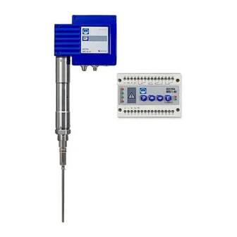
Explanatory Notes Scope of supply NRS 140 1 Switching controller NRS 140 (plugin unit in plastic case with terminals) 1 Terminating resistor 120 Ω 1 Installation and service manual Description The controller type NRS 140 is a selfmonitoring lowwater level limiter with periodic selfchecking and monitoring feature of the output relay contacts, to be used in conjunction with one level electrode type NRG 1640, 1740, 1940 or NRG 11140. -
Page 7: System Components
Explanatory Notes – continued – Function – continued – The automatic selftesting routine checks the switching controller every 3 seconds and the sensors (e.g. the level electrodes) every 10 seconds. During each selftesting routine the error messages will be stored in the switching controller. The error messages remain stored until the cause of the fault(s) is eliminated. -
Page 8: Technical Data
Technical Data NRS 140 Type approval no. TÜV · SWB/SHWS · 07403 EG BAFMUC 02 02 103881 002 Input / Output Interface for CAN bus to ISO 11898 CANopen protocol Output voltage supply for electrodes 18 – 36 V, shortcircuit protected Output for protection circuit Two voltfree relay contacts, locally connected in series. -
Page 9: Name Plate / Marking
Technical Data – continued – Name plate / marking NRS 1-40 Steuergerät Betriebsanleitung control device beachten appareille de commande See installation Node ID:___ ___ ___ instructions Voir instructions de montage 230V -15/+10% 10VA IP 40 (IP20) Alarm IN / OUT: CAN-Bus Tamb = 55 °C ( 131 °F) -
Page 10: Dimensions
Technical Data – continued – Dimensions Fig. 2... -
Page 11: Design
Design NRS 140 " Fig. 3... -
Page 12: Functional Elements
Functional Elements NRS 140 Fig. 4 Fig. 5... -
Page 13: Key
Design / Functional Elements – continued – Indicator LED Alarm Malfunction LED 1: Electrode 1 Lowlevel alarm Malfunction message LED 1: Electrode 2 Lowlevel alarm Malfunction message LED 3 No function Malfunction message LED 4 No function Malfunction message LED “Bus status” LED “Power”... -
Page 14: Installation
1. Clip switching controller onto mounting rail 35 x 15 mm (DIN EN 50022): 2. Align switching controller, see Fig. 7 Note If an external measuring pot is used, each level electrode type NRG 1...40 requires one switching controller NRS 140 and one GESTRA monitoring unit SRL 640. Tools Screwdriver (5.5/100) -
Page 15: Example Of Installation
Installation – continued – Example of installation " § Fig. 6 Fig. 7... -
Page 16: Key
Installation – continued – Terminal strips Screws for terminal strip " Enclosure § Mounting rail TS 35 x 15 DIN EN 50022 Electrical Connection Control cable NRS, NRR, LRR, TRS, URB 1 Note that screened multicore twistedpair control cable is required for the BUS line, e.g. UNITRONIC ®... -
Page 17: Note
If a safety power supply unit (e.g. SITOP smart, 24 V, 2.5 A) is used for the voltage supply of the CAN bus do not tap the supply voltage from the terminals 1 and 5 of the GESTRA control devices. -
Page 18: Wiring Diagram
Electrical Connection – continued – Wiring diagram & 17 18 19 20 21 22 23 24 GESTRA NRS 1-40 Test 11 12 18V-36V DC 120 Ω CAN-Bus Fig. 8 Attention NRS 140 is the first device in the safety circuit. -
Page 19: Assignment Diagram For SensorConnector Union
Electrical Connection – continued – Assignment diagram for sensorconnector union 120 Ω 120 Ω Fig. 9 Fig. 10 Fig. 11 RES 1 RES 2 Mains voltage Safety circuit, uninterrupted, ≥ 18 V AC/DC & Further devices in the safety circuit Photo MOS output 24 V –... -
Page 20: Can Bus Wiring Diagram
Electrical Connection – continued – CAN bus wiring diagram URB 2 NRS, NRR, LRR, NRG, LRG, CEP*) TRS, URB 1 EF, URZ RES 1 RES 2 *) Central Earthing Point Fig. 12 Attention Wire equipment in series. Startype wiring is not permitted. Interlink screens of control cables such that electrical continuity is ensured and connect them once to the central earthing point (CEP). -
Page 21: Note
The fourcore bus cable serves as power supply and data highway for highspeed data exchange. The CAN address (Node ID) can be set between 1 and 99. The NRS 140 is configured at our works and ready for service with other GESTRA system components without having to set the node ID. -
Page 22: Node Id
Basic Settings – continued – Node ID Lowlevel limiter NRS 140 NRG 1640 (1) NRG 1640 (2) Reserved Reserved X + 1 X + 2 X + 3 X + 4 Factory setting Safety system for steam boilers with superheater NRS 140.1 NRG 1640 (1) NRG 1640 (2) -
Page 23: Note
Basic Settings – continued – Note The node ID “3” for the second level electrode NRG 1...40 must be set on site, because the level electrode NRG 1...40 features the default factory setting node ID “2” when supplied. Note that a wire link on the electronic circuit board of the second level electrode NRG 1...40 must also be repositional. -
Page 24: Code Switch Settings
Basic Settings – continued – Code switch settings NRG... NRG... 1 + 2 Fig. 13 Fig. 14 Node ID Node ID Fig. 15 (Factory setting) Fig. 16 (Example) Baud rate Cable length 250 kBit/s 125 m 125 kBit/s 250 m 100 kBit/s 335 m 50 kBit/s... -
Page 25: Commissioning
Commissioning NRS 140 Apply power to the unit. The four indicator LEDs flash rapidly. The LED “Power” lights up. The test cycle takes about 3 sec. Note To analyse and eliminate malfunctions that may occur during the com missioning procedure refer to section “Malfunctions” and “System Malfunctions”. Operation NRS 140 Normal operation, electrode(s) submerged. -
Page 26: Alarm
Test Cycle – continued – NRS 140 – continued – Press button briefly (1 sec.). LED 2 flashes rapidly and remains permanently illuminated after 3 s. A lowlevel alarm is simulated for electrode 2. This test cycle is performed for the waterlevel limiting system (two level electrodes). -
Page 27: Emergency Operation
Emergency Operation Danger The terminal strip of the NRS 140 is live during operation. This presents the danger of electric shock. Cut off power supply before mounting or removing the terminal strips or the housing cover. Emergency operation of waterlevel limiting system If one level electrode fails to operate the system can continue to operate in emergency mode under constant supervision according to TRD 401 with one level electrode: 1. -
Page 28: Malfunctions
Malfunctions Danger The terminal strip of the NRS 140 is live during operation. This presents the danger of electric shock. Cut off power supply before mounting or removing the terminal strips or the housing cover. Fault finding list for troubleshooting Water level below switchpoint LOW LEVEL –... -
Page 29: System Malfunctions
System Malfunctions Danger The terminal strip of the NRS 140 is live during operation. This presents the danger of electric shock. Cut off power supply before mounting or removing the terminal strips or the housing cover. NRS 140 Faulty installation and/or configuration of CAN bus components, excessive temperatures in the devices, defective electronic component parts or electromagnetic interferences of the supply system can result in system malfunctions. -
Page 30: Danger
System Malfunctions – continued – Danger The terminal strip of the NRS 140 is live during operation. This presents the danger of electric shock. Cut off power supply before mounting or removing the terminal strips or the housing cover. Systematic malfunction analysis The sources of malfunctions occurring in CAN bus systems operating with several busbased stations must be analysed systematically since faulty components or incorrect settings can give rise to nega tive interactions with intact bus devices in the CAN bus system. -
Page 31: Error Message 1
System Malfunctions – continued – Error message 1 LED 1 is flashing slowly. A system malfunction in level electrode 1 was detected. Hold down button LED 1 and 2 are flashing slowly. Fault: The max. admissible temperature in the terminal box of the electrode has been exceeded. -
Page 32: Error Message 2
System Malfunctions – continued – Error message 2 LED 2 is flashing slowly. A system malfunction in level electrode 2 was detected. Hold down button LED 1 and 2 are flashing slowly. Fault: The max. admissible temperature in the terminal box of the electrode has been exceeded. - Page 33 System Malfunctions – continued – Error message 3 LED 3 is flashing slowly. A malfunction in the bus communication between level switch and level electrode 1 has been detected. Hold down button LED 1 is flashing rapidly. Fault: Bus lines C and C are interchanged.
- Page 34 System Malfunctions – continued – Error message 3 – continued – Hold down button LED 2 flashes rapidly. Fault : Bus lines C and C are interchanged. Remedy: Connect bus lines according to the wiring diagram. Fault: The operating mode setting is not correct: Water level limiter (one level electrode) or water level limiting system (two electrodes).
-
Page 35: Error Message 3
System Malfunctions – continued – Error message 4 LED 4 is flashing slowly. A malfunction in the level switch has been detected. Fault: No voltage or pulsetriggered voltage across terminal 25, selfchecking routine unsuccessful. Remedy: Wire NRS 140 as first device in the safety chain. Wire NRS 140 according to wiring diagram (ensure constant voltage supply across terminal 25). -
Page 36: Error Message 6
– continued – Error message 6 LEDs 1 to 4 are flashing slowly and/or GESTRA LED “Bus status” is flashing slowly. NRS 1-40 Test Fault: Data transfer between switching controller and electrode interrupted. Remedy: The bus cables have to be connected correctly according to the wiring diagram (observe polarity!). -
Page 37: Decommissioning
Decommissioning Danger The terminal strip of the equipment is live during operation. This presents the danger of electric shock. Cut off power supply before mounting or removing the terminal strip and the housing cover. Disposal Remove the equipment and separate the waste materials in accordance with the material specification. - Page 38 For your notes...
- Page 39 For your notes...
- Page 40 Agencies all over the world: www.gestra.de GESTRA AG Münchener Straße 77 28215 Bremen Germany Telefon +49 421 35030 Telefax +49 421 3503393 Email info@de.gestra.com www.gestra.de 81063507/052017csa (80850008) · GESTRA AG · Bremen · Printed in Germany...
Need help?
Do you have a question about the NRS 1-40 and is the answer not in the manual?
Questions and answers