GESTRA NRR 2-50 Installation Instructions Manual
Hide thumbs
Also See for NRR 2-50:
- Original installation & operating manual (36 pages) ,
- Original installation & operating manual (28 pages)

Subscribe to Our Youtube Channel
Related Manuals for GESTRA NRR 2-50


Summary of Contents for GESTRA NRR 2-50
- Page 1 Level Controller NRR 2-50 NRR 2-51 Original Installation Instructions 819180-03 E n g l i s h...
-
Page 2: Table Of Contents
Technical data NRS 2-50 / NRR 2-51 ..........................6 Contents of package ..........................7 In the control cabinet: Installing the level controller Dimensions of the NRR 2-50 / NRR 2-51 ....................8 Key .................................8 Installation in control cabinet ........................8 Name plate/identification ........................9 In the control cabinet: Electrically connecting the level controller Wiring diagram for level controller NRR 2-50 ..................10... - Page 3 Setting parameters..........................18 Setting the measuring range .........................19 Operation, alarm and testing Setting switchpoints and control parameters ..................20 Level controller NRR 2-50 Displays ....................21 Level controller NRR 2-51 Displays ....................21 Check function of MIN/MAX output contacts ..................22 Fault indications and troubleshooting Display, diagnosis and troubleshooting ....................23...
-
Page 4: Important Notes
7-segment LED display. In the event of a malfunction, the MIN and MAX alarm is triggered. If faults occur only in the NRR 2-50 / NRR 2-51 level controller, the MIN and MAX alarm is triggered and the system is restarted. -
Page 5: Safety Information
Directives and standards VdTÜV Bulletin "Wasserstand 100" (Water Level 100) The NRR 2-50 / NRR 2-51 level controller, in combination with the NRG 2.-.. level electrode and the NRGT 26-1 level transmitter, is type approved to the VdTÜV Bulletin "Water Level 100". -
Page 6: Technical Data
12 VDC Outputs: NRR 2-50: 2 floating changeover contacts, 8 A 250 V AC / 30 V DC cos ϕ = 1 (control valve open/closed). 1 floating changeover contact, 8 A 250 V AC / 30 V DC cos ϕ = 1. -
Page 7: Contents Of Package
Type approval no.: TÜV · WR · XX-425 (see name plate) Contents of package NRR 2-50 1 level controller NRR 2-50 1 installation & operating manual NRR 2-51 1 level controller NRR 2-51 1 installation & operating manual... -
Page 8: In The Control Cabinet: Installing The Level Controller
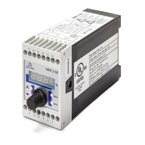
Housing Lower terminal strip Support rail TH 35, EN 60715 Installation in control cabinet The NRR 2-50 / NRR 2-51 level controller is clipped onto a type TH 35, EN 60715 support rail in the control cabinet. Fig. 1 4... -
Page 9: Name Plate/Identification
In the control cabinet: Installing the level controller continued Name plate/identification Name plate NRR 2-50, top Name plate NRR 2-51, top Safety information Type Manufacturer designation Degree of protection External fuse for output contacts Ambient temperature Output contacts Name plate, bottom... -
Page 10: In The Control Cabinet: Electrically Connecting The Level Controller
In the control cabinet: Electrically connecting the level controller Wiring diagram for level controller NRR 2-50 NRR 2-50 MIN/MAX MIN/MAX 0.5 A 0.5 A (semi- (semi- delay) delay) Fig. 3 Supply voltage connection 24 V DC with semi-delay fuse 0.5 A provided on site Level electrode NRG 21-.. -
Page 11: Wiring Diagram For Level Controller Nrr 2-51
In the control cabinet: Electrically connecting the level controller continued Wiring diagram for level controller NRR 2-51 NRR 2-51 0.5 A 0.5 A (semi- (semi- delay) delay) Fig. 4 Supply voltage connection 24 V DC with semi-delay fuse 0.5 A provided on site Level electrode NRG 21-.. -
Page 12: Supply Voltage Connection
In the control cabinet: Electrically connecting the level controller continued Supply voltage connection The equipment is supplied with 24 V DC and has an external semi-delay 0.5 A fuse. Please use a safety power supply unit with safe electrical isolation. This power supply unit must be electrically isolated from dangerous live voltages and meet the require- ments for double or reinforced insulation in accordance with one of the following standards: DIN EN 50178, DIN EN 61010-1, DIN EN 60730-1 or DIN EN 60950. -
Page 13: In The System
Electrically connecting the level electrode/transmitter Connection of level electrode/level transmitter The NRR 2-50 / NRR 2-51 level controller can be combined with the NRG 21-.. or NRG 26-21 level electrodes and the NRGT 26-1 level transmitter. For connecting the equipment, please use a screened, multi-core control cable with a minimum conductor size of 0.5 mm... -
Page 14: Changing Factory Settings
Changing factory settings Danger The upper terminal strip of the equipment is live during operation. There is a risk of serious injury due to electric shock! Always cut off the power supply to the equipment before installing, removing or connecting the terminal strip! Changing the function and input of the level electrode/transmitter The input and function are determined by the setting of code switch To make changes, you can access the code switch as follows:... - Page 15 Toggle switch, white Level controller NRR 2-50 Output contact set for MAX alarm Output contact set for MIN alarm Level controller NRR 2-50 / NRR 2-51 Input for connection of level electrode NRG 21-.. or NRG 26-21 Input for connection of level...
-
Page 16: Operating The Level Controller
Setpoint Setpoint Proportional band adjustable between 0 and 100 % Time integral Integral action time, adjustable between 0 and 100 seconds Valve travel time (NRR 2-50 only), adjustable Motor travel time between 10 and 600 seconds tESt Test Tests output relays CAL.L... -
Page 17: Setting The Measuring Range
Operating the level controller continued Setting the measuring range Lower end of measuring range, adjustable NRG 2.-.. Upper end of measuring range, adjustable NRGT 26-1 Measuring range [mm] = xxx % Inactive range Maximum installed length at 238 °C Set the lower and upper ends of the measur- ing range for your fill level measurement. -
Page 18: Commissioning
Commissioning Setting parameters OO75 OO75 7-segment display Amber MAX LED Valve opens Rotary knob Valve MIN LED with closes integrated push-button Fig. 7 Start Action Display Function 7-segment display shows software and equipment System test, takes approx. 3 sec. Switch on supply voltage. version Water level between MIN and MAX. -
Page 19: Setting The Measuring Range
Commissioning continued Setting the measuring range Level electrode NRG 2.-.. only : Setting the measuring range, option 1 Action Display Function Reduce water level until start of measuring range A. After a short time, a hexadecimal number Calibrate start Select parameter CAL.L. flashes. -
Page 20: Operation, Alarm And Testing
Integral action time settings between 10-600 s. percentage. Note The NRR 2-50 level controller is only equipped with one output contact for limit indications. Therefore, please define its function (MAX or MIN alarm) using the code switch . Fig. 5, 6. -
Page 21: Level Controller Nrr 2-50 Displays
Operation, alarm and testing continued Level controller NRR 2-50 Displays Operation Action Display Function Valve output contact 16/17/19 open. MIN output contacts 16/18 open, Valve and MIN/ MAX LEDs do Actual value = setpoint 17/18 closed. not light up MAX output contacts 21/23 open, 22/23 closed. -
Page 22: Check Function Of Min/Max Output Contacts
Operation, alarm and testing continued Check function of MIN/MAX output contacts Test of MIN alarm and MAX alarm Action Display Function MAX LED flashes red De-energizing delay in progress. MAX LED lights up red for 3 MAX output contact 21/23 closed, 22/23 open. In operating mode: seconds Water level between MIN... -
Page 23: Fault Indications And Troubleshooting
Fault indications and troubleshooting Display, diagnosis and troubleshooting Important Please check the following before fault diagnosis: Supply voltage: Is the level switch supplied with the voltage specified on the name plate? Wiring: Does the wiring conform to the wiring diagram? Faults indicated by the 7-segment display Fault code Fault... -
Page 24: Further Information
Further information Action against high-frequency interference High-frequency interference can be caused by out-of-phase switching operations. If such interference occurs and results in sporadic failure, we recommend taking the following action to suppress interfer- ence: Provide inductive loads with RC combinations as per manufacturer's specifications. Route the connecting cable to the level electrode or level transmitter separately from power lines. - Page 25 For your notes...
- Page 26 For your notes...
- Page 27 For your notes...
- Page 28 Agencies all over the world: www.gestra.de GESTRA AG Münchener Straße 77 28215 Bremen Germany Telefon +49 421 3503-0 Telefax +49 421 3503-393 E-mail info@de.gestra.com www.gestra.de 819180-03/03-2017cm (808863-03) · GESTRA AG · Bremen · Printed in Germany...
Need help?
Do you have a question about the NRR 2-50 and is the answer not in the manual?
Questions and answers