Table of Contents
Advertisement
Quick Links
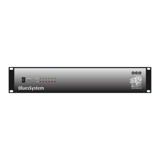
BluesSystem
Installation Manual
Manuel d'installation
This product is intended for professional use only.
Read this entire document before using this product.
Copyright © 2016 Electronic Theatre Controls, Inc.
All rights reserved. Product information and specifications subject to change.
Part Number: 7492M2100 Rev: C
Released: 2016-03
Advertisement
Table of Contents

Subscribe to Our Youtube Channel
Related Manuals for ETC GDS BluesSystem


Summary of Contents for ETC GDS BluesSystem
- Page 1 BluesSystem Installation Manual Manuel d’installation This product is intended for professional use only. Read this entire document before using this product. Copyright © 2016 Electronic Theatre Controls, Inc. All rights reserved. Product information and specifications subject to change. Part Number: 7492M2100 Rev: C Released: 2016-03...
- Page 2 ® ET C i s a r eg i s t er ed tr ad e ma rk o f El e c t ro n i c T h ea t re C on t r ol s , I n c . i n t h e U n i t e d S t a t e s a n d o t h e r c o u n t r i e s .
-
Page 3: Table Of Contents
Introduction ......1 Help from ETC Technical Services......2 Safety . -
Page 4: Introduction
RISK OF ELECTRIC SHOCK! This warning statement indicates situations where there is a risk of electric shock. ETC's user documents are designed for printed or electronic use. However, there are many advantages to using the electronic (.PDF) versions. In addition to the benefits of a PDF, such as word search, bookmarks, and commenting tools, you can click on headings in the Table of Contents and jump to the desired page. -
Page 5: Help From Etc Technical Services
If you are having difficulties, your most convenient resources are the references given in this document. To search more widely, try the ETC website at www.etcconnect.com. If none of these resources are sufficient, contact ETC Technical Services directly at one of the offices identified below. -
Page 6: System Overview
System Overview BluesSystem is comprised of BlueDome or BlueBeam fixtures and a One-Zone or Six-Zone LV Power Supply. The fixtures mount directly to a junction box (either flush or surface mounted are acceptable, but not provided) and provide focused light for corridor, stairway, lobby, and backstage applications. -
Page 7: Fixtures
BlueBeam and BlueDome LED lighting fixtures mount directly to a standard metal or plastic conduit junction box (either flush mounted or surface mount is acceptable). A compatible junction box cover plate is available from ETC in either square, round, or octagonal. Contact ETC Customer Service for ordering information. - Page 8 Accessories The BlueBeam low-voltage LED lighting fixture provides directional blue light and is available in 2.5, 5, 10, 20, and 50 degree variants. The beam can be masked by using a cowl accessory. The cowl can be rotated to mask off a selected side of the fixture beam. Cowl Accessory The BlueDome low-voltage LED lighting fixture provides omnidirectional blue light at low levels and is available in frosted or opaque variants.
-
Page 9: Power Supplies
Power Supplies Overview The BluesSystem Power Supply provides power for the BlueDome and BlueBeam low-voltage LED lights. Power supplies are available in a One-Zone and Six-Zone variants. The One-Zone LV Power Supply provides power for up to 10 BlueBeam and BlueDome running lights and is wall mounted. - Page 10 Power Supply Electrical Specification One-Zone LV Power Supply • Input voltage/frequency - 100-240 VAC / 50-60 Hz • Maximum input current - 0.65A • Nominal output voltage - 24 VDC • Maximum output current - 1.6A Six-Zone LV Power Supply •...
-
Page 11: System Installation
• Always use the supplied gasket. • Do not allow moisture into rear terminal area. ETC recommends that you install all wiring in grounded metal conduit. When calculating cable sizes, each fixture consumes 0.13A at 24 VDC or 0.8A at 36V. -
Page 12: Supplies
Supplies The following supplies are included: • (1) Junction box cover plate (available in round, square, or octagonal) • (2) M4 screws for mounting the fixture to the junction box • (1) Sealing gasket • Wiring pigtail for power, ground, and control The following supplies are not included (provided by others): •... -
Page 13: Terminate Wiring
Terminate Wiring Wire terminations are made to the terminals located on the back side of the fixture. Note: It is acceptable to continue the wiring run for up to 10 fixtures per zone on a power supply. Step 1: Locate the provided fixture termination kit. Step 2: Connect ground. -
Page 14: Maximum Cable Length Charts
Step 4: Connect control. a: Locate the pre-stripped violet wire inside of the termination kit. b: Loosen but do not remove the CTRL terminal screw on the back of the fixture. c: Insert the spade terminal under the screw and tighten the screw firmly to secure. d: Locate a 3 position WAGO inside the termination kit and open all terminal levers. -
Page 15: Accessory Installation
Accessory Installation BluesSystem provides the cowl and the eyelid accessory options for masking unwanted light on the BlueBeam and the BlueDome low-voltage LED fixtures. Both accessories come with a provided plastic accessory ring that allows the cowl or eyelid to snap onto the fixture. Step 1: To install cowl and eyelid accessories, remove screws from the fixture. -
Page 16: Power Supplies
Power Supplies WARNING: A system without an accessible power disconnect device cannot be serviced or operated safely. Follow all local codes and restrictions. BluesSystem Power Supplies are available in a One-Zone and a Six-Zone variant and provide low voltage 24 or 36 VDC power to connected BlueBeam and BlueDome lighting fixtures. Model Description Notes... -
Page 17: Wall Mount Installation
Wall Mount Installation Four mounting holes are provided on the rear panel of the power supply and provide for easy mounting options.The power supply can be mounted to a wall or other smooth, supported, vertical surface. Step 1: Each non-vented edge of the power supply offers conduit knock outs. Knock out the required holes based on your installation wire plan. - Page 18 Low Voltage Outputs Power supply outputs (also known as Zones) can control a maximum of 10 BlueBeam or BlueDome fixtures installed in a single wire run. OUTPUT 1 OUTPUT 2 Cable Specification Output Wire Torque Notes Terminals Power Supports up to 10 fixtures per output.
- Page 19 Strip 7” (17.8cm) of the outer jacket off. Step 3: Label the cable with the data type and run designation. (DMX1, DMX2, etc.) Step 4: Strip the foil shielding from each wire set back to within 1/4” (6.3mm) of the outer jacket.
- Page 20 Terminate DMX In Step 1: Insert the Ground (Common) wire into the Ground terminal on the DMX In connector and tighten the screw firmly onto the wire. Step 2: Insert the Data - wire into the Data - terminal on the DMX In connector and tighten the screw firmly onto the wire.
- Page 21 Terminate Remote Switch Wiring REMOTE SWITCH Note: Switched connection requires a dry contact such as a switch or relay. Wires with voltage present should not be landed here. One-Zone LV Power Supply Step 1: Insert the wire from one side of the dry contact into terminal 1 and tighten the screw firmly onto the wire.
- Page 22 Terminate 0-10 VDC Wiring CAUTION: Control wires are polarity dependent. Crossing the + and – wires while combining drivers will result in improper performance. For Sink Control Note: Sink control refers to control voltage being provided by the BluesSystem Power Supply to the 0-10VDC controller to set the light output.
-
Page 23: Dimming Module
Dimming Module The BS-DM1 Dimmer Module is designed to allow intensity control of the BlueDome or BlueBeam light Fittings. The Dimmer Module can be fitted anywhere in series with the BlueDome or BlueBeam fixtures, simply connect the Dimming Module as you would connect another Beam or Dome to the system. -
Page 24: System Power Up And Configuration
System Power Up and Configuration This chapter provides details for system power up and configuration. Note: Read this chapter in full before powering up the system. WARNING: A system without an accessible power disconnect device cannot be serviced or operated safely. Follow all local codes and restrictions. Configure DMX Set the DMX Start Address Set the DMX start address using the rotary encoders on the power supply board labeled DMX... -
Page 25: Set Minimum Level
Set Minimum Level The DMX Power Supply has the ability to set the minimum output level, which stops the DMX signal from switching the outputs completely off. Step 1: To set the minimum output level of the DMX Power Supply, ensure the power is switched to Off and you have a DMX source connected to the unit. -
Page 26: Configure Switched Output Level
Configure Switched Output Level Set Output Level A rotary potentiometer is provided on Switched power supplies to set the intensity level for connected BlueBeam and BlueDome fixtures when the unit is switched to On. WARNING: RISK OF ELECTRIC SHOCK! Mains voltage is present inside the power supply during this procedure. -
Page 27: Fuse Replacement
Fuse Replacement WARNING: RISK OF DEATH BY ELECTRIC SHOCK! Failure to disconnect all power to the system before installation, maintenance, cleaning or any other system modification, could result in serious injury or death. Replace Input Power Fuse The input power circuit is protected from overload and short circuits by a user replaceable fuse. - Page 28 Service: (DE) techserv-hoki@etcconnect.com Hong Kong Tel +852 2799 1220 Service: (Asia) service@etcasia.com Web: Copyright © 2016 ETC. All Rights Reserved. www.etcconnect.com 7492M2100 Rev C Released 2016-03 Product information and specifications subject to change. ...
Need help?
Do you have a question about the GDS BluesSystem and is the answer not in the manual?
Questions and answers