Table of Contents
Advertisement
Quick Links
P
Instruction Manual
0-20 mA, 4-20 mA, 0-5 V, 1-5 V, and ±10 V Inputs
Feet & Inches Display Ideal for Level Applications
Isolated 24 VDC @ 200 mA Transmitter Power Supply
Multi-Pump Alternation Control
Display a Single Input in Two Different Scales (e.g. Height & Volume)
Signal Input Conditioning for Oddly Shaped and Round Horizontal Tanks
32-Point, Square Root, or Exponential Linearization
Dual-Line Display
NEMA 4X and IP65 Rated Front Panel
UL Listed & CE Marked
Display Features 0.6
Six Full Digits on Each Line
Optional Superluminous Sunlight Readable Display
Free USB Programming Software & Cable
2 or 4 Relays + Isolated 4-20 mA Output Options
USB, RS-232, & RS-485 Serial Communication Options
External 4-Relay & Digital I/O Expansion Modules
Input Power Options Include 85-265 VAC or 12-24 VDC
PRECISION DIGITAL CORPORATION
Find Quality Products Online at:
V
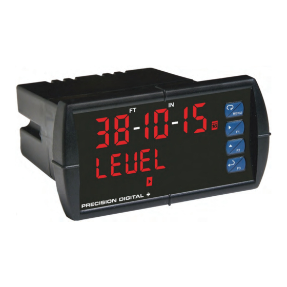
PD6001 Analog Input Feet & Inches Meter
RO
U
" & 0.46"
GlobalTestSupply
www.
Digits
P
R
S
USB Install
Process
.com
sales@GlobalTestSupply.com
V
U
®
ERIES
Advertisement
Table of Contents
Troubleshooting

Related Manuals for PRECISION DIGITAL PROVU PD6001


Summary of Contents for PRECISION DIGITAL PROVU PD6001
- Page 1 2 or 4 Relays + Isolated 4-20 mA Output Options USB, RS-232, & RS-485 Serial Communication Options External 4-Relay & Digital I/O Expansion Modules Input Power Options Include 85-265 VAC or 12-24 VDC PRECISION DIGITAL CORPORATION GlobalTestSupply www. .com Find Quality Products Online at: sales@GlobalTestSupply.com...
-
Page 2: Limited Warranty
Disclaimer The information contained in this document is subject to change without notice. Precision Digital makes no representations or warranties with respect to the contents hereof and specifically disclaims any implied warranties of merchantability or fitness for a particular purpose. -
Page 3: Table Of Contents
PD6001 Analog Input Feet & Inches Meter Instruction Manual Table of Contents Table of Contents -------------------------------------------3 Relay and Alarm Operation Diagrams ----------------- 28 Table of Figures ---------------------------------------------4 High Alarm Operation (Set > Reset) ------------------- 29 Low Alarm Operation (Set < Reset) -------------------- 29 ... -
Page 4: Table Of Figures
PD6001 Analog Input Feet & Inches Meter Instruction Manual Table of Figures Figure 1. 1/8 DIN Panel Cutout Dimensions ....9 Figure 11. Relay Connections ........13 Figure 2. Panel Mounting Details ........9 Figure 12. AC and DC Loads Protection ...... 13 ... -
Page 5: Ordering Information
PD6001 Analog Input Feet & Inches Meter Instruction Manual Ordering Information Standard Models 85-265 VAC Model 12-24 VDC Model Options Installed PD6001-6R0 PD6001-7R0 No options PD6001-6R2 PD6001-7R2 2 relays (PD1102*) PD6001-6R3 PD6001-7R3 4-20 mA output (PD1103*) PD6001-6R4 PD6001-7R4 4 relays (PD1104*) PD6001-6R5 PD6001-7R5 2 relays &... -
Page 6: Specifications
PD6001 Analog Input Feet & Inches Meter Instruction Manual Specifications Except where noted all specifications apply to operation at +25°C. General Fuse Required external fuse: UL Recognized, 5 A max, slow blow; up to 6 meters may Display Line 1: 0.60" (15 mm) high, red LEDs share one 5 A fuse separated by feet and inches Normal Mode... -
Page 7: Relays
PD6001 Analog Input Feet & Inches Meter Instruction Manual Decimal Point Up to five decimal places or none (PV2 Fail-Safe Programmable and independent for only): Operation each relay. d. d dddd, d. d ddd, d. d dd, d. d d, d. d , Note: Relay coil is energized in non- dddddd alarm condition. -
Page 8: Compliance Information
PD6001 Analog Input Feet & Inches Meter Instruction Manual Compliance Information Safety UL & c-UL Listed USA & Canada UL 508 Industrial Control Equipment UL File Number E160849 Front Panel UL Type 4X, NEMA 4X, IP65; panel gasket provided Low Voltage EN 61010-1:2010 Directive Safety requirements for measurement, control, and laboratory use... -
Page 9: Safety Information
PD6001 Analog Input Feet & Inches Meter Instruction Manual Safety Information CAUTION: Read complete WARNING: Risk of electric shock or instructions prior to installation and personal injury. operation of the meter. Hazardous voltages exist within enclosure. Installation and service should be performed Warning! only by trained service personnel. -
Page 10: Mounting Dimensions
PD6001 Analog Input Feet & Inches Meter Instruction Manual Mounting Dimensions Figure 3. Meter Dimensions - Side View Figure 4. Meter Dimensions - Top View Transmitter Supply Voltage Selection (P+, P-) All meters, including models equipped with the 12-24 VDC power option, are shipped from the factory configured to provide 24 VDC power for the transmitter or sensor. -
Page 11: Connections
The connectors’ label, affixed to the meter, shows the location of all connectors available with requested configuration. Do not connect any equipment other than Precision Digital’s expansion modules, cables, or meters to the RJ45 M-LINK connector. Warning! Otherwise damage will occur to the equipment and the meter. -
Page 12: Signal Connections
PD6001 Analog Input Feet & Inches Meter Instruction Manual Signal Connections Signal connections are made to a six-terminal connector labeled SIGNAL on Figure 6. The COM (common) terminal is the return for the 4-20 mA and the 10 V input signals. Current and Voltage Connections The following figures show examples of current and voltage connections. -
Page 13: Modbus Rtu Serial Communications
Figure 13. Low Voltage DC Loads Protection RC Networks Available from Precision Digital RC networks are available from Precision Digital and should be applied to each relay contact switching an inductive load. Part number: PDX6901. Note: Relays are de-rated to 1/14th HP (50 watts) with an inductive load. -
Page 14: F4 Digital Input Connections
PD6001 Analog Input Feet & Inches Meter Instruction Manual F4 Digital Input Connections A digital input, F4, is standard on the meter. This digital input is connected with a normally open contact across F4 and COM, or with an active low signal applied to F4. Figure 14. -
Page 15: External Relays & Digital I/O Connections
PD6001 Analog Input Feet & Inches Meter Instruction Manual External Relays & Digital I/O Connections The relay and the digital I/O expansion modules PDA1004 & PDA1044 are connected to the meter using a CAT5 cable provided with each module. The two RJ45 connectors on the expansion modules are identical and interchangeable;... -
Page 16: Setup And Programming
PD6001 Analog Input Feet & Inches Meter Instruction Manual Setup and Programming The meter is factory calibrated prior to shipment to read in milliamps and volts depending on the input selection. The calibration equipment is certified to NIST standards. Overview There are no jumpers to set for the meter input selection. -
Page 17: Meterview ® Pro Software
PD6001 Analog Input Feet & Inches Meter Instruction Manual ® MeterView Pro Software The meter can also be programmed using the PC-based MeterView Pro software included with the meter. This software can be installed on any Microsoft® Windows® (XP/Vista/7/8/10) computer by connecting the meter’s onboard USB. -
Page 18: Display Functions & Messages
PD6001 Analog Input Feet & Inches Meter Instruction Manual Display Functions & Messages The meter displays various functions and messages during setup, programming, and operation. The following table shows the main menu functions and messages in the order they appear in the menu. Display Parameter Action/Setting... - Page 19 PD6001 Analog Input Feet & Inches Meter Instruction Manual Display Parameter Action/Setting Display Parameter Action/Setting Description Description FLS 1 Set relay 1 fail-safe Aout Enter the Analog output Fail-safe 1 Analog operation scaling menu output Enable fail-safe operation Dis 1 Program display 1 value Display 1 Disable fail-safe operation...
-
Page 20: Main Menu
PD6001 Analog Input Feet & Inches Meter Instruction Manual Main Menu The main menu consists of the most level commonly used functions: Setup, Reset, Control, and Password. Press Menu button to enter Programming Mode then press the Up arrow button to scroll main menu. ... -
Page 21: Setting Up The Meter (Setup)
PD6001 Analog Input Feet & Inches Meter Instruction Manual Setting Up the Meter (setup) The Setup menu is used to select: 1. Input signal the meter will accept 2. Dual-scale feature for some level applications 3. Select the display units/tags Note: Use the d-SCAL selection 4. -
Page 22: Setting The Input Units Or Custom Tags (Units)
PD6001 Analog Input Feet & Inches Meter Instruction Manual Setting the Input Units or Custom Tags (units) Enter the input unit or custom tag that will be displayed if d unit is selected as the display line 2 parameter. See the flow chart on page 26 to access the display menu to show the unit or tag on line 2. The engineering units or custom legends can be set using the following 7-segment character set: Display Character... -
Page 23: Programming The Meter (Prog)
PD6001 Analog Input Feet & Inches Meter Instruction Manual Programming the Meter (prog) It is very important to read the following information, before proceeding to program the meter: The meter is factory calibrated prior to shipment to read in milliamps and volts depending on the input selection. - Page 24 PD6001 Analog Input Feet & Inches Meter Instruction Manual Scaling the Meter (SCALE) The process input (4-20 mA, 10 VDC) can be scaled to display the process variable in engineering units. A signal source is not needed to scale the meter; simply program the inputs and corresponding display values.
- Page 25 PD6001 Analog Input Feet & Inches Meter Instruction Manual Calibrating the Meter with External Source (Cal) Note: To scale the meter without a signal source refer to Scaling the Meter (SCALE), page 24. The meter can be calibrated to display the process variable in engineering units by applying the appropriate input signal and following the calibration procedure.
-
Page 26: Setting The Display Parameter & Intensity (Dsplay)
PD6001 Analog Input Feet & Inches Meter Instruction Manual Setting the Display Parameter & Intensity (dsplay) Display line 1 can be programmed to display: 1. Process value 2. Relay set points 3. Max & min values 4. Modbus input Display line 2 can be programmed to display: 1. -
Page 27: Setting The Relay Operation (Relay)
PD6001 Analog Input Feet & Inches Meter Instruction Manual Setting the Relay Operation (relay) This menu is used to set up the operation of the relays. During setup, the relays do not follow the input and they will remain in the state found prior to entering the Relay menu. Caution! 1. -
Page 28: Setting The Relay Action
PD6001 Analog Input Feet & Inches Meter Instruction Manual Setting the Relay Action Operation of the relays is programmed in the Action menu. The relays may be set up for any of the following modes of operation: 1. Automatic reset (non-latching) 2. -
Page 29: High Alarm Operation (Set > Reset)
PD6001 Analog Input Feet & Inches Meter Instruction Manual High Alarm Operation (Set > Reset) Low Alarm Operation (Set < Reset) For Manual reset mode, ACK can be pressed anytime For Manual reset mode, ACK can be pressed anytime to turn "off" relay. To detect a new alarm condition, the to turn "off"... -
Page 30: High Alarm With Fail-Safe Operation (Set > Reset)
PD6001 Analog Input Feet & Inches Meter Instruction Manual High Alarm with Fail-Safe Low Alarm with Fail-Safe Operation Operation (Set > Reset) (Set < Reset) Note: Relay coil is energized in non-alarm Note: Relay coil is energized in non-alarm condition. In case of power failure, relay will condition. -
Page 31: Pump Alternation Control Operation
PD6001 Analog Input Feet & Inches Meter Instruction Manual Pump Alternation Control Operation Relay Sampling Operation Input Reset Sample Sample Sample Time Time Time Relay When the signal crosses the set point, the relay trips and the sample time starts. After the sample time has elapsed, the relay resets. -
Page 32: Signal Loss Or Loop Break Relay Operation
PD6001 Analog Input Feet & Inches Meter Instruction Manual Signal Loss or Loop Break Relay Operation The following graph shows the loop break relay operation for a high alarm relay. Input Reset de-energized energized Relay Loop Break = Ignore Relay Loop Break = Off Relay Loop Break = On... -
Page 33: Relay Operation Details
PD6001 Analog Input Feet & Inches Meter Instruction Manual Relay Operation Details Overview The relay capabilities of the meter expand its usefulness beyond simple indication to provide users with alarm and control functions. These capabilities include front panel alarm status LEDs as well as either 2 or 4 optional internal relays and/or 4 external relays expansion module. -
Page 34: Latching And Non-Latching Relay Operation
PD6001 Analog Input Feet & Inches Meter Instruction Manual Latching and Non-Latching Relay Operation The relays can be set up for latching (manual reset) or Relay terminology for following tables non-latching (automatic reset) operation. Terminology Relay Condition The On and Off terminology does not refer to the status of Alarm (Tripped) the relay’s coil, which depends on the fail-safe mode Normal (Reset) -
Page 35: Acknowledging Relays
PD6001 Analog Input Feet & Inches Meter Instruction Manual Acknowledging Relays There are two ways to acknowledge relays programmed for manual reset: 1. Via the programmable front panel function keys F1-F3 (Default: F3 assigned to ACK). 2. Remotely via a normally open pushbutton wired across one of the digital inputs and the +5 V terminals on the digital I/O modules, or using the F4 digital input, which is triggered with a contact closure to COM, or with an active low signal (see page 14). - Page 36 PD6001 Analog Input Feet & Inches Meter Instruction Manual Application #2: Pump Alternation Using Relays 3 & 4 1. Relays 1 and 2 are set up for low and high alarm indication. 2. Relays 3 and 4 are set up for pump alternation. Set and Reset Point Programming Relay Set Point...
-
Page 37: Setting Up The Interlock Relay (Force On) Feature
PD6001 Analog Input Feet & Inches Meter Instruction Manual Setting Up the Interlock Relay (Force On) Feature Relays 1-4 can be set up as interlock relays. To set up the relays for the interlock feature: 1. Access the Setup – Relay – Action menu and set the action to off. 2. -
Page 38: Reset Menu (Reset)
PD6001 Analog Input Feet & Inches Meter Instruction Manual Reset Menu (reset) The Reset menu is used to reset the maximum or minimum reading (peak or valley) reached by the process; both may be reset at the same time by selecting “reset high & low” (rst HL). Control Menu (Contrl) The Control menu is used to control the 4-20 mA analog output and the relays manually, ignoring the input. -
Page 39: Making Changes To A Password Protected Meter
PD6001 Analog Input Feet & Inches Meter Instruction Manual Making Changes to a Password Protected Meter If the meter is password protected, the meter will display the message Locd (Locked) when the Menu button is pressed. Press the Enter button while the message is being displayed and enter the correct password to gain access to the menu. -
Page 40: Advanced Features Menu
PD6001 Analog Input Feet & Inches Meter Instruction Manual Advanced Features Menu To simplify the setup process, functions not needed for most applications are located in the Advanced Features menu. Press and hold the Menu button for three seconds to access the advanced features of the meter. Advanced Features Menu &... - Page 41 PD6001 Analog Input Feet & Inches Meter Instruction Manual Display Parameter Action/Setting Display Parameter Action/Setting Calibrate 4-20 mA output Min on line 2 Calib Ln2 lo Calibrate Line 2 Low (internal reference source Max/min line 2 Ln2 Hl Line 2 used for scaling the output) High/Low 4 mA...
-
Page 42: Noise Filter (Filter)
PD6001 Analog Input Feet & Inches Meter Instruction Manual Noise Filter (filter) The noise filter is available for unusually noisy signals that cause an unstable process variable display. The noise filter averages the input signal over a certain period. The filter level determines the length of time over which the signal is averaged. -
Page 43: Modbus Rtu Serial Communications (Serial)
PD6001 Analog Input Feet & Inches Meter Instruction Manual Modbus RTU Serial Communications (serial) The meter is equipped with serial communications capability as a standard feature using Modbus RTU Serial Communication Protocol. The meter may be connected to a PC for initial configuration via the onboard micro USB connection. For ongoing digital communications with a computer or other data terminal equipment, an RS-232, or RS-485 Do not connect any equipment other than Precision Digital’s expansion modules, cables, or meters to the RJ45 M-LINK connector. -
Page 44: Signal Input Conditioning (Functn)
PD6001 Analog Input Feet & Inches Meter Instruction Manual Signal Input Conditioning (Functn) The Function menu is used to select the signal input conditioner applied to the input: linear or round horizontal tank volume calculation. Multi-point linearization is part of the linear function selection. -
Page 45: Low-Flow Cutoff (Cutoff)
PD6001 Analog Input Feet & Inches Meter Instruction Manual Low-Flow Cutoff (CutofF) The low-flow cutoff feature allows the meter to be programmed so that the often-unsteady outputs from level transmitters, or levels that read close to zero but do not reach zero due to setup constraints, may display zero on the meter. -
Page 46: Programmable Function Keys User Menu (User)
PD6001 Analog Input Feet & Inches Meter Instruction Manual Programmable Function Keys User Menu (user) The User menu allows the user to assign the front panel function keys F1, F2, and F3, the digital input F4 (a digital input located on the signal input connector), and up to eight additional digital inputs to access most of the menus or to activate certain functions immediately (e.g. -
Page 47: Internal Source Calibration (Ical)
PD6001 Analog Input Feet & Inches Meter Instruction Manual Internal Source Calibration (ICAL) The meter is factory calibrated prior to shipment to read in milliamps and volts depending on the input selection. The calibration equipment is certified to NIST standards. The use of calibrated signal sources is necessary to calibrate the internal source of the meter. -
Page 48: Meter Operation
PD6001 Analog Input Feet & Inches Meter Instruction Manual Meter Operation The meter is capable of accepting current (0-20 mA, 4-20 mA) and voltage signals (0-5 V, 1-5 V, 0-10 V, 10 V) and displaying these signals in engineering units from -9 ) - 99 ) on display line 1 and units from -99999 to 999999 on display line 2 (e.g. -
Page 49: Maximum/Minimum Readings
PD6001 Analog Input Feet & Inches Meter Instruction Manual Maximum/Minimum Readings The max & min readings (peak & valley) reached by the process can be displayed either continuously or momentary: 1. Display briefly by assigning to the F1-F3 function keys or to the digital inputs in the User menu. 2. -
Page 50: Troubleshooting
PD6001 Analog Input Feet & Inches Meter Instruction Manual Troubleshooting Due to the many features and functions of the meter, it’s possible that the setup of the meter does not agree with what an operator expects to see. If the meter is not working as expected, refer to the Diagnostics menu and consult the recommendations described below. -
Page 51: Factory Defaults & User Settings
PD6001 Analog Input Feet & Inches Meter Instruction Manual Factory Defaults & User Settings The following table shows the factory setting for most of the programmable parameters on the meter. Parameter Display Default Setting Parameter Display Default Setting Off delay relay 3 0.0 sec Input type Input... -
Page 52: Troubleshooting Tips
PD6001 Analog Input Feet & Inches Meter Instruction Manual Troubleshooting Tips Symptom Check/Action No display at all Check power at power connector Not able to change setup or programming, Meter is password-protected, enter correct six-digit Locd is displayed password to unlock Check: Meter displays error message during 1. -
Page 53: Eu Declaration Of Conformity
EN 55022:2010, EN 61000-6-2:2005, EN 61010-1:2010, and EN 61326:2013 and there were no major technical changes affecting the latest technical knowledge for the products listed above. Product Markings: Signed for and on behalf of Precision Digital Corporation: Name: Jeffrey Peters Company:... - Page 54 PD6001 Analog Input Feet & Inches Meter Instruction Manual PRECISION DIGITAL CORPORATION LIM6001_E SFT109 Ver 4.000 & up 03/17 GlobalTestSupply www. .com Find Quality Products Online at: sales@GlobalTestSupply.com...
Need help?
Do you have a question about the PROVU PD6001 and is the answer not in the manual?
Questions and answers