Table of Contents
Advertisement
Quick Links
Advertisement
Chapters
Table of Contents

Related Manuals for Anderson RB 580


Summary of Contents for Anderson RB 580
- Page 1 #404611-10 Round Bale Wrapper RB 580 Operator’s Manual 2021-23...
- Page 3 In case of sale or transfer, give this manual to the new owner. The illustrations in this manual are presented for your reference according to the latest information available at the moment of printing. ANDERSON EQUIPMENT reserves the right to modify its machines without advance notice.
-
Page 4: Table Of Contents
Table of Contents 1 Anderson limited warranty ....................4 2 Safety ..........................7 Safe Operators ......................7 Danger Zone ......................7 Secure Attachment to the Tractor ................7 Dangerous Situations ....................7 Prevention ......................... 7 Safe Maintenance and Repair ..................7 Fuel ........................... - Page 5 - Product model and serial number; - Purchase date and invoice number; - Dealer name, address, and telephone number and salesperson name; - Precise and detailed description of your problem. ANDERSON EQUIPMENT Address: 5125 de la Plaisance Chesterville (Québec) CANADA G0P 1J0 Email Service: support@grpanderson.com...
-
Page 6: Anderson Limited Warranty
In no event will Anderson be liable for any incidental or consequential damages or injuries, including but not limited to loss of profits, rental of substitute equipment, or other commercial or personal loss or damages arising as a result of a fundamental breach or breach of a fundamental term. - Page 7 The fundamental responsibility of warranty is to correct defects in material and workmanship of the products sold by Group Anderson Inc. (hereafter called ‘’Anderson’’). This outline is intended to assist you in awareness of Anderson’s Warranty Policies and to assure that you obtain the best service possible for your Anderson machine. ...
- Page 8 Anderson’s Responsibilities: In the event that parts must be shipped from Anderson, freight will be paid by Anderson and will be shipped by the most economical means to arrive in the shortest possible time. Air, Next Day Air, Priority and other special shipment methods requested by the Dealer will be at the Customer’s expense.
-
Page 9: Safety
2 Safety Your ANDERSON bale wrapper was designed to reduce to a minimum the risks to the operator. However, it must be used only for the work it was designed for. Additionally, since it includes a powerful hydraulic system, moving metal parts, and a gasoline engine (optional) and all these elements can cause serious injury to humans or animals, it is strongly recommended to read and to closely adhere to the following guidelines. -
Page 10: Fuel
Fuel Gasoline is a very flammable substance which must be handled with care in an approved container when you fill the engine tank of your hydraulic unit. Put back in place and firmly tighten the tank cap and wipe away any spilled fuel. Never add gasoline when the engine is hot or operating. -
Page 11: General Characteristics And Specifications
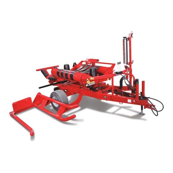
3 General Characteristics and Specifications Congratulations! You are now the owner of an ANDERSON bale wrapper, a high-quality machine designed for the separate storage of round bales of up to 5 feet (1.5m) in diameter. This agricultural machine is carefully manufactured by our company to give you many years of reliable performance. -
Page 12: General Specifications
General Specifications Figure 3.2 Exterior dimensions Dimensions and Weight for base model Length (A) 187 po (4,77m) Width (B) 101 po (2,56m) Height (C) 116 po (2,98m) Total weight* 3703 lbs (1680 kg) 4 Adjustment Procedures Verifications Before Each Use If necessary, lubricate the machine well after each day of use. - Page 13 Figure 4.1 Installing the film roll Follow the diagram (Figure 4.2) to unroll the start of the film between the rubber roller and an aluminium roller, then around the other aluminium roller. The edge of the plastic must be attached onto the ties or the net of the first bale. Figure 4.2 Direction of film unwinding Avoid leaving the plastic film rolls in the sun for a long period of time before using them.
-
Page 14: Testing The Plastic Film Stretcher
Testing the Plastic Film Stretcher To check the effectiveness of your system, draw a 10-inch (25 cm) horizontal line on your plastic film roll with a felt-tip pen. Turn the table about one revolution and stop. Once the line has passed the aluminum rollers, measure it on the bale. If it has stretched up to a length of approximately 16.5 inches (41 cm), this means that your film stretcher is working properly. -
Page 15: Operating Procedures
The module consists of a 2-line screen with 4 buttons beneath it. Start up the counter by touching the ON/OFF button on the left. This opens the first Anderson window. Five seconds later, the screen will look as follows: - In the upper left corner of this window, rev: 00 will count each wrapping as you operate the bale wrapper. -
Page 16: Advanced Menu Of The Ig-C3 Bale Counter
Operation Menu of the IG-C3 Bale Counter - If you press the ER. COUNT. DAY. button, the screen will ask you to confirm NO or YES + whether you really want to erase the daily counter. - Similarly, the .ER. COUNT. REV. button allows you to reset the revolution counter to zero during a test or during a missed cycle. -
Page 17: Levers
Levers FONCTION Wrapping lever Tilt the table Figure 5.2 580 Levers First Bale Take a round bale with the loading arm and place it in the center of the feed rollers. The bale will turn counterclockwise. Attach the edge of the plastic film to the ties or net of the bale. Pull the wrapping lever (1). -
Page 18: Bale Wrapping: Adjusting The Sensors
5.4 Bale Wrapping: Adjusting the Sensors Adjusting the Rotation Counter Sensor Place the 2 parts of the sensor at position 1 so that they face each other, turning the table by pulling the control valve lever, and adjust the distance between them to 1/8 inch (2.5 mm)(Figure 5.3) Figure 5.3 Rotation counter sensor 5.5 Adjusting the Mechanical Plastic Film Cutter... - Page 19 Figure 5.5 Stopper spring and adjustment bolt Figure 5.6 Adjusting the plastic film cutter blade (at rest)
-
Page 20: Maintenance Procedures
Warning ! Grease Gun Lubrication Your ANDERSON bale wrapper must be lubricated with a grease gun in the places indicated by the sticker (Figure 6.1). Figure 6.1 Grease gun lubrication Note: The use of synthetic grease is highly recommended... - Page 21 Central axle of turntable (1 on the top) Pivots of tilting table (2) Axles of the tilting cylinder...
- Page 22 Axles of the unloading platform cylinder Pivot of the unloading arm Axles of the unloading arm cylinder (2)
- Page 23 Pivot of the unloading platform (4) Bearings of the two feed rollers of the belts (1 on each end, total of 4)
-
Page 24: Other Lubrication Points
Other Lubrication Points The power transmission chains and other moving parts of the machine must be oiled or greased regularly or every 50 hours. This also applies to the 2 toothed wheels of the plastic film stretcher. Figure 6.2 Lubricating the plastic film stretcher Figure 6.3 Lubricating the chain (through the hole in the guard) The film cutter must be lubricated daily (approximately 100 balls) where indicated in the following figures:... -
Page 25: Cleaning And Other Maintenance
Figure 6.4 Lubricating the plastic film cutter 1 Figure 6.5 Lubricating the plastic film cutter 2 Cleaning and Other Maintenance Pay particular attention to the cleanliness of the plastic film cutter system. An accumulation of debris (hay, dust, string, etc.) can reduce its functionality. Regularly check the cutting condition of the blade. -
Page 26: Storage
Storage To unhitch the machine, follow these steps: During unhitching operations, the operator is the only person authorized to be near the machine. Before lowering the tractor to remove the hydraulic connections, and the electric cables, the operator must ensure that the machine is fully Warning ! on the ground and stable. -
Page 27: Troubleshooting: Problems And Solutions
7 Troubleshooting: Problems and Solutions Before calling a technician, examine your machine and consult the table below to find a solution. If you are still not able to solve the problem yourself, ask for help from the customer service department of your agricultural dealer. Troubleshooting Table Problems Possible Causes... -
Page 28: Feature And Optional Equipment
Bale Loading Arm and Plastic Film Roll Support As an option, a loading arm can be installed on the bale wrapper only at Anderson manufacture. This arm makes it possible to load bales directly onto the bale wrapper without using a frontal loader. -
Page 29: Unloading Platform (D3)
Unloading Platform (D3) Figure 8.2 Bale unloading platform D3 This optional equipment makes it possible to bring the bales to a vertical position and set them down on the flat side. Additionally, this unloading platform makes it possible to turn bales on one side or the other according to the preference of the user. - Page 30 Installation of the three position unloading platform (D3) Here are the steps to install the unloading platform D3 from the unloading platform D : Installation of the foot Sand the shaft. Slide the foot on the shaft and lock in place with the linchpin. (1).
- Page 31 Place the support on the dumping unit and bolt into place. Holes on the dumper are predrilled from the factory. Installation of the retaining arm Insert the fixed part of the arm into the support. You can now attach the ‘’L’’ shaped bar to the straight bar.
- Page 32 Installation of the cone shaped roller Remove the deflector at the end of the dumper to reveal the placement holes for the cone shaped roller. Place the cone shaped roller on the same side as the foot as you will be bumping the bale to the opposite side.
-
Page 33: Double Roll Plastic Unit
Remove the handle (1). Turn the lock washer (2) that its lock the handle. 10. Replace the handle (1). Figure 8.3 Accumulator of the unloading arm If using a tractor for this procedure we recommend that you put a relief valve between the wrapper and the tractor. -
Page 34: Start-Up Procedures
9 Start-Up Procedures When you receive your new ANDERSON equipment: Remove the table barrier on the bale wrapper (Figure 2.1). Install a plastic film roll (Figure 4.1). Enable the tractor hydraulic system. Place a bale on the table with the loading arm. - Page 35 Parts manual ROUND BALE WRAPPER RB580 ALWAYS KEEP THIS MANUAL WITH THE WRAPPER...
- Page 37 17 - Electric diagram For any parts order, please use the parts manual to find the item(s) you need and contact your dealer to order it or contact us directly at : ANDERSON GROUP 5125 de la Plaisance Chesterville (Québec)
-
Page 38: Main Frame
1 - MAIN FRAME Anderson Group, 5125 de la Plaisance Chesterville (Québec) G0P 1J0 Email : service@grpanderson.com... - Page 39 FLAT WASHER 7/16 Z 451261 6 M.JIC - 8 M.ORB 500017 HEX BOLT GR5 1/4-20 X 2 1/2 502002 FLAT WASHER 1/4 Z 501057 HEX HALF NUT GR5 1-8 Z Anderson Group, 5125 de la Plaisance Chesterville (Québec) G0P 1J0 Email : service@grpanderson.com...
- Page 40 DETAIL A PARTS LIST ITEM PART DESCRIPTION NOTE 222002 TONGUE 501032 HEX NYLON LOCKNUT GR5 3/8-16 Z 322450 JACK 500445 CARRIAGE BOLT GR5 3/8-16 X 1 3/4 Z Anderson Group, 5125 de la Plaisance Chesterville (Québec) G0P 1J0 Email : service@grpanderson.com...
- Page 41 JOINT RADIAL 2500-2 1-2 X 1 3-4 -A 481000 BOUCHON ANTI-POUSSIÈRE 507010 BOULON DE ROUE 1/2-20 X 1 1/2 481100 ESSIEU 320020 GOUPILLE 501100 DEMI ÉCROU CHÂTEAU HEX GR5 1-12 303038 RONDELLE POUR ESSIEUX Anderson Group, 5125 de la Plaisance Chesterville (Québec) G0P 1J0 Email : service@grpanderson.com...
-
Page 42: Stretcher Support Arm
CARRIAGE BOLT GR5 3/8-16 X 1 Z 501032 HEX NYLON LOCKNUT GR5 3/8-16 Z 501024 HEX FLANGE NUT GR2 1/2-13 Z 224262 DUMPING TABLE SAFTY PLATE 320023 LOCK PIN 5/16 X 2 1/2 Anderson Group, 5125 de la Plaisance Chesterville (Québec) G0P 1J0 Email : service@grpanderson.com... -
Page 44: Stretcher Support
5 - STRETCHER SUPPORT Anderson Group, 5125 de la Plaisance Chesterville (Québec) G0P 1J0 Email : service@grpanderson.com... - Page 45 RETAINNING RING EXT. 3/4 B 325181 CABLE 304007 SPRING 224079 PIN FOR RUBBER ROLL 224077-1 PIN FOR ROLL HOLDER 500084 HEX BOLT GR5 3/8-16 X 1 502014 FLAT WASHER 5/16 Z Anderson Group, 5125 de la Plaisance Chesterville (Québec) G0P 1J0 Email : service@grpanderson.com...
-
Page 46: Stretcher
6- STRETCHER Anderson Group, 5125 de la Plaisance Chesterville (Québec) G0P 1J0 Email : service@grpanderson.com... - Page 47 507003 HEX SOCKET SET SCREW CUP 1/4-20 X 1/2 500042 HEX BOLT GR5 5/16-18 X 3/4 501021 HEX FLANGE NUT GR2 5/16-18 Z 279103 GEAR 279104 GEAR Anderson Group, 5125 de la Plaisance Chesterville (Québec) G0P 1J0 Email : service@grpanderson.com...
- Page 48 7- DUMPING TABLE 1.11 1.10 1.20 1.12 1.18 1.19 1.13 1.14 1.16 1.21 1.17.1 1.15 1.17.1 1.17.2 Anderson Group, 5125 de la Plaisance Chesterville (Québec) G0P 1J0 Email : service@grpanderson.com...
-
Page 49: Dumping Table
NOTE 467029 DOMP. TABLE CYLINDER 322295 GREASE FITTING 450543 HYDRAULIC FITTING 465878 CHECK VALVE 451261 6 M.JIC - 8 M.ORB 450165 8 M.ORB - 8 M.NPT 90° Anderson Group, 5125 de la Plaisance Chesterville (Québec) G0P 1J0 Email : service@grpanderson.com... - Page 50 7 - DUMPING TABLE Anderson Group, 5125 de la Plaisance Chesterville (Québec) G0P 1J0 Email : service@grpanderson.com...
- Page 51 HEX WHEEL NUT 5/8-18 221004 ENGRENAGE PRINCIPAL 320002 COTTER PIN 3/16 X 2 Z 501100 HEX HALF CASTLE NUT 1-12 325141-1 KEY 1/4 X 1/4 X 1 1/2 Anderson Group, 5125 de la Plaisance Chesterville (Québec) G0P 1J0 Email : service@grpanderson.com...
-
Page 52: Shield
CARRIAGE BOLT GR5 3/8-16 X 1 Z 501022 HEX FLANGE NUT GR2 3/8-16 Z 502045 LOCK WASHER 3/8 465918 HYDRAULIC VALVE 507041-2 SQUARE DRIVES SELF-THREADING SCREW 10-24 X 3/4 Z Anderson Group, 5125 de la Plaisance Chesterville (Québec) G0P 1J0 Email : service@grpanderson.com... - Page 54 9 - ROTARY TABLE Anderson Group, 5125 de la Plaisance Chesterville (Québec) G0P 1J0 Email : service@grpanderson.com...
- Page 55 500401 CARRIAGE BOLT 320023 LOCK PIN 2 1/2 502008 FLAT WASHER 5/8 Z 500104 HEX BOLT GR5 3/8-16 X 4 501032 HEX NYLON LOCKNUT GR5 3/8-16 Z Anderson Group, 5125 de la Plaisance Chesterville (Québec) G0P 1J0 Email : service@grpanderson.com...
-
Page 56: Rotary Table And Cut And Hold
9 - ROTARY TABLE AND CUT AND HOLD PARTS LIST ITEM PART DESCRIPTION NOTE 22287 CUT AND HOLD BOTTOM SECTION 222087 CUT AND HOLD BOTTOM SECTION 223049 HOLDING ROLLER 222008 ROTARY TABLE Anderson Group, 5125 de la Plaisance Chesterville (Québec) G0P 1J0 Email : service@grpanderson.com... - Page 58 9 - CUT AND HOLD 15.1 15.2 15.3 15.2 Anderson Group, 5125 de la Plaisance Chesterville (Québec) G0P 1J0 Email : service@grpanderson.com...
- Page 59 HEX NYLON LOCKNUT GR5 3/8-24 Z 222062 COVER 222057 RICHARD BLADE U-1-B-B 222061 COVER SUPPORT 500052 HEX BOLT GR5 5/16-18 X 2 304071 SPRING 501031 HEX NYLON LOCKNUT GR5 5/16-18 Z Anderson Group, 5125 de la Plaisance Chesterville (Québec) G0P 1J0 Email : service@grpanderson.com...
- Page 60 9 - CUT AND HOLD Anderson Group, 5125 de la Plaisance Chesterville (Québec) G0P 1J0 Email : service@grpanderson.com...
- Page 61 HEX BOLT GR5 3/8-16 X 1 1/2 222082 MOUNTING PLATE BEARING 303021-1 BEARING 6203-5-8-RS 320055 RETAINING RING 304026 SPRING 500082 HEX BOLT GR5 3/8-16 X 3/4 222081 TRANSFER PLATE Anderson Group, 5125 de la Plaisance Chesterville (Québec) G0P 1J0 Email : service@grpanderson.com...
-
Page 62: Loading Arm
223087-1 223055 LOCK 223056 BALE STOPPER 500501 CARRIAGE BOLT GR5 1/2-13 X 1 1/4 501024 HEX FLANGE NUT GR2 1/2-13 Z 223057-1 LOADING ARM FRAME 303052 BUSHING Anderson Group, 5125 de la Plaisance Chesterville (Québec) G0P 1J0 Email : service@grpanderson.com... - Page 63 HEX FLANGE NUT GR2 1/2-13 Z 500501 CARRIAGE BOLT GR5 1/2-13 X 1 1/4 500173 HEX BOLT GR5 1/2-13 X 1 502048 LOCK WASHER 1/2 223083 COUNTERWEIGHT 223082 SUPPORT Anderson Group, 5125 de la Plaisance Chesterville (Québec) G0P 1J0 Email : service@grpanderson.com...
- Page 64 HEX FLANGE NUT GR2 1/2-13 Z 500096 HEX BOLT GR5 3/8-16 X 2 1/2 501032 HEX NYLON LOCKNUT GR5 3/8-16 Z 500088 HEX BOLT GR5 3/8-16 X 1 1/2 Anderson Group, 5125 de la Plaisance Chesterville (Québec) G0P 1J0 Email : service@grpanderson.com...
- Page 65 465489 CABLE 3.5 M 451229 8 M.JIC - 8 M.ORB 45° 451227 6 M.JIC - 8 M.ORB 45° 451356 PLUG ORB 10 451355 PLUG 8 M. ORB Anderson Group, 5125 de la Plaisance Chesterville (Québec) G0P 1J0 Email : service@grpanderson.com...
- Page 66 SCREW 10/24 X 2 1/2 Z 501049 HEX NYLON LOCKNUT GR5 #10-24 501077-1 BOLT 500044 HEX BOLT GR5 5/16-18 X 1 502014 FLAT WASHER 5/16 Z 222051 COMPLET CONTROL KIT Anderson Group, 5125 de la Plaisance Chesterville (Québec) G0P 1J0 Email : service@grpanderson.com...
- Page 67 223225 580-680 LEFT LIGHT PROTECTOR 500180 HEX BOLT GR5 1/2-13 X 2 900562 CONTOUR LIGHT 900563 REFLECTOR 234223-1 580-680 STANDARD LIGHT KIT 315111 580-680 TRAILER PLUG Anderson Group, 5125 de la Plaisance Chesterville (Qu bec) G0P 1J0 Email : service@grpanderson.com...
-
Page 68: Drop Off (Option)
13 - DROP OFF 23 39 40 Groupe Anderson, 5125 de la Plaisance Chesterville (Québec) G0P 1J0 GRPANDERSON.COM... - Page 69 502014 FLAT WASHER 5/16 Z 501022 HEX FLANGE NUT GR2 3/8-16 Z 223188 ROLLER SUPPORT 325107 325112 PLASTIC CONE 303045 BEARING 1654-Z 320006 RETAINING RING 320039 HITCH PIN 3/16 Groupe Anderson, 5125 de la Plaisance Chesterville (Québec) G0P 1J0 GRPANDERSON.COM...
- Page 70 HEX FLANGE NUT GR2 1/2-13 Z 501024 HEX FLANGE NUT GR2 1/2-13 Z 500501 CARRIAGE BOLT GR5 1/2-13 X 1 1/4 Z 223183 LOWER FIXED PART 223184 UNSEATABLE PART OF THE ARM Groupe Anderson, 5125 de la Plaisance Chesterville (Québec) G0P 1J0 Email : service@grpanderson.com...
- Page 71 2X 5315-6-8 5315-6-8 5315-6-8 LIMITEUR DE PRESSION MOTEUR DE TABLE PIVOTANTE VALVE DÉVIA. TABLE BASCULENTE RELIEF VALVE ROTARY TABLE MOTOR DIVERTER VALVE TILTING TABLE Groupe Anderson / Anderson Group, 5125 de la Plaisance Chesterville (Québec) G0P 1J0 Email : service@anderson-equipment.com...
- Page 72 09-08 223108-1 09-09 223109-1 09-28 223128-1 09-29 223129-1 09-32 223132 09-32-1 223132-1 09-33 223133 09-34 223134 09-37 223137-1 09-41 223141-1 09-42 223142-1 09-45 223178-1 Groupe Anderson / Anderson Group, 5125 de la Plaisance Chesterville (Québec) G0P 1J0 Email : service@anderson-equipment.com...
- Page 73 16 - DECALS / DÉCALQUES Anderson Group, 5125 de la Plaisance Chesterville (Québec) G0P 1J0 Email : service@grpanderson.com...
- Page 74 16 - DECALS / DÉCALQUES Anderson Group, 5125 de la Plaisance Chesterville (Québec) G0P 1J0 Email : service@grpanderson.com...
- Page 75 16 - DECALS / DÉCALQUES Anderson Group, 5125 de la Plaisance Chesterville (Québec) G0P 1J0 Email : service@grpanderson.com...
- Page 76 16 - DECALS / DÉCALQUES Anderson Group, 5125 de la Plaisance Chesterville (Québec) G0P 1J0 Email : service@grpanderson.com...
- Page 77 16 - DECALS / DÉCALQUES Anderson Group, 5125 de la Plaisance Chesterville (Québec) G0P 1J0 Email : service@grpanderson.com...
-
Page 78: Decals
DECALQUE VERIF, ECROUS DE ROUE 407033 KEEP DISTANCE DECAL DÉCALQUE GARDER DISTANCE TABLE-TOURNANTE 407034 WARNING TURNING TABLE ARM DECAL DÉCALQUE ATT BRAS VS TABLE-TOURNANTE 404160 DECAL DÉCALQUE 404078-1 DECAL DECALQUE Anderson Group, 5125 de la Plaisance Chesterville (Québec) G0P 1J0 Email : service@grpanderson.com... -
Page 79: Electric Diagram
Capteur sans fil / #315068 Plastic sensor without wire #315003 Compteur de tour IG-C3 / IG-C3 Bale counter #315006 Chargeur 110/12VDC 600MA / Charger 110/12VDC 600MA #315045 Anderson Group, 5125 de la Plaisance Chesterville (Québec) G0P 1J0 Email : service@grpanderson.com... - Page 80 ANDERSON GROUP 5125 de la Plaisance Chesterville (Québec) CANADA G0P 1J0 Email : support@grpanderson.com Tel. : 1-819-382-2952 Fax. : 1-819-382-2218 www.grpanderson.com...
Need help?
Do you have a question about the RB 580 and is the answer not in the manual?
Questions and answers
Need a decal 404130-1
Decal 404130-1 is not listed in the provided parts information for the Anderson RB 580. Therefore, its availability cannot be determined.
This answer is automatically generated
I need a decal 404130-1