Table of Contents
Advertisement
Quick Links
Advertisement
Chapters
Table of Contents
Troubleshooting

Related Manuals for Rockwell Automation ArmorStart Bulletin 280G


Summary of Contents for Rockwell Automation ArmorStart Bulletin 280G
- Page 1 ArmorStart® Distributed Motor Controller USER MANUAL Bulletin 280G/281G, 284G...
- Page 3 Trademark List ArmorStart and ControlLogix are registered trademarks of Rockwell Automation, Inc. ArmorConnect, DeviceLogix, PLC, RSNetWorx, RSLogix 5000, and SLC are trademarks of Rockwell Automation, Inc. DeviceNet and the DeviceNet logo are trademarks of the Open Device Vendors Association (ODVA). ControlNet...
- Page 4 European Communities (EC) If this product has the CE mark it is approved for installation within the European Union and EEA regions. It has been designed and tested to meet Directive Compliance the following directives. Low Voltage and EMC Directives This product is tested to meet Council Directive 73/23/EEC Low Voltage and 89/336/EEC and Council Directive 89/336/EC Electromagnetic Compatibility (EMC) by applying the following standard(s):...
-
Page 5: Table Of Contents
Table of Contents Table of Contents Chapter 1 Introduction ..................1-1 Description ..................1-1 Product Overview Safety ArmorStart................1-1 Operation ..................1-2 Mode of Operation ................1-2 Bulletin 280G/281G — Full-Voltage Start ........1-2 Bulletin 284G — Sensorless Vector Control......1-2 Description of Features ..............1-3 Overload Protection ..............1-3 LED Status Indication ..............1-5 Fault Diagnostics ..............1-5 Inputs ..................1-6... - Page 6 Table of Contents Wiring and Workmanship Guidelines ..........2-32 DeviceNet Network Installation .............2-33 Other DeviceNet System Design Considerations ....2-34 Electromagnetic Compatibility (EMC) ..........2-35 General Notes (Bulletin 284G only) ........2-35 Grounding ................2-35 Wiring ...................2-35 Chapter 3 Introduction ..................3-1 Parameter Programming ............3-1 Bulletin 280G/281G Parameter Group Listing ..............3-2 Programmable Parameters DeviceLogix™...
- Page 7 Table of Contents Using the Node Commissioning Tool Inside RSNetWorx for DeviceNet ................. 5-5 System Configuration ..............5-6 Using Automap feature with default Input and Output (I/O) Assemblies (Bulletin 280G/281G)............ 5-7 Default Input and Output (I/O) Assembly Formats (Bulletin 280G/281G) ..............5-7 Setting the Motor FLA and Overload Trip Class (Bulletin 280G/281G) ..............
- Page 8 Table of Contents Chapter 9 Overview ..................9-1 Protection Programming ............9-1 Diagnostics Fault Display ..................9-1 Clear Fault ..................9-2 Fault Codes ..................9-2 Fault Definitions ................9-3 Short Circuit ................9-3 Overload Trip ................9-3 Phase Loss ................9-3 Phase Short................9-3 Ground Fault ................9-3 Stall ..................9-3 Control Power ................9-3 I/O Fault ..................9-3 Over Temperature ..............9-3 Phase Imbalance ..............9-3...
- Page 9 Table of Contents Identity Object — CLASS CODE 0x0001 .........B-3 Identity Objects ................B-3 Message Router — CLASS CODE 0x0002 ........B-3 DeviceNet Object — CLASS CODE 0x0003 ........B-4 Assembly Object — CLASS CODE 0x0004 ........B-5 Custom Parameter Based “Word-wise” I/O Assemblies ............B-5 “Word-wise”...
- Page 10 Table of Contents Discrete Output Point Object Special Requirements ......C-20 DOP Instances 3 and 4 Special Behavior .......C-20 DOP Instances 1, 2, 9, and 10 Special Behavior ....C-22 Parameter Object — CLASS CODE 0x000F ........C-24 Parameter Group Object — CLASS CODE 0x0010 ......C-25 Discrete Input Group Object —...
-
Page 11: Introduction
Chapter Product Overview Introduction This chapter provides a brief overview of the features and functionality of the Bulletin 280G/281G and 284G ArmorStart® Distributed Motor Controllers. Description The ArmorStart Distributed Motor Controllers are integrated, pre- engineered, starters with Bulletin 280G/281G for full-voltage and reversing applications and Bulletin 284G for variable frequency AC drives applications. -
Page 12: Operation
Full-Voltage Start This method is used in applications requiring across-the-line starting, in which full inrush current and locked-rotor torque are realized. The ArmorStart Bulletin 280G offers full-voltage starting and the Bulletin 281G offers full-voltage starting for reversing applications. 100% Percent... -
Page 13: Description Of Features
Product Overview Description of Features Overload Protection The ArmorStart Distributed Motor Controller incorporates, as standard, electronic motor overload protection. This overload protection is accomplished electronically with an I t algorithm. The ArmorStart’s overload protection is programmable via the communication network, providing the user with flexibility. The Bulletin 280G/281G overload trip class can be selected for class 10, 15, 20 protection. - Page 14 Product Overview The Bulletin 284G ArmorStart Distributed Motor Controller incorporates, as standard, electronic motor overload protection. This overload protection is accomplished electronically with an I algorithm. The ArmorStart’s overload protection is programmable via the communication network providing the user with flexibility. Programming the Motor OL Current parameter provides class 10 overload protection for the Bulletin 284G Distributed Motor Controller.
-
Page 15: Led Status Indication
Product Overview LED Status Indication The LED Status Indication provides 4 status LEDs and a Reset button. The LEDs provide status indication for the following: • POWER LED The LED is illuminated solid green when control power is present and with the proper polarity •... -
Page 16: Inputs
Product Overview Inputs The inputs are single-keyed (2 inputs per connector), which are sourced from DeviceNet power (24V DC), with LED status indication. Gland Plate Entrance The ArmorStart product offers connectivity to the ArmorConnect™ power media. Receptacles are provided for connectivity to both three- phase and control power media. -
Page 17: Dynamic Brake Resistor
Product Overview Dynamic Brake Resistor (Bulletin 284G only) The IP67 Dynamic Brake Resistor plug and play design offers simplicity in writing and installation. The factory installed option of DB1 must be selected in order to have the quick disconnect connectivity. The cable length of the IP67 Dynamic Brake Resistor is available in two lengths, 0.5 meter and 1 meter. - Page 18 Product Overview Notes:...
-
Page 19: Receiving
Chapter Installation and Wiring Receiving It is the responsibility of the user to thoroughly inspect the equipment before accepting the shipment from the freight company. Check the item(s) received against the purchase order. If any items are damaged, it is the responsibility of the user not to accept delivery until the freight agent has noted the damage on the freight bill. -
Page 20: General Precautions
Installation and Wiring General Precautions In addition to the precautions listed throughout this manual, the following statements, which are general to the system, must be read and understood. The controller contains ESD (electrostatic ATTENTION discharge)-sensitive parts and assemblies. Static control precautions are required when installing, testing, servicing, or repairing the assembly. -
Page 21: Precautions For Bulletin 284G Applications
Installation and Wiring Precautions for Bulletin 284G Applications The drive contains high voltage capacitors which ATTENTION take time to discharge after removal of mains supply. Before working on drive, ensure isolation of mains supply from line inputs (R, S, T [L1, L2, L3]). Wait three minutes for capacitors to discharge to safe voltage levels. -
Page 22: Dimensions
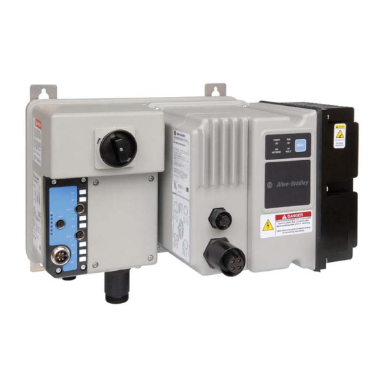
Installation and Wiring Dimensions for Bulletin 280G/281G Dimensions are shown in millimeters (inches). Dimensions are not intended to be used for manufacturing purposes. All dimensions are subject to change. Figure 2.1 Dimensions for IP67/NEMA Type 4 with ArmorConnect Connectivity... - Page 23 Installation and Wiring Figure 2.2 Bulletin 280G/281G ArmorStart® with DeviceNet™ Communication Protocol Local Disconnect LED Status Indication 6 Inputs (Micro/M12) DeviceNet Connection (Mini/M18) Motor Control Power 3-Phase Power Control Brake Connection Receptacle Ground Terminal Receptacle...
-
Page 24: Bulletin 284G
Installation and Wiring Dimensions for Bulletin 284G Dimensions are shown in millimeters (inches). Dimensions are not intended to be used for manufacturing purposes. All dimensions are subject to change. Figure 2.3 Dimensions for 2 Hp (1.5 kW) and below @ 460V AC, IP67/NEMA Type 4 with ArmorConnect connectivity... - Page 25 Installation and Wiring Dimensions for Bulletin 284G, Dimensions are shown in millimeters (inches). Dimensions are not intended to be used for manufacturing purposes. All dimensions are Continued subject to change. Figure 2.4 Dimensions for 3 Hp (2.2 kW) and above @ 460V AC, IP67/NEMA Type 4 with ArmorConnect connectivity...
-
Page 26: Bulletin 1000
Installation and Wiring Dimensions for Bulletin 1000 Dimensions are shown in millimeters (inches). Dimensions are not intended to be used for manufacturing purposes. All dimensions are subject to change. Figure 2.5 Dimensions for 7.5 Hp (5.5 kW) and 10 Hp (7.5 kW) @ 460V AC, IP67/NEMA Type 4 with ArmorConnect Connectivity... - Page 27 Installation and Wiring Dimensions for Bulletin 1000, Dimensions are shown in millimeters (inches). Dimensions are not intended to be used for manufacturing purposes. All dimensions are Continued subject to change. Figure 2.6 Dimensions for 15 Hp (11 kW) @ 460V AC, IP67/NEMA Type 4 with ArmorConnect Connectivity...
- Page 28 2-10 Installation and Wiring Figure 2.7 Bulletin 284G ArmorStart Local Disconnect LED Status Indication 6 Inputs (Micro/M12) Control Brake Connector DeviceNet Connection (Mini/M18) Motor Dynamic Control Power 3-Phase Ground Connector Brake Connector Receptacle Receptacle Terminal...
- Page 29 Installation and Wiring 2-11 Figure 2.8 Bulletin 1000 ArmorStart...
- Page 30 2-12 Installation and Wiring Figure 2.9 Bulletin 1000 ArmorStart...
-
Page 31: Ground Wiring
Installation and Wiring 2-13 Wiring Power, Control, and Ground Wiring Table 2.1 provides the power, control, safety inputs, and ground wire capacities, and the tightening torque requirements. The power, control, ground, and safety monitor terminals will accept a maximum of two wires per terminal. Table 2.1 Power, Control, Safety Input, Ground Wire Size, and Torque Specifications... -
Page 32: Terminal Designations
2-14 Installation and Wiring Terminal Designations for Bulletins As shown in the next figure, the ArmorStart Distributed Motor Controller contains terminals for power, control, and ground wiring. Access can be 280G, 281G, and 284G gained by removing the terminal access cover plate. Figure 2.10 ArmorStart Power, Control and Terminals Table 2.2 Power, Control, and Ground Terminal Designations... -
Page 33: Bulletin 280G Safety Product
Installation and Wiring 2-15 Dimensions for Bulletin 280G Dimensions are shown in millimeters (inches). Dimensions are not intended to be used for manufacturing purposes. All dimensions are Safety Product subject to change. Figure 2.11 Dimensions for Bulletin 280G Safety Product... -
Page 34: Bulletin 281G Safety Product
2-16 Installation and Wiring Dimensions for Bulletin 281G Dimensions are shown in millimeters (inches). Dimensions are not intended to be used for manufacturing purposes. All dimensions are Safety Product subject to change. Figure 2.12 Dimensions for Bulletin 281G Safety Product... -
Page 35: Bulletin 284G Safety Product
Installation and Wiring 2-17 Dimensions for Bulletin 284G Dimensions are shown in millimeters (inches). Dimensions are not intended to be used for manufacturing purposes. All dimensions are Safety Product subject to change. Figure 2.13 Dimensions for 2 Hp (1.5 kW) and below @ 460V AC, IP67/NEMA Type 4 with ArmorConnect connectivity... - Page 36 2-18 Installation and Wiring Dimensions for Bulletin 284G Dimensions are shown in millimeters (inches). Dimensions are not intended to be used for manufacturing purposes. All dimensions are Safety Product, Continued subject to change. Figure 2.14 Dimensions for 3 Hp (2.2 kW) and 5 Hp (3.0 kW) and below @ 460V AC, IP67/NEMA Type 4 with ArmorConnect connectivity...
-
Page 37: Bulletin 1000 Safety Product
Installation and Wiring 2-19 Dimensions for Bulletin 1000 Dimensions are shown in millimeters (inches). Dimensions are not intended to be used for manufacturing purposes. All dimensions are Safety Product subject to change. Figure 2.15 Dimensions for 7.5 Hp (5.5 kW) and 10 Hp (7.5 kW) @ 460V AC, IP67/NEMA Type 4 with ArmorConnect Connectivity... - Page 38 2-20 Installation and Wiring Dimensions for Bulletin 1000 Dimensions are shown in millimeters (inches). Dimensions are not intended to be used for manufacturing purposes. All dimensions are Safety Product, Continued subject to change. Figure 2.16 Dimensions for 15 Hp @ 460V AC, IP67/NEMA Type 4 with ArmorConnect Connectivity...
- Page 39 Installation and Wiring 2-21 Figure 2.17 Bulletin 280G Safety ArmorStart Local Disconnect LED Status Indication 6 Inputs (Micro/M12) DeviceNet Connection (Mini/M18) A1/A2 Motor 3-Phase Power Control Brake Connection Control Power Receptacle Receptacle...
- Page 40 2-22 Installation and Wiring Figure 2.18 Bulletin 281G Safety ArmorStart Local Disconnect LED Status Indication 6 Inputs (Micro/M12) DeviceNet Connection (Mini/M18) Control Brake Motor A1/A2 3-Phase Power Connection Receptacle Control Power...
- Page 41 Installation and Wiring 2-23 Figure 2.19 Bulletin 284G Safety ArmorStart Local Disconnect LED Status Indication 6 Inputs (Micro/M12) DeviceNet Connection (Mini/M18) Control Brake A1/A2 Motor Dynamic Brake Connection Control Power 3-Phase Power Receptacle...
- Page 42 2-24 Installation and Wiring Figure 2.20 Bulletin 1000 Safety ArmorStart...
- Page 43 Installation and Wiring 2-25 Figure 2.21 Bulletin 1000 ArmorStart...
-
Page 44: Safety Terminal Designations
2-26 Installation and Wiring Safety Terminal Designations As shown in the next figure, the ArmorStart Distributed Motor Controller contains terminals for power, safety I/O inputs, control, and ground wiring. Access can be gained by removing the terminal access cover plate. Figure 2.22 Bulletin 280G ArmorStart Safety Power, Control and Terminals Table 2.3 Power, Control, Safety Monitor, and Ground Terminal Designations... - Page 45 Installation and Wiring 2-27 Safety Terminal Designations, As shown in the next figure, the ArmorStart Distributed Motor Controller contains terminals for power, safety I/O inputs, control, and ground wiring. Continued Access can be gained by removing the terminal access cover plate. Figure 2.23 Bulletin 281G ArmorStart Safety Power, Control and Terminals Table 2.4 Power, Control, Safety Monitor, and Ground Terminal Designations...
- Page 46 2-28 Installation and Wiring Safety Terminal Designations, As shown in the next figure, the ArmorStart Distributed Motor Controller contains terminals for power, safety I/O inputs, control, and ground wiring. Continued Access can be gained by removing the terminal access cover plate. Figure 2.24 ArmorStart Safety 2 Hp Power, Control and Terminals Table 2.5 Power, Control, Safety Monitor, and Ground Terminal Designations...
-
Page 47: Armorconnect Power Media
Installation and Wiring 2-29 ArmorConnect Power Media Description The ArmorConnect power media offers both three-phase and control power cable system of cord sets, patch cords, receptacles, tees, reducers and accessories to be utilized with the ArmorStart Distributed Motor Controller. These cable system components allow quick connection of ArmorStart Distributed Motor Controllers, there by reducing installation time. - Page 48 2-30 Installation and Wiring Figure 2.26 Control Power Media System Overview Enclosure 1606-XLSDNET4 DeviceNet Power Supply RESET RESET ➏ Control Power Media Patchcords - PatchCord cable with integral female or male connector on each end Example Part Number: 889N-F3AFNU-*F ➐ Control Power Tees - The Control Power tee (Part Number: 898N-33PB-N4KF) is used with a patchcord to connect to the ArmorStart Distributed Motor Controller.
-
Page 49: Armorstart With Armorconnect Connectivity
Installation and Wiring 2-31 ArmorStart with ArmorConnect Connectivity Ground Three-Phase Control Power Terminal Power Receptacle Receptacle Terminal Designations Terminal Description Color Code Designations A1 (+) Control Power Input Black A2 (-) Control Power Common White Ground Green/Yellow 1/L1 Line Power - Phase A Black 3/L2 Line Power - Phase B... -
Page 50: Terminal Designations
2-32 Installation and Wiring ArmorStart Safety with ArmorConnect Connectivity Three-Phase Ground A1/A2 -24V DC Safety Monitor 120V AC Terminal Power Control Power rm Aux. Powr Input from Recepale 1732DS Safety 1732DS Safey Conto Brake I/O Module Outu I/O Module Inpt Terminal Designations Terminal Description... -
Page 51: Branch Circuit Protection Requirements For Armorconnect Three-Phase Power Media
Installation and Wiring 2-33 Branch Circuit Protection Requirements for ArmorConnect Three-Phase Power Media When using ArmorConnect three-phase power media, fuses can be used for the motor branch circuit protective device, for the group motor installations. The following fuse types are recommended: Class CC, T, or J type fuses. -
Page 52: Devicenet Network Installation
2-34 Installation and Wiring In industrial establishments where the conditions of maintenance and supervision ensure that only qualified persons service the installation, and where the exposed cable is continuously supported and protected against physical damage using mechanical protection, such as struts, angles, or channels, Type TC tray cable that complies with the crush and impact requirements of Type MC (Metal Clad) cable and is identified for such use with the marking Type TC-ER (Exposed... -
Page 53: Electromagnetic Compatibility (Emc)
Installation and Wiring 2-35 Electromagnetic Compatibility The following guidelines are provided for EMC installation compliance. (EMC) General Notes (Bulletin 284G only) • The motor Cable should be kept as short as possible in order to avoid electromagnetic emission as well as capacitive currents •... - Page 54 2-36 Installation and Wiring Notes:...
-
Page 55: Introduction
Chapter Bulletin 280G/281G Programmable Parameters Introduction This chapter describes each programmable parameter and its function. Parameter Programming Each Distributed Motor Controller type will have a common set of parameters followed by a set of parameters that pertain to the individual starter type. Refer to Chapter 5, DeviceNet™... -
Page 56: Parameter Group Listing
Bulletin 280G/281G Programmable Parameters Parameter Group Listing The Bulletin 280G/281G ArmorStart contains eight parameter groups. The parameters shown in the DeviceLogix, DeviceNet, Starter Protection, User I/O, Misc. Parameter, ZIP Parameters, Starter Display and Starter Setup, are discussed in this chapter. Table 3.1 Parameter Group Listing Starter... - Page 57 Bulletin 280G/281G Programmable Parameters Function — — — — — Input 0 — — — — — Input 1 — — — — — Input 2 — — — — — Input 3 — — — — — Input 4 —...
- Page 58 Bulletin 280G/281G Programmable Parameters Function 14 13 12 11 10 — — — — — — — — — — — — — — Net Output 0 — — — — — — — — — — — — — —...
- Page 59 Bulletin 280G/281G Programmable Parameters Parameter Number Starter Status Access Rule This parameter provides the Data Type WORD status of the starter Group DeviceLogix Units — Minimum Value Maximum Value 16383 Default Value Function 13 12 11 10 — — — — — — — — — — — — — Tripped —...
- Page 60 Bulletin 280G/281G Programmable Parameters Function: 15 14 13 12 11 10 9 — — — — — — — — — — — — — — — X Explicit Connection — — — — — — — — — — — — — — X — I/O Connection —...
-
Page 61: Devicenet Group
Bulletin 280G/281G Programmable Parameters Parameter Number Comm Override Access Rule GET/SET This parameter allows for local Data Type BOOL logic to override the absence of Group DeviceLogix an I/O connection Units — 0 = Disable 1 = Enable Minimum Value Maximum Value Default Value DeviceNet Group... - Page 62 Bulletin 280G/281G Programmable Parameters Parameter Number Prod Assy Word 0 Access Rule GET/SET This parameter is used to build Data Type USINT bytes 0-1 for produced assembly Group DeviceNet Units — Minimum Value Maximum Value Default Value Parameter Number Produced Assy Word 1 Access Rule GET/SET This parameter is used to build...
- Page 63 Bulletin 280G/281G Programmable Parameters Parameter Number Produced I/O Size Access Rule This parameter reflects the Data Type USINT produced I/O data size in bytes. Group DeviceNet Units — Minimum Value Maximum Value Default Value Parameter Number Starter COS Mask Access Rule GET/SET This parameter allows the Data Type...
-
Page 64: Starter Protection Group
3-10 Bulletin 280G/281G Programmable Parameters Parameter Number Net Out COS Mask Access Rule GET/SET This parameter sets the bits that Data Type WORD will trigger a COS message when Group DeviceNet network outputs change state. Units — Minimum Value Maximum Value 32767 Default Value Function... - Page 65 Bulletin 280G/281G Programmable Parameters 3-11 Parameter Number PrFlt Reset Mode Access Rule GET/SET This parameter configures the Data Type BOOL Protection Fault reset mode. Group Starter Protection Units — 0= Manual 1= Automatic Minimum Value Maximum Value Default Value Parameter Number Pr Fault Enable Access Rule GET/SET...
- Page 66 3-12 Bulletin 280G/281G Programmable Parameters Parameter Number StrtrDN FltState Access Rule GET/SET This parameter in conjunction Data Type BOOL with Parameter 27 defines how Group Starter Protection the starter will respond when a Units — DeviceNet fault occurs. When set to “1”, hold to last state occurs.
- Page 67 Bulletin 280G/281G Programmable Parameters 3-13 Last PR Fault Parameter Number 0 = None 1 = Hardware Short Circuit Access Rule 2 = Software Short Circuit 3 = Motor Overload 4 = Reserved 5 = Phase Loss Data Type UINT 6 – 12 = Reserved 13 = Control Power Loss 14 = Control Power Fuse Group...
-
Page 68: User I/O
3-14 Bulletin 280G/281G Programmable Parameters User I/O Parameter Number Off-to-On Delay Access Rule GET/SET This parameter allows the Data Type UINT installer to program a time Group User I/O duration before an input is Units reported “ON” Minimum Value Maximum Value 65.000 Default Value Parameter Number... - Page 69 Bulletin 280G/281G Programmable Parameters 3-15 Parameter Number Set to Defaults Access Rule GET/SET This parameter if set to 1 will set Data Type BOOL the device to the factory defaults Group Misc. Units — 0=No Operation 1=Set to Defaults Minimum Value Maximum Value Default Value Parameter Number...
-
Page 70: Zip Parameters
3-16 Bulletin 280G/281G Programmable Parameters Parameter Number Starter Option Access Rule Bit 0 = HOA Keypad Data Type WORD Bit 1 = Safety Monitor Group Misc. Bit 2 = Source Brake Bits 4-15 = Reserved Units — MinimumValue Maximum Value 66535 Default Value —... - Page 71 Bulletin 280G/281G Programmable Parameters 3-17 Parameter Number Zone #2 MAC ID Access Rule GET/SET The node address of the device Data Type USINT whose data is to be consumed Group ZIP Parameters for zone 2 Units — MinimumValue Maximum Value Default Value Parameter Number Zone #3 MAC ID...
- Page 72 3-18 Bulletin 280G/281G Programmable Parameters Parameter Number Zone #3 Health Access Rule Read Only consumed connection Data Type BOOL status for zone 3 Group ZIP Parameters Units — 0 = Healthy 1 = Unhealthy MinimumValue Maximum Value Default Value Parameter Number Zone #4 Health Access Rule Read Only consumed connection...
- Page 73 Bulletin 280G/281G Programmable Parameters 3-19 Parameter Number Zone #4 Mask Access Rule GET/SET Bit enumerated consumed data Data Type BYTE mask for zone 4. Each bit Group ZIP Parameters represents a byte in consumed Units — data up to 8 bytes in length. If a mask bit is set, the MinimumValue corresponding consumed data...
- Page 74 3-20 Bulletin 280G/281G Programmable Parameters Parameter Number Zone #1 EPR Access Rule GET/SET The Expected Packet Rate in Data Type UINT msec. for the zone 1 consuming Group ZIP Parameters connection. If consumed data is Units msec not received in 4 times this value, the zone connection will MinimumValue time out and “Zone #1 Health”...
- Page 75 Bulletin 280G/281G Programmable Parameters 3-21 Zone #1 Control Parameter Number Zone 1 Control Word. Default Access Rule GET/SET Bit 0 and Bit 1 set, all other bits clear. Data Type BYTE Bit0=Security Enable 1=Enable data security Group ZIP Parameters Bit1=COS Cnxn 1=Consume DNet Group 2 COS messages Units...
- Page 76 3-22 Bulletin 280G/281G Programmable Parameters Zone #4 Control Parameter Number Zone 3 Control Word. Default Access Rule GET/SET Bit 0 and Bit 1 set, all other bits clear. Data Type BYTE Bit0=Security Enable 1=Enable data security Group ZIP Parameters Bit1=COS Cnxn 1=Consume DNet Group 2 COS messages Units...
-
Page 77: Starter Display
Bulletin 280G/281G Programmable Parameters 3-23 Parameter Number Zone #4 KEY Access Rule GET/SET When the “Security Enable” bit Data Type UINT for zone 4 is enabled, this value Group ZIP Parameters must match the value of the Units — Device Value Key parameter in the device whose data is being MinimumValue consumed for zone 4... -
Page 78: Starter Setup
3-24 Bulletin 280G/281G Programmable Parameters Parameter Number Phase C Current Access Rule GET/SET This parameter provides the Data Type current of Phase C measured in Group Starter Display increments of 1/10 of an Units xx.x Amps ampere Minimum Value Maximum Value 32767 Default Value Parameter Number... - Page 79 Bulletin 280G/281G Programmable Parameters 3-25 Parameter Number Overload Class Access Rule GET/SET This parameter allows the Data Type USINT installer to select the overload Group Starter Setup class Units xx.x Amps 1= Overload Class 10 Minimum Value 2= Overload Class 15 Maximum Value 3= Overload Class 20 Default Value...
- Page 80 3-26 Bulletin 280G/281G Programmable Parameters Notes...
-
Page 81: Parameter Programming
Chapter Bulletin 284G Programmable Parameters for Sensorless Vector Controllers This chapter describes each programmable parameter and its function for Bulletin 284G Sensorless Vector Controllers. Parameter Programming Each Distributed Motor Controller type will have a common set of parameters followed by a set of parameters that pertain to the individual starter type. -
Page 82: Parameter Group Listing
Bulletin 284G Programmable Parameters for Sensorless Vector Controllers Parameter Group Listing The Bulletin 284G ArmorStart contains ten parameter groups. The parameters shown in the DeviceLogix™, DeviceNet , Starter Protection , User I/O , Misc. Parameter , Drive DeviceNet , Display Group, ZIP Parameters, Basic Program, and Advanced Program will be discussed in this chapter. -
Page 83: Devicelogix Group
Bulletin 284G Programmable Parameters for Sensorless Vector Controllers DeviceLogix Group This parameter is not available with the Bulletin 284A. Parameter Number Hdw Inputs This parameter provides status of hardware inputs. Access Rule Data Type WORD Group DeviceLogix Units — Minimum Value Maximum Value Default Value Function... - Page 84 Bulletin 284G Programmable Parameters for Sensorless Vector Controllers Parameter Number Network Outputs This parameter provides status of network outputs. Access Rule Data Type WORD Group DeviceLogix Units — Minimum Value Maximum Value 32767 Default Value Function — — — — —...
- Page 85 Bulletin 284G Programmable Parameters for Sensorless Vector Controllers Parameter Number Trip Status This parameter provides trip identification. Access Rule Data Type WORD Group DeviceLogix Units — Minimum Value Maximum Value 65535 Default Value Function — — — — — — —...
- Page 86 Bulletin 284G Programmable Parameters for Sensorless Vector Controllers Parameter Number Starter Status This parameter provides the status of the starter. Access Rule Data Type WORD Group DeviceLogix Units — Minimum Value Maximum Value 65535 Default Value Function — — — —...
- Page 87 Bulletin 284G Programmable Parameters for Sensorless Vector Controllers Parameter Number Dnet Status This parameter provides status of the DeviceNet connection. Access Rule Data Type WORD Group DeviceLogix Units — Minimum Value Maximum Value Default Value Function — — — — —...
-
Page 88: Devicenet Group
Bulletin 284G Programmable Parameters for Sensorless Vector Controllers Parameter Number Network Override This parameter allows for the local logic to override a Network fault. Access Rule GET/SET 0 = Disable Data Type BOOL 1 = Enable Group DeviceLogix Units — Minimum Value Maximum Value Default Value... - Page 89 Bulletin 284G Programmable Parameters for Sensorless Vector Controllers Parameter Number Prod Assy Word 0 This parameter is used to build bytes 0-1 for produced assembly 120. Access Rule GET/SET Data Type USINT Group DeviceNet Units — Minimum Value Maximum Value Default Value Parameter Number Produced Assy Word 1...
- Page 90 4-10 Bulletin 284G Programmable Parameters for Sensorless Vector Controllers Parameter Number Produced I/O Size This parameter maps to the Scanners Rx Size. Access Rule Data Type USINT Group DeviceNet Units — Minimum Value Maximum Value Default Value Parameter Number Starter COS Mask This parameter allows the installer to define the change-of-state conditions that will Access Rule GET/SET...
- Page 91 Bulletin 284G Programmable Parameters for Sensorless Vector Controllers 4-11 Net Out COS Mask Parameter Number This parameter sets the bit that will trigger a COS message on the network output. Access Rule GET/SET Data Type WORD Group DeviceNet Units — Minimum Value Maximum Value 32767...
-
Page 92: Starter Protection Group
4-12 Bulletin 284G Programmable Parameters for Sensorless Vector Controllers Starter Protection Group Parameter Number Breaker Type This parameter identifies the Bulletin 140M used in this product. Access Rule 0 = 140M-D8N-C10 Data Type BOOL 1 = 140M-D8N-C25 Group Starter Protection Units —... - Page 93 Bulletin 284G Programmable Parameters for Sensorless Vector Controllers 4-13 Parameter Number Pr Fault Reset This parameter resets the Protection Fault on a transition 0 > 1. Access Rule GET/SET Data Type BOOL Group Starter Protection Units — Minimum Value Maximum Value Default Value Parameter Number StrtrDN FltState...
- Page 94 4-14 Bulletin 284G Programmable Parameters for Sensorless Vector Controllers Last PR Fault Parameter Number 1 =Hdw Short Ckt 2 = Reserved 3 =Motor Overload (PF Fault Code 7) 4 =Drive Overload (PF Fault Code 64) Access Rule 5 = Phase U to Gnd (PF Fault Code 38) 6 = Phase V to Gnd (PF Fault Code 39) 7 = Phase W to Gnd (PF Fault Code 40) 8 = Phase UV Short (PF4 Fault Code 41)
-
Page 95: User I/O
Bulletin 284G Programmable Parameters for Sensorless Vector Controllers 4-15 User I/O Group Parameter Number Off-to-On Delay This parameter allows the installer to program a time duration before being reported Access Rule GET/SET Data Type UINT Group User I/O Units Minimum Value Maximum Value 65.000 Default Value... -
Page 96: Miscellaneous Group
4-16 Bulletin 284G Programmable Parameters for Sensorless Vector Controllers Miscellaneous Group Parameter Number Keypad Mode This parameter selects if the keypad operation is maintained or momentary. Access Rule GET/SET 0 = Maintained Data Type BOOL 1 = Momentary Group Misc. Units —... -
Page 97: Bits 3-15 Reserved
Bulletin 284G Programmable Parameters for Sensorless Vector Controllers 4-17 Parameter Number Wiring Options Access Rule Bit 0 = Conduit Data Type WORD Bit 1 = Round Media Group Misc. Bits 2 = 28xG Units — Bits 3-15 = Reserved Minimum Value Maximum Value Default Value Parameter Number... -
Page 98: Drive Devicenet Group
4-18 Bulletin 284G Programmable Parameters for Sensorless Vector Controllers Drive DeviceNet Group Parameter Number Drive Control This parameter provides the status of drive parameters. Access Rule Data Type WORD Group Drive DeviceNet Units — Minimum Value Maximum Value 4095 Default Value Function —... -
Page 99: Parameter Number
Bulletin 284G Programmable Parameters for Sensorless Vector Controllers 4-19 Parameter Number Drvin DNFltState This parameter, in conjunction with Parameter 52, defines how the Drive Digital Access Rule GET/SET Inputs 1…4 will respond when a DeviceNet fault occurs. When set to 1, Drive Data Type BOOL Digital Inputs 1…4 hold to last state occurs. -
Page 100: Display Group
4-20 Bulletin 284G Programmable Parameters for Sensorless Vector Controllers Display Group Parameter Number Output Freq Output frequency present at T1, T2, T3. Related Parameters 102, 110, 134, 135, 138 Access Rule Data Type UINT Group Display Group Units 0.1 Hz Minimum Value Maximum Value 400.0 Hz... - Page 101 Bulletin 284G Programmable Parameters for Sensorless Vector Controllers 4-21 Parameter Number Drive Status Present operating condition of the drive. Related Parameter Bit 0 = running Access Rule Bit 1 = Forward Data Type Byte Bit 2 = Accelerating Group Display Group Bit 3 = Decelerating Units —...
-
Page 102: Default Value
4-22 Bulletin 284G Programmable Parameters for Sensorless Vector Controllers Parameter Number Control Source Displays the source of the Start Command and Speed Reference. 136, 138, 151…154 (Digital Valid Start Commands for the Bulletin 284G ArmorStart are the following: Inx Sel) must be set to 4, 169, 2 = 2-wire Related Parameters 170…177 (Preset Freq X),... - Page 103 Display Group Units 0.01 Minimum Value 1.00 Maximum Value 99.99 Default Value Read Only Parameter Number Drive Type Used by Rockwell Automation field service personnel. Access Rule Data Type UINT Group Display Group Units Minimum Value 1001 Maximum Value 9999...
- Page 104 4-24 Bulletin 284G Programmable Parameters for Sensorless Vector Controllers Parameter Number Output Power The output power present at T1, T2, and T3. Access Rule Data Type UINT Group Display Group Units Minimum Value 0.00 Maximum Value Drive rated power X 2 Default Value Read Only Parameter Number...
-
Page 105: Basic Program Group
Bulletin 284G Programmable Parameters for Sensorless Vector Controllers 4-25 Parameter Number Stp Logic Status When Parameter 138 (Speed Reference) is set to 6 Stp Logic, this parameter will Access Rule display the current step of step logic as defined by Parameters 240…247 (Stp Data Type UINT Logic X). - Page 106 4-26 Bulletin 284G Programmable Parameters for Sensorless Vector Controllers Parameter Number Motor OL Current Set to the maximum allowable current. The drive fault on an F7 Motor Over load if 155, 158, 161, 189, 190, 198, Related Parameter the value of this parameter is exceeded by 150% for 60 seconds. 214, 218 Access Rule GET/SET...
- Page 107 Bulletin 284G Programmable Parameters for Sensorless Vector Controllers 4-27 Stop Mode Parameter Number Valid Stop Mode for the Bulletin 284G ArmorStart are the following: 136, 180, 181, 182, 205, 260, 0 = Ramp, CF Ramp to Stop. Stop command clears active fault. Related Parameters 1 = Coast, CF Coast to Stop.
-
Page 108: Advanced Program Group
4-28 Bulletin 284G Programmable Parameters for Sensorless Vector Controllers Parameter Number Decel Time 1 Sets the rate of deceleration for all speed decreases. 138, 139, 151, 152, 153, 154, Related Parameters 168, 170…173, 174…177, Maximum Freq ------------------------------------- - Decel Rate and 240…247 Decel Time Access Rule... - Page 109 Bulletin 284G Programmable Parameters for Sensorless Vector Controllers 4-29 Table 4.2 Digital Inputs Options Options Description Not Used Terminal has no function but can be read over network communication via Parameter 114 (Dig In Status). • When active, Parameter 167 (Accel Time 2) and Parameter 168 (Decel Time 2) are used for all ramp rates Acc &...
- Page 110 4-30 Bulletin 284G Programmable Parameters for Sensorless Vector Controllers Parameter Number 155 (Relay Out Sel) Sets the condition that changes the state of the output relay contacts. 133, 156, 192, 240…247, Related Parameters 250…257, 260, 261 Access Rule GET/SET Data Type UINT Group Advanced Program Group...
- Page 111 Bulletin 284G Programmable Parameters for Sensorless Vector Controllers 4-31 Relay Out Level Parameter Number Sets the trip point for the digital output relay if the value of Parameter 155 (Relay Related Parameters 155, 158, 161 Out Sel) is 6, 7, 8, 10, 16, 17, 18, or 20. Access Rule GET/SET Parameters 155 Setting...
- Page 112 4-32 Bulletin 284G Programmable Parameters for Sensorless Vector Controllers Options Description StpLogic Out Drive enters Step Logic step with Digit 3 of Command Word (Parameters 240…247). Timer has reached value set in Parameter 159 (Opto Out 1 Level) or Parameter 162 (Opto Output 2 Level). Use Timer Out Parameter 159 or 162 to set threshold.
- Page 113 Bulletin 284G Programmable Parameters for Sensorless Vector Controllers 4-33 Parameter Number Analog Out Sel Sets the analog output signal (0…10V). The output is used to provide a signal that is Related Parameters 135, 166 proportional to several drives Access Rule GET/SET Data Type UINT...
- Page 114 4-34 Bulletin 284G Programmable Parameters for Sensorless Vector Controllers Parameter Number Accel Time 2 When active, sets the rate of acceleration for all speed increases except for jog. 139, 151, 152, 153, 154, Related Parameters 170…173, 174…177, Maximum Freq ------------------------------------- - Accel Rate Accel Time 240…247...
- Page 115 Bulletin 284G Programmable Parameters for Sensorless Vector Controllers 4-35 170 (Preset Freq 0) ➊ Parameter Number 170…173, 174…177 Related Parameters 138, 139, 140, 151, 152, 152, 171 (Preset Freq 1) 153, 167, 168, 240…247, 172 (Preset Freq 2) 250…257 173 (Preset Freq 3) 174 (Preset Freq 4) Access Rule GET/SET...
- Page 116 4-36 Bulletin 284G Programmable Parameters for Sensorless Vector Controllers Parameter Number Jog Accel/Decel Sets the acceleration and deceleration time when a jog command is issued. Related Parameters 178, 151, 152, 153, 154 Access Rule GET/SET Data Type UINT Group Advanced Program Group Units 0.1 sec Minimum Value...
- Page 117 Bulletin 284G Programmable Parameters for Sensorless Vector Controllers 4-37 Parameter Number DB Resistor Sel Related Parameters Stop drive before changing this parameter. Access Rule GET/SET Enables/disables external dynamic braking. Data Type UINT Group Advanced Program Group Setting Min./Max. Units Disabled Minimum Value Normal RA Res (5% Duty Cycle) Maximum Value...
-
Page 118: Figure 4.1
4-38 Bulletin 284G Programmable Parameters for Sensorless Vector Controllers Table 4.6 Boost Select Options Options Description Custom V/Hz 30.0, VT Variable Torque (Typical fan/pump 35.0, VT curves) 40.0, VT 45.0, VT 0.0 no IR 2.5, CT (Default for 5 Hp/4.0 kW Drive) 5.0, CT Default 7.5,CT Constant Torque... - Page 119 Bulletin 284G Programmable Parameters for Sensorless Vector Controllers 4-39 Parameter Number Start Boost Sets the boost voltage (% of Parameter 131 [Motor NP Volts]) and redefines the Volts 131, 132, 134, 135, 184, 186, Related Parameters per Hz curve when Parameter 184 (Boost Select) = 0 Custom V/Hz and Parameter 187, 188, 225 225 (Torque Perf Mode) = 0V/Hz.
- Page 120 4-40 Bulletin 284G Programmable Parameters for Sensorless Vector Controllers Parameter Number Brake Voltage Sets the frequency where brake voltage is applied when Parameter 184 (Boost 131, 132, 134, 135, 184, 185, Related Parameters Select) = 0 Custom V/Hz and Parameter 225 (Torque Perf Mode) = 0V/Hz. 187, 188, 225 Access Rule GET/SET...
- Page 121 Bulletin 284G Programmable Parameters for Sensorless Vector Controllers 4-41 Parameter Number Motor OL Select Drive provides Class 10 motor overload protection. Setting 0…2 select the derating Related Parameters 132, 133 factor for I t overload function. Access Rule GET/SET 0 = No Derate Data Type UINT 1 = Min.
-
Page 122: Clear An Overvoltage, Undervoltage, Or Heatsink Ovrtmp Fault Without Restarting The Drive
4-42 Bulletin 284G Programmable Parameters for Sensorless Vector Controllers Parameter Number Auto Rstrt Tries Set the maximum number of times the drive attempts to reset a fault and restart. Related Parameter 155, 158, 161, 193 Access Rule GET/SET Data Type UINT Group Advanced Program Group... -
Page 123: Related Parameters
Bulletin 284G Programmable Parameters for Sensorless Vector Controllers 4-43 Parameter Number Start at PowerUp Related Parameters Stop drive before changing this parameter. Access Rule GET/SET Data Type UINT Enables/disables a feature that allows a Start or Run command to automatically Group Advanced Program Group cause the drive to resume running at command speed after the drive input is... -
Page 124: Minimum Value Maximum Value
1 = Locked Group Advanced Program Group Units — Minimum Value Maximum Value Default Value Parameter Number Testpoint Sel Used by Rockwell Automation field service personnel. Related Parameters Access Rule GET/SET Data Type UINT Group Advanced Program Group Units 1 Hex... -
Page 125: Default Value
Bulletin 284G Programmable Parameters for Sensorless Vector Controllers 4-45 Comm Data Rate This parameter is not available for use with the ArmorStart Distributed Motor Parameter Number Controller. CommNode Addr This parameter is not available for use with the ArmorStart Distributed Motor Parameter Number Controller. - Page 126 4-46 Bulletin 284G Programmable Parameters for Sensorless Vector Controllers Parameter Number Anlg In 0…10V Lo Related Parameter 121, 134, 138, 222 Stop drive before changing this parameter. Access Rule GET/SET Data Type UINT Sets the analog input level that corresponds to parameter 134 (Minimum Freq) if a Group Advanced Program Group 0…10V input is used by parameter 138 (Speed Reference)
- Page 127 Bulletin 284G Programmable Parameters for Sensorless Vector Controllers 4-47 Parameter Number Slip Hertz @ FLA Compensates for the inherent slip in an induction motor. This frequency is added to Related Parameter the commanded output frequency based on motor current. Access Rule GET/SET Data Type UINT...
- Page 128 4-48 Bulletin 284G Programmable Parameters for Sensorless Vector Controllers Parameter Number Current Limit 2 Maximum output current allowed before current limiting occurs. This parameter is Related Parameters 133, 151, 152, 153, 154, 189 only active if Parameters 151, 152, 153, and 154 (Digital Inx Sel) is set to 25 Access Rule GET/SET Current Lmt2 and is active.
- Page 129 Bulletin 284G Programmable Parameters for Sensorless Vector Controllers 4-49 Parameter Number Stall Fault Time Sets for the fault time that the drive will remain in stall mode before a fault is issued. Access Rule GET/SET 0 = 60 sec (Default) Data Type UINT 1 = 120 sec...
- Page 130 4-50 Bulletin 284G Programmable Parameters for Sensorless Vector Controllers Parameter Number Var PWM Disable Related Parameters Stop drive before changing this parameter. Access Rule GET/SET Data Type UINT Enables/disables a feature that varies the carrier frequency for the PWM output Group Advanced Program Group waveform defined by Parameter 191 (PWM Frequency).
- Page 131 Bulletin 284G Programmable Parameters for Sensorless Vector Controllers 4-51 Autotune Parameter Number Stop drive before changing this parameter. Related Parameters 225, 226, 228, 229 Provides an automatic method for setting Parameter 228 (IR Voltage Drop) and Parameter 229 (Flux Current Ref), which affect sensorless vector performance. Access Rule GET/SET Parameter 226 (Motor NP FLA) must be set to the motor nameplate full load amps...
- Page 132 4-52 Bulletin 284G Programmable Parameters for Sensorless Vector Controllers Parameter Number IR Voltage Drop Value of volts dropped across the resistance of the motor stator. Related Parameters Access Rule GET/SET Data Type UINT Group Advanced Program Group Units 0.1V AC Minimum Value Maximum Value Default Value...
- Page 133 Bulletin 284G Programmable Parameters for Sensorless Vector Controllers 4-53 Parameter Number PID Feedback Sel Valid PID Feedback Sel command for the Bulletin 284G ArmorStart is the following; Access Rule GET/SET 2 = Comm Port Data Type UINT Group Advanced Program Group Units —...
- Page 134 4-54 Bulletin 284G Programmable Parameters for Sensorless Vector Controllers Parameter Number PID Deadband Sets the lower limit of the PID output. Access Rule GET/SET Data Type UINT Group Advanced Program Group Units 0.1% Minimum Value 0.0% Maximum Value 10.0% Default Value 0.0% Parameter Number PID Preload...
-
Page 135: How Step Logic Works
Bulletin 284G Programmable Parameters for Sensorless Vector Controllers 4-55 Table 4.8 Related Preset Frequency Related Step Logic Time Step Logic Parameter Parameter (Can be activated Parameter (Active when (Active when 138 = 6 Stp independent of Step Logic 240…247 Digit 0 or 1 are set Logic) Parameters) to 1, b, C, d, or E) - Page 136 4-56 Bulletin 284G Programmable Parameters for Sensorless Vector Controllers Table 4.9 Digit 3 Settings Required Accel/Decel Step Logic Commanded Setting Parameter Used Output State Direction Accel/Decel 1 Accel/Decel 1 Accel/Decel 1 No Output Accel/Decel 1 Accel/Decel 1 Accel/Decel 1 No Output Accel/Decel 2 Accel/Decel 2 Accel/Decel 2...
- Page 137 Bulletin 284G Programmable Parameters for Sensorless Vector Controllers 4-57 Parameter Number 250…257 A250 (Stp Logic Time 0) A251 (Stp Logic Time 1) 138, 155, 158, 161, Related Parameters A252 (Stp Logic Time 2) 171…177, 240…247 A253 (Stp Logic Time 3) Access Rule GET/SET A254 (Stp Logic Time 4)
- Page 138 4-58 Bulletin 284G Programmable Parameters for Sensorless Vector Controllers Parameter Number MOP Reset Sel Sets the drive to save the current MOP Reference command. Related Parameters 0 = Zero MOP Ref Access Rule Get/Set This option clamps Parameter 169 (Internal Freq) at 0.0 Hz when drive is not running. Data Type UINT 1 = Save MOP Ref (Default)
-
Page 139: Establishing A Devicenet Node Address
Chapter DeviceNet™ Commissioning This chapter refers to Bulletin 280G/281G and 284G products. Establishing a DeviceNet Node The ArmorStart® is shipped with a default node address of 63 and Autobaud enabled. Each device on a DeviceNet network must have a Address unique node address or MAC ID which can be set to a value from 0 to 63. -
Page 140: Node Commissioning Using Software
DeviceNet™ Commissioning Node Commissioning using To set the node address of the ArmorStart using software or other handheld tools, leave the hardware switches in there default position Software (99) or insure that they are set to something greater than (63). With the hardware switches set, use the software or handheld tool to change the address. -
Page 141: Building And Registering An Eds File
DeviceNet™ Commissioning Building and Registering an EDS The EDS file defines how RSNetWorx for DeviceNet will communicate to the ArmorStart. Follow the steps below to build and File register the EDS file. To register a device you must first obtain the EDS file from the following web page: http://www.ab.com/networks/eds After obtaining the files do the following: 1. - Page 142 DeviceNet™ Commissioning 5. Click the Next button. 6. The following screen will display any warning or errors if a prob- lem occurs while registering the file. If a problem occurs insure that you have the correct file and try again. Click the Next button when no errors occur.
-
Page 143: Using The Node Commissioning Tool Inside Rsnetworx For Devicenet
DeviceNet™ Commissioning 9. Click the Finish button. After a short while RSNetWorx will update your online screen by replacing the unrecognized device with the name and icon given by the EDS file you have just regis- tered. Using the Node Commissioning 1. -
Page 144: System Configuration
DeviceNet™ Commissioning 5. When the new node address has been successfully applied, the “Current Device Settings” section of the window is updated as follows. If an error occurs, check to make sure the device is prop- erly powered up and connected to the network. 6. -
Page 145: Using Automap Feature With Default Input And Output (I/O) Assemblies (Bulletin 280G/281G)
DeviceNet™ Commissioning Using Automap feature with The Automap feature available in all Rockwell Automation scanners will automatically map the information as shown below. If manual default Input and Output (I/O) mapping is not required, the information below can be used to map a Assemblies (Bulletin 280G/281G) device based on the default configuration. -
Page 146: Setting The Motor Fla And Overload Trip Class (Bulletin 280G/281G)
DeviceNet™ Commissioning Setting the Motor FLA and The product should now be configured and communicating on the network. The last step is to program the motor FLA setting Overload Trip Class (Bulletin 280G/ (parameter# 106) and overload trip class (parameter# 107). This can 281G) be accomplished by using software such as RSNetWorx for DeviceNet or another handheld DeviceNet tool. -
Page 147: Using Automap Feature With Default Input And Output (I/O) Assemblies (Bulletin 284G)
DeviceNet™ Commissioning Using Automap feature with The Automap feature available in all Rockwell Automation scanners will automatically map the information as shown below. If manual default Input and Output (I/O) mapping is not required, the information below can be used to map a Assemblies (Bulletin 284G) device based on the default configuration. -
Page 148: Setting The Motor Fla (Bulletin 284G)
5-10 DeviceNet™ Commissioning Setting the Motor FLA (Bulletin The product should now be configured and communicating on the network. The last step is to program the proper motor OL current 284G) setting (Parameter 133). This can be accomplished by using software such as RSNetWorx for DeviceNet or a handheld DeviceNet tool. -
Page 149: User Manual
DeviceNet™ Commissioning 5-11 193-DNCT Product Overview The 193-DNCT product is a handheld device that can be used to commission, configure, program, and monitor other devices on a DeviceNet™ network. In addition, the 193-DNCT can be used to upload, store, and later download complete device configurations for DeviceNet™... -
Page 150: Tools Menu
5-12 DeviceNet™ Commissioning Tools Menu The Tools Menu gives the user access to the Node Commissioning screen, a Class Instance Attribute editor, and a graphical parameter chart recorder screen. The Tools Menu is shown below: Node Commissioning Pressing Enter while the NodeComm item is selected in the Tools Menu invokes the Node Commissioning screen. -
Page 151: Logic Controller Application Example With Explicit Messaging
Chapter Explicit Messaging on DeviceNet™ Logic Controller Application This chapter is designed to demonstrate programming and explicit message examples for both the SLC™ family of programmable Example with Explicit controllers and ControlLogix® family of programmable controllers. Messaging The examples will show how to develop a program for simple control and use a simple explicit message to retrieve data that is not automatically acquired based on the input and output assembly of the device. -
Page 152: Programming The 1747-Slc
Explicit Messaging on DeviceNet™ Programming the 1747-SLC I/O Mapping The following example will utilize the Standard Distributed Motor Controller and the factory default input and output assembly of 160 and 161. Refer to Appendix B, Bulletin 280G/281G CIP Information for additional assembly formats. The default input and output assemblies are shown in the table below with the corresponding data size. -
Page 153: Explicit Messaging With Slc
Explicit Messaging on DeviceNet™ Explicit Messaging with SLC The 1747-SDN module uses the M0 and M1 file areas for data transfer. Only words 224 through 256 are used to execute the Explicit Message Request and Response function. The minimum data size for the explicit message request is 6 words and the maximum is 32 words. -
Page 154: Setting Up The Data File
Explicit Messaging on DeviceNet™ • Size: This identifies the size of the transaction body in bytes. The transaction body begins at word 3. The maximum size is 58 bytes. The Size data size is one byte. • Service: This code specifies the type of request being delivered. The Service data size is one byte. -
Page 155: Sequence Of Events
Explicit Messaging on DeviceNet™ Sequence of Events Use the following sequence of events as a guide for establishing explicit messages in your SLC ladder logic. 1. Put the explicit message request data into an integer (N) file of the SLC-500 processor. 2. - Page 156 Explicit Messaging on DeviceNet™ If a trip condition exists, momentarily setting B3:0.1 will reset the fault. B3:0.0 will need to be re-initiated to start the “run Fwd”...
- Page 157 Explicit Messaging on DeviceNet™...
-
Page 158: Programming The 1756-Controllogix
Explicit Messaging on DeviceNet™ Programming the I/O Mapping 1756-ControlLogix The following example will use the standard distributed motor controller and the factory default input and output assembly of 160 and 161. Refer to Appendix B for additional assembly formats. The default input and output assembly will again be used in the following example. -
Page 159: Explicit Messaging With Controllogix
Explicit Messaging on DeviceNet™ Explicit Messaging with The ControlLogix platform requires significantly less structure to initiate an explicit message. The explicit message Request and ControlLogix Response is configured within the MSG function. The MSG function can be found in the Input/Output tab of RSLogix 5000. Notice that in the ControlLogix program example, rung 6 is the only required logic to complete the explicit message request. - Page 160 6-10 Explicit Messaging on DeviceNet™ • Service Type The pull down menu has several options, however only the Get Attribute Single is used for this example. The Class, Instance, and Attribute define the actual information being requested. Additional configurations of these parameters can be found in Appendix B.
- Page 161 Explicit Messaging on DeviceNet™ 6-11 Figure 6.5 ControlLogix Example of Ladder Logic Program...
- Page 162 6-12 Explicit Messaging on DeviceNet™ Notes...
-
Page 163: Devicelogix Programming
Chapter Using DeviceLogix™ DeviceLogix is a stand-alone Boolean program that resides within the ArmorStart®. The program is embedded in the product software so that there is no additional module required to use this technology; RSNetWorx™ for DeviceNet™ is required to program the device. In addition to the actual programming, DeviceLogix can be configured to operate under specific situations. -
Page 164: Devicelogix Programming Example
Using DeviceLogix™ There are many reasons to use the DeviceLogix functionality, but some of the most common are listed below: • Increased system reliability • Fast update times (1 - 2 ms possible) • Improved diagnostics and reduced troubleshooting • Operation independent of PLC or Network status •... - Page 165 Using DeviceLogix™ 7. From the toolbar, Click on the “Discrete Input” button and select Input 0 from the pull-down menu. This is the remote start button based on the example I/O table. 8. Place the input to the left of the RSL function. To drop the input on the page, left click on the desired position.
- Page 166 Using DeviceLogix™ 14. From the toolbar, Click on the “Discrete Output” button and select “Run Fwd” from the pull-down menu. Run Fwd is the relay controlling the coil of the contactor. Click OK. 15. Move the cursor into the grid and place the Output to the right of the RSL function block.
-
Page 167: Armorstart Fault Bit, Status Bit, Outputs And Produced Network Bits In The Devicelogix Ladder Editor
Using DeviceLogix™ ArmorStart Fault Bit, Status Bit, All ArmorStart Distributed Motor Starters support DeviceLogix. When using the DeviceLogix ladder editor to program logic for an Outputs and Produced Network ArmorStart, the bit names that are associated with fault bits, status Bits in the DeviceLogix Ladder bits, outputs and produced network bits when using the original Editor... - Page 168 Using DeviceLogix™ 2. Bulletin 280G and 281G ArmorStart Fault Bits The screen capture below how to choose fault bits in the ladder editor. The following list contains the fault bit definitions for Bulletin 280G and 281G ArmorStart units: ArmorStart Revision 2.xxx (280G and 281G) 0 = Short Circuit 1 = Overload 2 = Phase Loss...
- Page 169 Using DeviceLogix™ 3. Bulletin 280G and 281G ArmorStart Produced Network Bits The screen capture below shows how to choose Produced Network Bits in the ladder editor. The following table contains the produced network bit definitions for Bulletin 280G and 281G ArmorStart units: ArmorStart Revision 2.xxx (280G and 281G) 0 = Net Output 0 1 = Net Output 1...
- Page 170 Using DeviceLogix™ 4. Bulletin 284G ArmorStart Status Bits The following table contains the status bit definitions for Bulletin 284G ArmorStart: Power Flex 40 Revision 2.00x (284G) 0 = Tripped 1 = Warning 2 = Running Fwd 3 = Running Rev 4 = Ready 5 = Net Ctl Status 6 = Net Ref Status...
- Page 171 Using DeviceLogix™ 5. Bulletin 284G ArmorStart Fault Bits The screen capture below shows how to choose Fault Bits in the ladder editor. The following table contains the fault bit definitions for Bulletin 284G ArmorStart: ArmorStart Revision 2.xxx (284G) 0 = Short Circuit 1 = Overload 2 = Phase Short 3 = Ground Fault...
- Page 172 7-10 Using DeviceLogix™ 6. Bulletin 284G ArmorStartProduced Network Bits The screen capture below shows how to choose Produced Network Bits in the ladder editor. The following table contains the produced network bit definitions for Bulletin 284G ArmorStart units: ArmorStart Revision 2.xxx (284G) 0 = Net Output 0 1 = Net Output 1 2 = Net Output 2...
-
Page 173: Overview
Chapter ArmorStart® ZIP Configuration Overview This chapter describes the steps necessary to configure the Zone Interlocking Parameters (ZIP) to configure peer-to-peer communication between an ArmorStart and another ZIP enabled device such as another ArmorStart or a 1977-ZCIO module. First, an overview of the ZIP parameter set is presented. - Page 174 ArmorStart® ZIP Configuration Param # Parameter Name Parameter Description AutoRun ZIP Enables ZIP data production on power up 0=Disable; 1=Enable Zone ProducedEPR The Expected Packet Rate in msec. Defines the rate of at which ZIP data is produced. Defaults to 75 msec. Zone ProducedPIT The Production Inhibit Time in msec.
-
Page 175: Data Production
ArmorStart® ZIP Configuration Data Production In a typical ZIP system, each device on the network automatically produces IO data using “Change of State” (COS) triggering. The automatic production of this COS data by an ArmorStart is enabled by setting Parameter 67 (AutoRun ZIP) to a value of 1 = Enable. Then COS data will be produced automatically when the global ZIP enable parameter (Zone Ctrl Enable, Parameter 99) is set to the value of 1 = Enable. - Page 176 ArmorStart® ZIP Configuration The “Zone Mask” parameters (parameters 78-81) select individual bytes within a consumed message for placement in the DeviceLogix Data Table. Each single bit in the mask represents a corresponding byte in the consumed message packet. For example, consider an ArmorStart that has zone 1 configured to consume data from another ArmorStart that is producing data of the following format: Instance 163 Standard Produced Starter with Network Outputs and ZIP CCV...
- Page 177 ArmorStart® ZIP Configuration ZIP 18 = Zone 1: Running Fwd ZIP 19 = Zone 1: Running Rev ZIP 20 = Zone 1: Ready ZIP 21 = Zone 1: reserved ZIP 22 = Zone 1: reserved ZIP 23 = Zone 1: reserved ZIP 24 = Zone 1: User In 1 ZIP 25 = Zone 1: User In 2 ZIP 26 = Zone 1: User In 3...
- Page 178 ArmorStart® ZIP Configuration We will configure node 10 to consume data as follows: Zone 1 data will come from node 11 Zone 2 data will come from node 12 Zone 3 data will come from node 13 Zone 4 data will come from node 14. First we must set up nodes 11-14 to “Auto Produce”...
- Page 179 ArmorStart® ZIP Configuration For the 1799-ZCIO module (shown below) this is done by setting parameter 13 “AutoRun Zip” to “Enabled”. Next we must configure data consumption for the 4 zones in the ArmorStart at node 10. First set the “Zone MacId” parameters as shown below:...
- Page 180 ArmorStart® ZIP Configuration We will leave the “Zone EPR” parameters at their default value of 75 msec. This tells our ArmorStart that if no data for a zone is consumed for a period of 300 msec (4 times the EPR), the zone connection should time out and the health status should be set to “Not Healthy”.
- Page 181 ArmorStart® ZIP Configuration We will set the “Zone Offsets as shown below. This maps zone 1 data to byte 0 of the DeviceLogix Data Table, zone 2 data to byte 2 of the DeviceLogix Data Table, zone 3 data to byte 4 of the DeviceLogix Data Table and zone 4 data to byte 6 of the DeviceLogix Data Table.
- Page 182 8-10 ArmorStart® ZIP Configuration Instance 163 Standard Produced Starter with Network Outputs and ZIP CCV Byte Bit 7 Bit 6 Bit 5 Bit 4 Bit 3 Bit 2 Bit 1 Bit 0 Ready Running Rev Running Fwd Warning Tripped 140M On User In 4 User In 3 User In 2...
- Page 183 ArmorStart® ZIP Configuration 8-11 ZIP 0 = Zone 1: Tripped ZIP 32 = Zone 3: Tripped ZIP 1 = Zone 1: Warning ZIP 33 = Zone 3: Warning ZIP 2 = Zone 1: Running Fwd ZIP 34 = Zone 3: Running Fwd ZIP 3 = Zone 1: Running Rev ZIP 35 = Zone 3: Running Rev ZIP 4 = Zone 1: Ready...
-
Page 184: Finding Zip Bits In Device Logix Editor
8-12 ArmorStart® ZIP Configuration Finding ZIP bits in the DeviceLogix The 64 ZIP bits are available for use in DeviceLogix programs in the list of “Network Input Points”. Editor Network Input Points Select “Network Input Points” in the DeviceLogix editor toolbar, and scroll down past the first 16 Network Inputs. -
Page 185: Overview
Chapter Diagnostics Overview This chapter describes the fault diagnostics of the ArmorStart® Distributed Motor Controller and the conditions that cause various faults to occur. Protection Programming Many of the protective features available with the ArmorStart Distributed Motor Controller can be enabled and adjusted through the programming parameters provided. -
Page 186: Clear Fault
Diagnostics Clear Fault You may clear a fault using the following methods: • Remotely via network communications • A remote reset will be attempted upon detection of a rising edge (0 to 1 transition) of the “Fault Reset” bit in the various I/O assemblies. -
Page 187: Fault Definitions
Diagnostics Fault Definitions Short Circuit Short Circuit indicates that the Bulletin 140M motor protector has tripped, or that the internal wiring protection algorithm has detected an unsafe current surge. This fault cannot be disabled. The Fault LED will flash a 1-blink pattern. Overload Trip The load has drawn excessive current and based on the overload trip class selected, the device has tripped. -
Page 188: Over Current
Diagnostics Over Current Indicates the drive has detected an over current fault. This fault cannot be disabled. The Fault LED will flash a 9-blink pattern. DeviceNet™ Power Loss DeviceNet power has been lost or has dropped below the 12V threshold This fault can be disabled and is disabled by default. -
Page 189: Introduction
Chapter Troubleshooting Introduction The purpose of this chapter is to assist in troubleshooting the ArmorStart® Distributed Motor Controller using the LED Status Display and diagnostic parameters. Servicing energized industrial control equipment ATTENTION can be hazardous. Electrical shock, burns or unintentional actuation of controlled industrial equipment may cause death or serious injury. -
Page 190: Bulletin 280G/281G Troubleshooting
10-2 Troubleshooting This drive contains electrostatic discharge- (ESD) ATTENTION sensitive parts and assemblies. Static control precautions are required when installing, testing, servicing, or repairing this assembly. Component damage may result if ESD control procedures are not followed. If you are not familiar with static control procedures, refer to Allen-Bradley Publication 8000-4.5.2, Guarding against Electrostatic Damage, or any other applicable ESD... - Page 191 Troubleshooting 10-3 Table 10.1 Fault LED Indications for Bulletin 280G and 281G ArmorStart Distributed Motor Controllers Blink Pattern Definitions Possible Causes or Remedies Short Circuit The motor circuit protector has tripped, or the internal wiring protection algorithm has detected an unsafe current range. Try to reset the protector if tripped.
- Page 192 10-4 Troubleshooting Table 10.2 Motor Will Not Start – No Output Voltage to the Motor LED Status Indication Possible Cause Possible Solutions Fault or Network Status Led indicates a See Fault Description See Table 10.1 and/or Table 10.12 addressing fault fault condition conditions No Fault condition indicated...
-
Page 193: Bulletin 284G Troubleshooting
Troubleshooting 10-5 Bulletin 284G Troubleshooting Fault Definitions Some of the Bulletin 284G ArmorStart Distributed Motor Controller faults are detected by the internal hardware of the ArmorStart, while others are detected by the internal drive. For internal drive faults, the internal hardware of the ArmorStart simply polls the drive for the existence of faults and reports the fault state. - Page 194 10-6 Troubleshooting Table 10.3 Fault LED indications for Bulletin 284G ArmorStart Distributed Motor Controllers Fault Definitions Blink Possible Causes or Remedies Pattern ArmorStart Drive Controlled Short — The circuit breaker has tripped. Try to reset the breaker. If the condition continues check the power (140M) wiring.
-
Page 195: Operation And Troubleshooting Of The Db1- Dynamic Brake
Troubleshooting 10-7 Operation and Troubleshooting of the DB1 - Dynamic Brake The DB1 Dynamic Brake option provides the following protection features: • DB Resistor Overtemperature Fault • DB Overcurrent Fault • DB Undercurrent Fault • DB Switch Fault • DB Open Fault •... - Page 196 10-8 Troubleshooting DB Undercurrent Fault The DB1 compares each current measurement against the Min Current Level. The Min Current Level = Min DB Voltage Level/Max DB Resistance. If 5 consecutive samples are below the Min Current Level and the DB is ON, then a fault is recorded. This fault is intended to notify the user if the DB resistance is higher than expected.
- Page 197 Troubleshooting 10-9 DB Thermal Warning A DB Thermal Warning is issued if the predicted future resistor body temperature is greater than the Max DB resistor temperature x DB Thermal Warning Percent. Troubleshooting – None. DB resistor thermal value has exceeded the preset threshold of 90% of thermal value.
-
Page 198: Internal Drive Faults
10-10 Troubleshooting Internal Drive Faults A fault is a condition that stops the drive. There are two fault types. Type Description Auto-Reset/Run When this type of fault occurs, and Parameter 192 (Auto Rstrt Tries) Related Parameter(s): 155, 158, 161, 193 is set to a value greater than 0, a user- configurable timer, Parameter 193 (AutoRstrt Delay) Related Parameter(s): 192, begins. - Page 199 Troubleshooting 10-11 The Auto Restart feature provides the ability for the drive to automatically perform a fault reset followed by a start attempt without user or application intervention. This allows remote or unattended operation. Only certain faults are allowed to be reset. Certain faults (Type 2) that indicate possible drive component malfunction are not resettable.Caution should be used when enabling this feature, since the drive will attempt to issue its own start command based on user...
- Page 200 10-12 Troubleshooting Type Fault Description Action ➊ Comm Loss RS485 (DSI) port stopped 27. Turn off using Parameter 205 (Comm Loss Action). communicating. 28. Replace starter module if fault cannot be cleared. F100 Parameter The checksum read from the board 29.Set Parameter 141 (Reset To Defaults) to option 1 Reset Defaults.
- Page 201 Troubleshooting 10-13 Table 10.8 Motor and/or Drive Will Not Accelerate to Commanded Speed Cause(s) Indication Corrective Action Acceleration time is None Reprogram Parameter 139 (Accel Time 1) or Parameter excessive. 167 (Accel Time 2). Excess load or short None • Compare Parameter 103 (Output Current) with acceleration times Parameter 189 (Current Limit1).
-
Page 202: Devicenet Troubleshooting Procedures
10-14 Troubleshooting DeviceNet Troubleshooting Procedures The following table identifies possible causes and corrective actions when troubleshooting DeviceNet related failures using the NETWORK STATUS LED. Table 10.12 DeviceNet Troubleshooting Procedures Network Status LED Definition Possible Causes The device has not completed the initialization, is Check to make sure the product is properly wired not on an active network, or may not be powered and configured on the network. -
Page 203: Control Module Replacement (Bulletin 280G/281G)
Troubleshooting 10-15 Control Module Replacement Removal of Starter Module (Bulletin 280G/281G) To avoid shock hazard, disconnect main power ATTENTION before working on the controller, motor, or control devices 1) Disconnect from power source 2) Remove motor cable. 3) Loosen the four mounting screws. 4) Unplug the Control module from the base by pulling forward. -
Page 204: Control Module Replacement (Bulletin 284G)
10-16 Troubleshooting Control Module Replacement Removal of Control Module (Bulletin 284G) To avoid shock hazard, disconnect main power ATTENTION before working on the controller, motor, or control devices 1) Disconnect from power source 2) Remove motor cable. 3) Loosen the four mounting screws. 4) Unplug the Control module from the base by pulling forward. - Page 205 Troubleshooting 10-17 Base Module Replacement Removal of Base Module (Bulletin 280G/281G) To avoid shock hazard, disconnect main power ATTENTION before working on the controller, motor, or control devices 1) Disconnect from power source. 2) Remove motor, control brake, control and three-phase power, comunication, and all other cables connected to the inputs.
-
Page 206: Base Module Replacement (Bulletin 280G/281G)
10-18 Troubleshooting Base Module Replacement Installation of Base Module (Bulletin 280G/281G) To avoid shock hazard, disconnect main power ATTENTION before working on the controller, motor, or control devices 1) Mount Base Module with four mounting screws. 2) Install Control Module. 3) Tighten the four mounting screws. -
Page 207: Base Module Replacement (Bulletin 284G)
Troubleshooting 10-19 Base Module Replacement Removal of Base Module (Bulletin 284G) To avoid shock hazard, disconnect main power ATTENTION before working on the controller, motor, or control devices 1) Disconnect from power source. 2) Remove all cables from Control Module, comunication cables and all others connected to the inputs. - Page 208 10-20 Troubleshooting Base Module Replacement Installation of Base Module (Bulletin 284G) To avoid shock hazard, disconnect main power ATTENTION before working on the controller, motor, or control devices 1) Mount Base Module with four mounting screws. 2) Install Control Module. 3) Tighten four mounting screws.
- Page 209 Troubleshooting 10-21 Figure 10.7 Control Voltage Fuse Replacement Control Voltage Fuse...
- Page 210 10-22 Troubleshooting Notes:...
-
Page 211: Appendix A Specifications
Appendix Specifications Bulletin 280G/281G Electrical Ratings UL/NEMA Rated Operation Voltage 380/220V…480/277V AC 380/220V…480/277V AC Power Circuit Rate Insulation Voltage 600V 600 V Rated Impulsed Voltage 4 kV 4 kV Dielectric Withstand 2200V AC 2500V AC Operating Frequency 50/60 Hz 50/60 Hz Utilization Category AC-3 Protection Against Shock... - Page 212 Specifications Bulletin 280G/281G, Continued Electrical Ratings UL/NEMA Operating Temperature Range -20…40°C (-4…104°F) Environmental Storage and Transportation –25….85°C (–13…185°F) temperature range Altitude 2000 m Humidity 5…95% (non-condensing) Pollution Degree Enclosure Ratings NEMA 4/12/13 IP67 Approximate Shipping Weight 6.8 kg (15 lbs.) Mechanical Resistance to Shock Operational 15 G...
- Page 213 Specifications Bulletin 280G/281G, Continued Figure A.1 External Connections for Input Connector Pin 1: +V Out Pin 2: Input Pin 3: Comm Pin 4: Input Pin 5: NC (No Connection) Figure A.2 External Connections for Motor Connector @ 460V AC Pin 1: T1 - Black Pin 2: Ground - Green/Yellow Pin 3: T3 - Red Pin 4: T2 - White...
- Page 214 Specifications Bulletin 280G/281G, Continued Figure A.6 External Connections for 120V AC Control Power Pin 1: GND - Green/Yellow Pin 2: L1 - Black Pin 3: L2 - White Figure A.7 Safety Monitor Input (SM1/SM2) Pin 1: SM2- White Pin 2: SM1 - Brown Pin 3: N/C- No connection Pin 4: N/C- No connection Figure A.8 External Connections for Safety Input Power (A1/A2)
- Page 215 Specifications Bulletin 280G/281G, Continued Figure A.9 Overload Trip Curves Class 10 Overload Curves Class 10 10000 1000 Cold Multiples of Full Load Current Class 15 Overload Curves Class 15 10000 Cold Multiples for Full Load Current Class 20 Overload Curves Class 20 10000 Cold...
-
Page 216: Bulletin 284G Specifications
Specifications Bulletin 284G Electrical Ratings UL/NEMA Rated Operation Voltage 380/220V…480.277V AC 380/220V…480.277V AC Power Circuit Rate Insulation Voltage 600V 600 V Rated Impulsed Voltage 4 kV 4 kV Dielectric Withstand 2200V AC 2500V AC Operating Frequency 50/60 Hz 50/60 Hz Utilization Category AC-3 Protection Against Shock... - Page 217 Specifications Bulletin 284G, Continued Electrical Ratings UL/NEMA Operating Temperature Range -20…40°C (-4…104°F) Environmental Storage and Transportation –25….85°C (–13…185°F) temperature range Altitude 2000 m Humidity 5…95% (non-condensing) Pollution Degree Enclosure Ratings NEMA 4/12/13 IP67 Approximate Shipping Weight 18.1 kg (40 lbs.) Mechanical Resistance to Shock Operational 15 G...
- Page 218 Specifications Bulletin 284G, Continued Figure A.10 External Connections for Input Connector Figure A.11 External Connections for DeviceNet™ Connector Figure A.12 External Connections for Motor Connector Pin 1: T1 - Black Pin 2: Ground - Green/Yellow Pin 3: T3 - Red Pin 4: T2 - White Figure A.13 External Connections for Control Brake Connector...
- Page 219 Specifications Bulletin 284G, Continued Figure A.15 External Connections for 120V AC Control Power Pin 1: GND - Green/Yellow Pin 2: L1 - Black Pin 3: L2 - White Figure A.16 Safety Monitor Input (SM1/SM2) Pin 1: SM2- White Pin 2: SM1 - Brown Pin 3: N/C- No connection Pin 4: N/C- No connection Figure A.17 External Connections for Safety Input Power (A1/A2)
- Page 220 A-10 Specifications Bulletin 284G, Continued Line Voltage Frequency 3-Phase kW Rating 3-Phase Hp Rating Output Current (A) Input Current (A) — 2.15 Drive Ratings 0.75 — 3.80 — 6.40 — 9.00 — 12.40 — 1.85 — 3.45 — 5.57 — 8.20 —...
-
Page 221: Armorconnect™ Three-Phase Power Media
Specifications A-11 ArmorConnect™ Three-Phase Power Media Table 1.A Patchcords Assembly Cat. No. Count Rating Straight Female Right-Angle Female Straight Female Right-Angle Female Straight Male Straight Male Right-Angle Male Right-Angle Male 4-pin 600V, 25 A ➊ ➊ ➊ ➊ 280-PWRM35A-M 280-PWRM35A-M 280-PWRM35A-M 280-PWRM35A-M ➊... -
Page 222: Power Tees & Reducer
A-12 Specifications Table 1.B Power Tees and Reducers Cat. No. Description Assembly Rating Color Code M35, 3-Phase Power Tee, 4 pole 25 A 280-T35 Specifications Pinout and Color Code Mechanical Coupling Nut Black Anodized Aluminum or 316 Stainless Steel Housing Black PVC Insert Black PVC... -
Page 223: Power Receptacles
Specifications A-13 Table 1.C Power Receptacles (Male and Female) Cat. No. Pin Count Assembly Rating Color Code Female Male 4-pin 10 AWG, 600V, 25 A 280-M35F-M1 280-M35M-M1 Specifications Pinout and Color Code Mechanical Black Anodized Aluminum (female) and Zinc DieCast, Receptacle Shell Material Black E-Coat (male) or 316 Stainless Steel Insert... - Page 224 A-14 Specifications Notes:...
-
Page 225: Appendix B Electronic Data Sheets
Appendix Bulletin 280G/281G CIP Information Electronic Data Sheets Electronic Data Sheets (EDS) files are specially formatted ASCII files that provide all of the information necessary for a configuration tool (e.g. RSNetWorx™ for DeviceNet™) to access and alter the parameters of the device. The EDS file contains all of the device information: number of parameters, groupings, parameter name, minimum, maximum, and default values, units, data format and scaling. -
Page 226: Dol Reversing Type Product Codes And Name String
Bulletin 280G/281G CIP Information DOL Reversing Type Product Codes The following table lists the product codes for the Bulletin 281G Distributed Motor Controllers: and Name String Table B.3 Bul. 281G Distributed Motor Controller Product Codes and Name Strings 281G Product Contactor Overload Control Power... -
Page 227: Identity Object - Class Code 0X0001
Bulletin 280G/281G CIP Information Identity Object — CLASS CODE The following class attributes are supported for the Identity Object: 0x0001 Table B.6 Identity Object Class Attributes Attribute ID Access Rule Name Data Type Value Revision UINT Identity Objects A single instance of the Identity Object is supported. The following instance attributes are supported. -
Page 228: Devicenet Object - Class Code 0X0003
Bulletin 280G/281G CIP Information DeviceNet Object — CLASS CODE The following class attributes are supported for the DeviceNet Object: 0x0003 Table B.9 DeviceNet Object Class Attributes Attribute ID Access Rule Name Data Type Value Revision UINT A single instance (instance 1) of the DeviceNet Object is supported. The following instance attributes are supported. -
Page 229: Assembly Object - Class Code 0X0004
Bulletin 280G/281G CIP Information Assembly Object — CLASS CODE The following class attributes are supported for the Assembly Object: 0x0004 Table B.12 Assembly Object Class Attributes Attribute ID Access Rule Name Data Type Value Max Instance UINT All of the various instances of the assembly object will support attribute 3. -
Page 230: Word-Wise" Bit-Packed Assemblies
Bulletin 280G/281G CIP Information “Word-wise” Bit-Packed Assemblies whose instance numbers are 180…189 are all one word (16 bits) long. They can be used “stand alone”, but their main use is to Assemblies assemble information for EDS file parameters. These “word-wise” assemblies become the building blocks for the custom parameter-based “word-wise”... -
Page 231: Standard Distributed Motor Controller I/O Assemblies
Bulletin 280G/281G CIP Information Table B.19 Instance 185 This is a “Read Only” Status Assembly Instance 185 — Starter Status Byte Bit 7 Bit 6 Bit 5 Bit 4 Bit 3 Bit 2 Bit 1 Bit 0 Net Ctl Running Running At Ref —... -
Page 232: Standard Distributed Motor Controller Input Produced) Assemblies
Bulletin 280G/281G CIP Information Table B.24 Instance 160 is the default output (consumed) assembly for Standard Distributed Motor Controllers Instance 160 — Default Consumed Standard Distributed Motor Controller Byte Bit 7 Bit 6 Bit 5 Bit 4 Bit 3 Bit 2 Bit 1 Bit 0 Fault... - Page 233 Bulletin 280G/281G CIP Information Table B.28 Instance 163 is the standard input (produced) assembly with Network Outputs and ZIP CCV Instance 163 — Standard Produced Starter with Network Outputs Byte Bit 7 Bit 6 Bit 5 Bit 4 Bit 3 Bit 2 Bit 1 Bit 0...
-
Page 234: Connection Object — Class Code 0X0005
B-10 Bulletin 280G/281G CIP Information Connection Object — CLASS CODE No class attributes are supported for the Connection Object 0x0005 Multiple instances of the Connection Object are supported, instances 1, 2, and 4 from the group 2 predefined master/slave connection set, instances 5 and 6 are available through explicit UCMM connections. - Page 235 Bulletin 280G/281G CIP Information B-11 Instance 2 is the Predefined Group 2 Connection Set Polled I/O Message Connection. The following instance 2 attributes are supported: Table B.31 Connection Object Instance 2 Attributes Attribute ID Access Rule Name Data Type Value 0=nonexistant 1=configuring State...
- Page 236 B-12 Bulletin 280G/281G CIP Information Instance 4 is the Predefined Group 2 Connection Set Change of State/ Cyclic I/O Message Connection. The following instance 4 attributes are supported: Table B.32 Connection Object Instance 4 Attributes Attribute ID Access Rule Name Data Type Value 0=nonexistant...
- Page 237 Bulletin 280G/281G CIP Information B-13 Instances 5 and 6 are available group 3 explicit message connections that are allocated through the UCMM. The following attributes are supported: Table B.33 Connection Object Instance 5-6 Attributes Attribute ID Access Rule Name Data Type Value 0=nonexistant 1=configuring...
-
Page 238: Discrete Input Point Object — Class Code 0X0008
B-14 Bulletin 280G/281G CIP Information The following services are implemented for the Connection Object: Table B.35 Connection Objects Common Services Implemented for: Service Service Code Name Class Instance 0x05 Reset 0x0E Get_Attribute_Single 0x10 Set_Attribute_Single Discrete Input Point Object — The following class attributes are supported for the Discrete Input Point Object: CLASS CODE 0x0008 Table B.36 Discrete Input Point Object Class Attributes... -
Page 239: Discrete Output Point Object - Class Code 0X0009
Bulletin 280G/281G CIP Information B-15 Discrete Output Point Object — The following class attributes are supported for the Discrete Output CLASS CODE 0x0009 ➊ Point Object: Table B.39 Discrete Output Point Object Class Attributes Attribute ID Access Rule Name Data Type Value Revision UINT... -
Page 240: Dop Instances 1 And 2 Special Behavior
B-16 Bulletin 280G/281G CIP Information DOP Instances 1 and 2 Special Behavior Besides the sources that can affect output points 3 and 4, DOPs 1 and 2 can be affected by keypad inputs since they double as the Run Forward and Run Reverse outputs. This adds complexity to their behavior, so their behavior is defined in this section separately. - Page 241 Bulletin 280G/281G CIP Information B-17 The following State Transition Diagram is used in Auto State for Unbound DOP Instances 1 and 2 Figure B.2 Auto State for Unbound DOP Instances 1 and 2 Auto Init DNet Fault Protection Fault Idle DNet Fault DNet Fault DNet...
-
Page 242: Parameter Object — Class Code 0X000F
B-18 Bulletin 280G/281G CIP Information Parameter Object — CLASS CODE The following class attributes are supported for the Parameter Object: 0x000F Table B.42 Parameter Object Class Attributes Attribute ID Access Rule Name Data Type Revision UINT Max Instance UINT Parameter Class Descriptor WORD Configuration Assembly Instance UINT... -
Page 243: Parameter Group Object — Class Code 0X0010
Bulletin 280G/281G CIP Information B-19 The following common services are implemented for the Parameter Object: Table B.44 Parameter Object Common Services Implemented for: Service Code Service Name Class Instance 0x0E Get_Attribute_Single 0x10 Set_Attribute_Single 0x01 Get_Attributes_All Parameter Group Object — CLASS The following class attributes are supported for the Parameter Object: CODE 0x0010 Table B.45 Parameter Group Object Class Attributes... -
Page 244: Discrete Input Group Object - Class Code 0X001D
B-20 Bulletin 280G/281G CIP Information The following common services are implemented for the Parameter Group Object: Table B.47 Parameter Group Object Service Common Services Discrete Input Group Object — CLASS CODE 0x001D Implemented for: Service Code Service Name Class Instance 0x0E Get_Attribute_Single Discrete Input Group Object —... -
Page 245: Discrete Output Group Object — Class Code 0X001E
Bulletin 280G/281G CIP Information B-21 Discrete Output Group Object — No class attributes are supported for the Discrete Output Group Object. CLASS CODE 0x001E A single instance of the Discrete Output Group Object is supported. It contains the following attributes: Table B.50 Discrete Output Instance Attributes Attribute ID Access Rule... -
Page 246: Control Supervisor Object -Class Code 0X0029
B-22 Bulletin 280G/281G CIP Information Control Supervisor Object -CLASS No class attributes are supported. CODE 0x0029 The following instance attributes are supported: A single instance (instance 1) of the Control Supervisor Object will be supported. Table B.52 Control Supervisor Instance Attributes Attribute ID Access Rule Name... -
Page 247: Acknowledge Handler Object - Class Code 0X002B
Bulletin 280G/281G CIP Information B-23 The following common services are implemented for the Control Supervisor Object: Table B.53 Control Supervisor Object Common Services Implemented for: Service Code Service Name Class Instance 0x0E Get_Attribute_Single 0x10 Set_Attribute_Single Acknowledge Handler Object — No class attributes are supported for the Acknowledge Handler Object. -
Page 248: Overload Object - Class Code 0X002C
B-24 Bulletin 280G/281G CIP Information Overload Object — CLASS CODE No class attributes are supported for the Overload Object. 0x002c A single instance (instance 1) of the Overload Object is supported for Bulletin 280G/281G: Table B.56 Overload Object Instance Attributes Attribute ID Access Rule Name... -
Page 249: Devicenet Interface Object -Class Code 0X00B4
Bulletin 280G/281G CIP Information B-25 DeviceNet Interface Object -CLASS This “vendor specific” object has no class attributes. CODE 0x00B4 A single instance (instance 1) of the DeviceNet Interface Object is supported: Table B.58 DeviceNet Interface Object Instance Attribute Attribute ID Access Rule Name Data Type... - Page 250 B-26 Bulletin 280G/281G CIP Information Notes:...
-
Page 251: Appendix C Electronic Data Sheets
Appendix Bulletin 284G CIP Information Electronic Data Sheets Electronic Data Sheets (EDS) files are specially formatted ASCII files that provide all of the information necessary for a configuration tool (e.g., RSNetWorx™ for DeviceNet™ Revision 3.21 Service Pack 2 or later) to access and alter parameters of the device. -
Page 252: Bulletin 284G Cip Information
Bulletin 284G CIP Information DeviceNet Objects The ArmorStart Distributed Motor Controller supports the following DeviceNet object classes: DeviceNet Object Classes Table C.3 Class Object 0x0001 Identity 0x0002 Message Router 0x0003 DeviceNet 0x0004 Assembly 0x0005 Connection 0x0008 Discrete Input Point 0x0009 Discrete Output Point 0x000F Parameter Object... -
Page 253: Identity Objects
Bulletin 284G CIP Information Identity Object A single instance of the Identity Object is supported. The following instance attributes are supported: Identity Object Instance Attributes Table C.5 Attribute Access Name Data Type Value Rule Vendor UINT Device Type UINT Product Code UINT See Table C.1 Revision... -
Page 254: Devicenet Object - Class Code 0X0003
Bulletin 284G CIP Information DeviceNet Object — CLASS CODE The following class attributes are supported for the DeviceNet Object: 0x0003 DeviceNet Object Class Attributes Table C.7 Attribute ID Access Rule Name Data Type Value Revision UINT A single instance (Instance 1) of the DeviceNet Object will be supported. -
Page 255: Assembly Object - Class Code 0X0004
Bulletin 284G CIP Information Assembly Object — CLASS CODE The following class attributes are supported for the Assembly Object 0x0004 Table C.11 DeviceNet Assembly Object: Attribute ID Access Rule Name Data Type Value Max Instance UINT All of the various instances of the assembly object will support Attribute 3. -
Page 256: Custom Parameter Based
Bulletin 284G CIP Information Custom Parameter Based Word- Table C.13 CustomParameter Based Word Wise (Produced) Assembly Instance Wise I/O Assembly Instance 120 Word Byte Bit 7 Bit 6 Bit 5 Bit 4 Bit 3 Bit 2 Bit 1 Bit 0 Value of the parameter pointed to by Produced Word 0 Param (low byte) Value of the parameter pointed to by Produced Word 0 Param (high byte) Value of the parameter pointed to by Produced Word 1 Param (low byte) - Page 257 Bulletin 284G CIP Information Table C.17 Instance 184 — Trip Status Instance 184 — This is a Read Only Status Assembly Byte Bit 7 Bit 6 Bit 5 Bit 4 Bit 3 Bit 2 Bit 1 Bit 0 Over Control Phase 140M IO Fault...
-
Page 258: Standard Distributed Motor Controller I/O Assemblies
Bulletin 284G CIP Information Table C.21 Instance 190 is the 1999-ZCIO Native Format Produced Assembly Instance 190 1799-ZCIO Native Format Produced Assembly Byte Bit 7 Bit 6 Bit 5 Bit 4 Bit 3 Bit 2 Bit 1 Bit 0 Running Running Warning Tripped... -
Page 259: (Consumed) Assemblies
Bulletin 284G CIP Information Bulletin 284G Distributed Motor Controller I/O Assemblies Bulletin 284G Distributed Motor Controller IO Assemblies are available ONLY on the Bulletin 284G Distributed Motor Controller. Standard Distributed Motor Controller Output (Consumed) Assemblies Instance 164 is the default output (consumed) assembly for Inverter Type Distributed Motor Controllers Table C.25 Instance 164 —... -
Page 260: (Produced) Assemblies
C-10 Bulletin 284G CIP Information Instance 161 is the default input (produced) assembly for the Bulletin 280G/281G Distributed Motor Controller Table C.28 Instance 161 — Default Produced Standard Distributed Motor. Byte Bit 7 Bit 6 Bit 5 Bit 4 Bit 3 Bit 2 Bit 1 Bit 0... -
Page 261: Powerflex Native Assemblies
Bulletin 284G CIP Information C-11 Instance 167 is input (produced) assembly for Inverter Type Distributed Motor Controllers with Network Outputs Table C.31 Instance 167 —Produced Inverter Type Starter with Network Byte Bit 7 Bit 6 Bit 5 Bit 4 Bit 3 Bit 2 Bit 1 Bit 0... - Page 262 C-12 Bulletin 284G CIP Information Table C.33 Logic Command Accel 2 Accel 1 Description No Command Accel 1 Enable Accel 2 Enable Hold Accel Rate Selected Decel 2 Decel 1 No Command Decel 1 Enable Decel 2 Enable Hold Decel Rate Selected Freq Select 3 Freq Select 2 Freq Select 1...
-
Page 263: Connection Object - Class Code 0X0005
Bulletin 284G CIP Information C-13 Connection Object — CLASS CODE No class attributes are supported for the Connection Object. 0x0005 Multiple instances of the Connection Object are supported, Instances 1, 2, and 4 from the Group 2 predefined master/slave connection set, Instances 5 and 6 are available through explicit UCMM connections. - Page 264 C-14 Bulletin 284G CIP Information Instance 2 is the Predefined Group 2 Connection Set Polled I/O Message Connection. The following Instance 2 attributes are supported Table C.36 Connection Object Instance 2 Attributes: Attribute Data Access Name Value Type State 0 = non-existent 1 = configuring USINT 3 = established...
- Page 265 Bulletin 284G CIP Information C-15 Instance 4 is the Predefined Group 2 Connection Set Change of State/ Cyclic I/O Message Connection. The following Instance 4 attributes are supported Table C.37 Connection Object Instance 4 Attributes: Attribute Access Data Name Value Rule Type State...
- Page 266 C-16 Bulletin 284G CIP Information Instances 5…7 will be available Group 3 explicit message connections that are allocated through the UCMM. The following attributes are supported Table C.38 Connection Object Instance 5...7 Attributes: Attribute Access Data Name Value Rule Type State 0 = non-existent 1 = configuring...
- Page 267 Bulletin 284G CIP Information C-17 Instances 8…11 are ZIP Consumers. The following instance attributes will be supported: Table C.39 Connection Object instance 8...11 Attributes Attribute Access Data Name Value Rule Type State 0=nonexistant USINT 1=configuring 3=established Instance Type USINT 1=I/O Connection Transport Class Trigger 0x20 (COS, USINT...
-
Page 268: Discrete Input Point Object - Class Code 0X0008
C-18 Bulletin 284G CIP Information Discrete Input Point Object — The following class attributes are supported for the Discrete Input Point Object CLASS CODE 0x0008 Table C.41 Discrete Input Point Object Class Attributes: Attribute ID Access Rule Name Data Type Value Revision UINT... -
Page 269: Discrete Output Point Object - Class Code 0X0009
Bulletin 284G CIP Information C-19 Discrete Output Point Object — The following class attributes are supported for the Discrete Output Point Object: CLASS CODE 0x0009 Table C.44 Discrete Output Point Object Class Attributes Attribute ID Access Rule Name Data Type Value Revision UINT... -
Page 270: Discrete Output Point Object Special Requirements
C-20 Bulletin 284G CIP Information The following common services are implemented for the Discrete Output Point Object Table C.47 Discrete Output Common Services: Implemented for Service Service Code Name Class Instance 0x0E Get_Attribute_Single 0x10 Set_Attribute_Single Discrete Output Point Object DOP Instances 3 and 4 Special Behavior Special Requirements There are many sources that can affect an output point’s value: an I/O message, and explicit message, local logic, network fault and idle... - Page 271 Bulletin 284G CIP Information C-21 The following State Transition Diagram is used for Unbound DOP Instances 3…8 when they are not used in a Devicelogix™ Program Figure C.1 State Transition Diagram — Unbound DOP 3…8 Non-Existant Power On Available Protection Fault Idle DNet Fault DNet Fault...
-
Page 272: Dop Instances 1, 2, 9, And 10 Special Behavior
C-22 Bulletin 284G CIP Information DOP Instances 1, 2, 9, and 10 Special Behavior Besides the sources that can affect output points 3 and 4, DOPs 1 and 2 can be affected by keypad inputs since they double as the Run Forward and Run Reverse outputs. - Page 273 Bulletin 284G CIP Information C-23 The following State Transition Diagram is used in Auto State for Unbound DOP Instances 1, 2, 9, and 10 Figure C.3 Auto State for Unbound DOP Instances 1, 2, 9, and 10 Auto Init DNet Fault Protection Fault Idle DNet Fault...
-
Page 274: Parameter Object - Class Code 0X000F
C-24 Bulletin 284G CIP Information Parameter Object — CLASS CODE The following class attributes are supported for the Parameter Object 0x000F Table C.48 Parameter Object Class Attributes: Attribute ID Access Rule Name Data Type Revision UINT Max Instance UINT Parameter Class WORD Descriptor Configuration... -
Page 275: Parameter Group Object - Class Code 0X0010
Bulletin 284G CIP Information C-25 The following common services are implemented for the Parameter Object Table C.50 Parameter Object Common Services: Implemented for Service Service Code Name Class Instance 0x0E Get_Attribute_Single 0x10 Set_Attribute_Single 0x01 Get_Attributes_All Parameter Group Object — CLASS The following class attributes are supported for the Parameter Object CODE 0x0010 Table C.51 Parameter Group Object Class Attributes:... -
Page 276: Discrete Input Group Object - Class Code 0X001D
C-26 Bulletin 284G CIP Information The following instance attributes are supported for all parameter group instances Table C.52 Parameter Group Object Instance Attributes: Attribute ID Access Rule Name Data Type Group Name String SHORT_STRING Number of Members UINT First Parameter UINT Second Parameter UINT... -
Page 277: Discrete Output Group Object - Class Code 0X001E
Bulletin 284G CIP Information C-27 Discrete Output Group Object — No class attributes are supported for the Discrete Output Group Object. CLASS CODE 0x001E Two instances of the Discrete Output Group Object are supported. They contain the following attributes Table C.56 Discrete Output Group Instance 1Attributes Attribute Access Data... -
Page 278: Control Supervisor Object -Class Code 0X0029
C-28 Bulletin 284G CIP Information Control Supervisor Object — No class attributes will be supported. A single instance (instance 1) of the Control Supervisor Object will be supported CLASS CODE 0x0029 Table C.59 Instance 1 — Control Supervisor Object. Attribute ID Access Rule Name Data Type... -
Page 279: Acknowledge Handler Object - Class Code 0X002B
Bulletin 284G CIP Information C-29 The following common services are implemented for the Control Supervisor Object Table C.60 Control Supervisor Object Common Services: Service Implemented for Service Code Name Class Instance 0x0E Get_Attribute_Single 0x10 Set_Attribute_Single Acknowledge Handler Object No class attributes are supported for the Acknowledge Handler Object. —... -
Page 280: Devicenet Interface Object -Class Code 0X00B4
C-30 Bulletin 284G CIP Information DeviceNet Interface Object — This vendor specific object has no class attributes. CLASS CODE 0x00B4 A single instance (Instance 1) of the DeviceNet Interface Object is supported Table C.63 DeviceNet Interface Object Instance Attribute: Access Attribute ID Name Data Type... -
Page 281: Application Of Armorstart® Controllers In Group Installation
Appendix Group Motor Installations Application of ArmorStart® The following is a method of applying ArmorStart controllers using group motor installation rules as defined in the National Electric Code Controllers in Group Installation (NEC 2005) and Electrical Standard for Industrial Machinery (NFPA 79-2002). - Page 282 Group Motor Installations Group motor installations using the ArmorStart in distributed control applications will be largely dictated by the required motor Hp, their locations and the practical concerns of wire-cable routing on the equipment. It should be noted that Group motor installation are designed to use the actual motor Hp and current ratings in NEC Table 430.250 and not the ArmorStart controller’s rating.
- Page 283 Group Motor Installations To design the motor circuit using a time delay fuse from NEC Table 430.52 to the rules of NEC 430.53C we start with the largest motor, 10 Hp, and calculate 14 A x 175% = 24.5 A. To this we add the FLC of the 5 Hp motor, 7.6 A, plus the other calculated drive currents for the motors controlled by the VFD-ArmorStarts.
- Page 284 SF=1.15 14A FLC 7.6A FLC 3.4A FLC 2.1A FLC 2.1A FLC 2.1A FLC 10 HP 5 HP 2 HP 1 HP 1 HP 1 HP Note, the ArmorStart and motor cable are UL Listed together and supplied by Rockwell Automation.
- Page 285 Group Motor Installations If the Group motor design were carried out with the intent to use an inverse-time circuit breaker from NEC Table 430.52 to the rules of NEC 430.53C, we start with the largest motor, 10 Hp, and calculate 14A x 250% = 35 A to this we add the FLC of the 5 Hp motor, 7.6 A, plus the other calculated drive currents for the motors controlled by the VFD-ArmorStarts.
- Page 286 Group Motor Installations The rules and allowances for sizing of the over current protection for NFPA 79 motor groups is covered by 7.2.10.4, Table 7.2.10.4 and Table 13.5.6. These rules in Tables 7.2.10.4 and 13.5.6 are intended to limit the maximum SCPD for a group. Therefore each ArmorStart controller with its factory-supplied output motor cable is suitable for single-motor or multiple-motor group installations on industrial machinery when installed according to NFPA 79, 2002.
- Page 287 Group Motor Installations Table D.1 Extended NFPA 79, Relationship Between Conductor Size and Maximum Rating or Setting of Short-Circuit Protective Devices for Power Circuits Max. Ratings Non-Time Delay Fuse or Conductor Size Time Delay or Dual Element Inverse Time Circuit (AWG) Fuse (amperes) ➊...
- Page 288 Group Motor Installations To summarize, the design of the ArmorStart controllers in group motor applications is to be carried out as described above. The user supplied line side SCPD and wiring has to meet the minimum requirements determined above, however, the SCPD is required to protect the ArmorStart controller’s associated line side wiring only and can be increased to the values allowed in the maximum ratings tables above.
- Page 289 Appendix Accessories DeviceNet™ Media ➊ Table E.1 Description Length m (ft) Cat. No. Sealed KwikLink pigtail drops are Insulation 1 m (3.3) 1485P-P1E4-B1-N5 Displacement Connector (IDC) with integral Class 2 m (6.5) 1485P-P1E4-B2-N5 1 round cables for interfacing devices or power 3 m (9.8) 1485P-P1E4-B3-N5 supplies to flat cable...
- Page 290 Accessories Sensor Media ➊ Table E.2 ArmorStart® I/O Description Pin Count Connector Cat. No. Connection Straight Female ➋ 889D-F4ACDM- Straight Male Input 5-Pin Straight Female ➋ 889D-F4AACDE- Right Angle Male DC Micro Patchcord ➋ Straight Female 879D-F4ACDM- Input 5-pin ➋ Right Angle Male 879D-R4ACM- DC Micro V-Cable...
-
Page 291: Ip67 Dynamic Brake Resistor
Accessories IP67 Dynamic Brake Resistor Application Type 1 Application Type 2 Drive and Max Braking Braking Braking Resistance Continuous Max Energy Duty Duty Motor Size Part Number Torque % of Torque % of Torque % of Ohms ± 5% Power kW Cycle % Cycle % Motor... - Page 292 Accessories Notes:...
-
Page 293: Armorstart Safety-Related Parts
Appendix Safety I/O Module and TÜV Requirements ArmorStart Safety-Related Parts Each ArmorStart Safety Distributed motor controller is intended to be combined with the 1732DS-IB8XOBV4 safety I/O module to form a subsystem that is part of the overall machine stop function. The motor controllers are connected to the safety I/O module through specified cable assemblies. -
Page 294: Armorblock Guard I/O Modules
Safety I/O Module and TÜV Requirements ArmorBlock® Guard I/O™ Modules Cat. No. Description ArmorBlock Guard I/O provides all the advantages of traditional distributed I/O for safety systems, but has an IP67 package that can be mounted directly on your machine. On-machine safety I/O reduces wiring time and startup costs for safety controller applications by eliminating electrical boxes and simplifying cable installation. -
Page 295: Armorblock Guard I/O Recommended Compatible Cables And Connectors
Safety I/O Module and TÜV Requirements Micro Connector Pin Assignments Face View Pinout Female Input Configuration Output Configuration Signal Signal Test Output n+1 Output +24V DC Power Safe Input n+1 Output n+1 (sinking) Input Common Output Power Common Safe Input n Output n (sourcing) Test Output n Output Power Common... - Page 296 Safety I/O Module and TÜV Requirements Figure F.1 Three-Phase Power Media DeviceNet Media I/O output The 1732DS Safety I/O module outputs to I/O input provided 24V DC power for control power to the ArmorStart - A1/A2 control input Aux. Power The 1732DS Safety I/O module inputs will monitor the status of the safety-rated contactors inside the ArmorStart -SM safety monitor input.
- Page 297 Safety I/O Module and TÜV Requirements Configuration of the 1732DS-IBXOBV4 Safety I/O Module and PLC Program The safety module must be configured as follows: Configure the output that is connected to the I/O output cable assembly for: • Dual (bipolar mode) •...
-
Page 298: Safety-Related Specifications
Safety I/O Module and TÜV Requirements Safety-Related Specifications Component Response Time Component Response Time (ms) 1732DS-IB8XOBV4 See Publication 1732DS-IN001* Bulletin 280 20…40 Bulletin 281 20…40 Bulletin 284 8…12 Probability of Dangerous Failure per hour and MTTF Uncontrolled Stop ArmorStart Safety Controller used in Average probability of MTTFd Combination of ArmorStart Safety-... -
Page 299: Troubleshooting
Safety I/O Module and TÜV Requirements Troubleshooting 1732DS-IB8XOBV4 Safety Module Refer to 1732DS-IB8XOBV4 documentation for trouble shooting instructions. ArmorStart Safety Bulletin 280/281/284 Distributed Motor Controllers Safety Circuit Troubleshooting ArmorStart Controller LED Status Indication Symptom Probable Cause Recommended Action Power Fault Motor will The disconnect switch of the ArmorStart Check disconnect switch. - Page 300 Safety I/O Module and TÜV Requirements Notes:...
-
Page 301: Renewal Parts
Appendix Renewal Parts Figure G.1 Bulletin 280G/281G Control Module Renewal Part Catalog Structure 280 G – F 12D – N B – RG Bulletin Number Full Voltage Starter Reversing Starter Communications DeviceNet™ with six inputs Motor Connection Enclosure Type Round Type 4 (IP67) Overload Selection Contactor Size/Control Voltage... - Page 302 Renewal Parts Figure G.2 Bulletin 280G Base Module Renewal Part Catalog Structure 280 G – F N – 10 – RG Bulletin Number Starter Communications DeviceNet™ with six inputs Line Connection ArmorConnect™ Power Media Enclosure Type Type 4 (IP67) Short Circuit Protection (Bul. 140M) 10 A Rated Device Base Only 25 A Rated Device...
- Page 303 Renewal Parts Figure G.3 Bulletin 280G/281G Safety Control Module Renewal Part Catalog Structure 280 G – F 12S – N B – RG Bulletin Number Full Voltage Starter Reversing Starter Communications DeviceNet™ with six inputs Motor Connection Enclosure Type Round Type 4 (IP67) Overload Selection Contactor Size/Control Voltage...
- Page 304 Renewal Parts Figure G.4 Bulletin 280G Safety Base Module Renewal Part Catalog Structure 280 G – F S – 10 – RG Bulletin Number Starter Communications DeviceNet™ with six inputs Line Connection ArmorConnect™ Power Media Enclosure Type Type 4 (IP67) Short Circuit Protection (Bul.
- Page 305 Renewal Parts Figure G.5 Bulletin 284G Control Module Renewal Part Catalog Structure 284 D – F V D2P3 D – N – RG – Option 1 – Option 2 – Option 3 Bulletin Number Option 3 Communications EMI Filter DeviceNet™ Enclosure Type Type 4 (IP67) Option 2...
- Page 306 Renewal Parts Figure G.6 Bulletin 284G Base Module Renewal Part Catalog Structure 280 G – F N – 10 – RG Bulletin Number Communications DeviceNet™ Line Media ArmorConnect™ Power Media Enclosure Type Type 4 (IP67) Short-Circuit Protection Bulletin 140 Current Rating (A) 10 A Rated Device 25 A Rated Device Base...
- Page 307 Renewal Parts Figure G.7 Bulletin 284G Safety Control Module Renewal Part Catalog Structure 284 D – F V D2P3 S – N – RG – Option 1 – Option 2 – Option 3 Bulletin Number Option 3 Communications EMI Filter DeviceNet™...
- Page 308 Renewal Parts Figure G.8 Bulletin 284G Base Module Renewal Part Catalog Structure 280 G – F S – 10 – RG Bulletin Number Communications DeviceNet™ Line Media ArmorConnect™ Power Media Enclosure Type Type 4 (IP67) Short-Circuit Protection Bulletin 140 Current Rating (A) 10 A Rated Device 25 A Rated Device Base...
-
Page 309: Exclusive Control
Appendix PID Setup PID Loop The Bulletin 284G ArmorStart® Distributed Motor with sensorless vector control has a built-in PID (proportional, integral, differential) control loop. The PID loop is used to maintain a process feedback (such as pressure, flow, or tension) at a desired set point. The PID loop works by subtracting the PID feedback from a reference and generating an error value. -
Page 310: Trim Control
PID Setup Trim Control In Trim Control, the PID Output is added to the Speed Reference. In Trim mode, the output of the PID loop bypasses the accel/decel ramp as shown. Trim Control is used when Parameter 232 (PID Ref Sel) is set to option 5, 6, 7, or 8. -
Page 311: Pid Reference And Feedback
PID Setup PID Reference and Feedback Parameter 232 (PID Ref Sel) is used to enable the PID mode (Parameter 232 ¦ 0 PID Disabled) and to select the source of the PID Reference. If A132 (PID Ref Sel) is not set to 0 PID Disabled, PID can still be disabled by select programmable digital input options (Parameters 151…154) such as Jog, Local, or PID Disable. -
Page 312: Pid Preload
PID Setup PID Preload The value set in Parameter 239 (PID Preload), in Hertz, will be pre- loaded into the integral component of the PID at any start or enable. This will cause the drive’s frequency command to initially jump to that preload frequency, and the PID loop starts regulating from there. -
Page 313: Guidelines For Adjusting Pid Gains
PID Setup • Parameter 235 (PID Integ Time) The integral gain (units of seconds) affects how the regulator reacts to error over time and is used to get rid of steady state error. For example, with an integral gain of 2 seconds, the output of the integral gain component would integrate up to 100% of maximum frequency when the PID error is 100% for 2 seconds. - Page 314 PID Setup 3. At this point, the differential gain may not be needed. However, if after determining the values for Parameter 234 (PID Prop Gain) and Parameter 235 (PID Integ Time): • Response is still slow after a step change, increase Parameter 236 (PID Diff Rate).
- Page 315 Appendix Step Logic, Basic Logic and Timer/Counter Functions Four Bulletin 284G ArmorStart® logic functions provide the capability to program simple logic functions without a separate controller. • Step Logic Function Steps through up to eight preset speeds based on programmed logic. Programmed logic can include conditions that need to be met from digital inputs programmed as Logic In1 and Logic In2 before stepping from one preset speed to the next.
-
Page 316: Step Logic Using Timed Steps
Step Logic, Basic Logic and Timer/Counter Functions Step Logic Using Timed Steps To activate this function, set Parameter 138 (Speed Reference) to 6 Stp Logic. Three parameters are used to configure the logic, speed reference, and time for each step. •... -
Page 317: Step Logic Using Basic Logic Functions
Step Logic, Basic Logic and Timer/Counter Functions Step Logic Using Basic Logic Digital input and digital output parameters can be configured to use logic to transition to the next step. Logic In1 and Logic In2 are Functions defined by programming Parameters 151…154 …Digital Inx Sel… to Option 23 Logic In1 or Option 24 Logic In2. -
Page 318: Timer Function
Step Logic, Basic Logic and Timer/Counter Functions Timer Function Digital inputs and outputs control the timer function and are configured with Parameters 151…154 (Digital Inx Sel) set to 18 Timer Start and 20 Reset Timer. Digital outputs (relay and opto type) define a preset level and indicate when the level is reached. -
Page 319: Step Logic Parameters
Step Logic, Basic Logic and Timer/Counter Functions Step Logic Parameters Digit 3 Digit 2 Digit 1 Digit 0 Setting Accel/Decel Parameters Used Step Logic Output State Commanded Direction No Output No Output No Output No Output Setting Logic Jump to Step 0 Jump to Step 1 Jump to Step 2 Jump to Step 3... - Page 320 Step Logic, Basic Logic and Timer/Counter Functions Setting Description Logic Step if Logic In1 is active (logically true) and Logic In2 is not active (logically false). Step if Logic In2 is active (logically true) and Logic In1 is not active (logically false). Step after (Stp Logic Time x) and Logic In1 is active (logically true).
- Page 321 Step Logic, Basic Logic and Timer/Counter Functions Notes:...
- Page 322 Step Logic, Basic Logic and Timer/Counter Functions Notes:...
- Page 324 Publication 280G-UM001C-EN-P - February 2010 Copyright ©2010 Rockwell Automation, Inc. All Rights Reserved. Printed in USA. Supercedes Publication 280G-UM001B-EN-P — May 2009...
Need help?
Do you have a question about the ArmorStart Bulletin 280G and is the answer not in the manual?
Questions and answers