Table of Contents
Advertisement
Advertisement
Table of Contents

Subscribe to Our Youtube Channel
Related Manuals for Rockwell Automation Samsung NX700 Series


Summary of Contents for Rockwell Automation Samsung NX700 Series
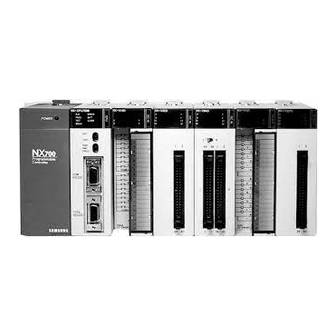
- Page 1 NX700 Series Controller NX-CPU700p User Manual...
- Page 2 Important User Information Solid state equipment has operational characteristics differing from those of electromechanical equipment. Because of these differences, and also because of the wide variety of uses for solid state equipment, all persons responsible for applying this equipment must satisfy themselves that each intended application of this equipment is acceptable.
-
Page 3: Table Of Contents
Contents 1. System Configuration ..........7 NX-CPU700p PLC Features and System Configuration....... 7 Module Types and Combinations ............... 10 Programming Tools..................14 2. Hardware Features and Specifications ..... 15 Overall Specifications................... 15 Backplane and Expansion Cable..............17 Processor Module ..................19 Power Supply Module .................. - Page 4 6. Programming Instructions ........87 Basic Sequence Instructions ................ 87 Timer, Counter and Shift Register Instructions.......... 88 Comparison Instructions ................89 Substitution, Increment and Decrement Instructions........ 89 Arithmetic Instructions ................. 90 Logical Instructions..................91 Rotation Instructions ..................91 Word Conversion Instructions ..............92 Bit Conversion Instructions................
- Page 5 Safety Instructions Please read this manual and the related documentation thoroughly and familiarize yourself with product information, safety instructions and other directions before installing, operating, performing inspection and preventive maintenance. Make sure to follow the directions correctly to ensure normal operation of the product and your safety.
- Page 6 Electrostatic Discharges ATTENTION Under dry condition, excessive electrostatic discharges may occur. Make sure to remove electrostatic discharges by touching a grounded metal piece before touching your controller system modules. Cleaning ATTENTION Never use chemicals such as thinner because they melt, deform or discolor PCB boards.
-
Page 7: System Configuration
System Configuration NX-CPU700p PLC Features and System Configuration System configuration NX-CPU 700p NX-X64D NX-X64D NX-X32D NX-Y32T NX-Y16RV NX-Y16RV NX-Y16RV NX-Y16RV POWER INIT TEST 40 39 1 PROG Programmable Controller RS232C OPEN TOOL RS232C 1 39 40 1 39 40 Communication cable (NX-CBLCPU02) WinGPC MMI S/W,... - Page 8 • High-capacity programming and memory backup The NX-CPU700p allows you to program up to 20K words. Built-in flash EEPROM allows you to save programs separately. • Self-diagnostics Self-diagnostics allows you to minimize system errors and maximize diagnostic efficiency. • Maximum 1600 I/O points With a 12-slot base backplane and a 12-slot expansion backplane, you can use up to 1600 I/O points (when all I/Os are configured with 64-point digital I/O modules).
- Page 9 I/O Backplanes and I/O Points 3-Slot Type 5-Slot Type NX-BASE03 NX-BASE0) 48 Points: 16-point I/O 80 Points: 16-point I/O 192 Points: 32-point I/O 320 Points: 64-point I/O 8-Slot Type 10-Slot Type NX-BASE08 NX-BASE10 128 Points: 16-point I/O 160 Points: 16-point I/O 512 Points: 64-point I/O 640 Points: 64-point I/O 12-Slot Type...
-
Page 10: Module Types And Combinations
Module Types and Combinations Combinations of backplanes and modules Backplanea 3-slot type: NX-BASE03 Processor module (common for base and expansion backplanes) NX-CPU700p COM1 PROG COM2 TEST ERROR BATT INIT TEST PROG COM 1 RS232C RS485 5-slot type: NX-BASE05 (common for base and NX-CPU700p COM 1 expansion backplanes) - Page 11 *: Available with NX-CPU700p v2.0 or higher I/O modules • 16-point • 16-point • 32-point • 64-point NX-X32D NX-X64D NX-X16D input output input input 24V dc In: Relay Out: 24V dc In: 24V dc In: ¥ ¥– 39 40 NX-X16D NX-Y16R NX-X32D NX-X64D...
- Page 12 Processor Module Specialty Module (1) Specialty Module (2) Specialty Module (2) I/O Module NX-CPU700p A/D, D/A, RTD, TC High-performance, 16-point type high-speed counter (4CH) 20k step, 0.2 µs CCU, SCU 32-point type 2 comm. ports Positioning module High-speed counter 64-point type WinGPC S/W (1, 2, 3, 4 axes) (1, 2CH)
- Page 13 Available Combinations and Restrictions Restrictions by Module ○ : Available, △ : Version 2.0 or higher required, : Not available Basic module Specialty module Network module Module Configuration Mount the modules in the following order, starting from the leftmost slot of the backplane.
-
Page 14: Programming Tools
Programming Tools Tools required for programming The following tools are required when programming with WinGPC. WinGPC software (for Windows) NX-CPU 700p NX-X64D NX-X64D NX-X32D NX-Y32T NX-Y16RV NX-Y16RV NX-Y16RV NX-Y16RV POWER INIT TEST 40 39 1 PROG Programmable Controller RS232C OPEN TOOL RS232C 1 39 40... -
Page 15: Hardware Features And Specifications
Hardware Features and Specifications Overall Specifications General specifications Item Specifications 0 °C to +55 °C (32 °F to 131 °F) Operating Temperature -25 °C to +70 °C (-13 °F to 158 °F) Storage Operating 30 to 85% RH (non-condensing) Humidity Storage 30 to 85% RH (non-condensing) 1500V ac for 1 minute between external terminal (ac) and frame ground (FG) - Page 16 Performance specifications Processor NX-CPU700p Control method Stored program, cyclic operation External I/O 1,600 points Basic 28 types Instructions Advanced 150 types Basic instructions 0.2 to 0.4 µs per step Processing speed Advanced 0.4 to several tens of µs per step instructions Max.
-
Page 17: Backplane And Expansion Cable
Backplane and Expansion Cable Backplane (NX-BASE03, NX-BASE05, NX-BASE08, NX-BASE10, NX-BASE12) Description 1. Backplane mounting hole This hole is for mounting a backplane on a control panel (control box). Use M5 screw for mounting. 2. Module mounting guide holes When mounting a module on the backplane, align the mounting clamp of the module with this hole. - Page 18 Backplane types Type Number of slots Catalog number Weight (g) Remarks NX-BASE03 250g Common for NX-BASE05 330g base and NX-BASE08 460g expansion NX-BASE10 570g backplanes NX-BASE12 660g Expansion cable (NX-EXPCBL) Expansion cable Cable length Catalog number Remarks 1.5m NX-EXPCBL15 Common for NX700 PLCs 0.8m NX-EXPCBL08...
-
Page 19: Processor Module
Processor Module NX-CPU700p processor module NX-CPU700p COM 1 P ROG COM 2 TE S T E RRO R B AT T INIT TEST PROG COM1 RS232C RS485 COM1 RS232C RS485 (Front) (Bottom) (Side) • Hardware features 1. Status LED Indicates the operation status of PLC, such as run, stop, error, and alarm. 2. - Page 20 • Status LEDs Color Description Green On when the processor is running. PROG Green On when the program can be edited. BATT On when the battery is not mounted or is low. TEST Green Not used COM1 Green Flashing when the processor is communicating via COM1. COM2 Green Flashing when the processor is communicating via COM2.
- Page 21 • Operating condition setting switches • Switch for termination resistance setting (DIP switch 1) Pin No. Description DIP Switch 1 setting For RS-485 communication, set both pins 3 and 4 to On if the system is a termination station. (Enables termination for COM1 terminal) For RS-485 communication, set both pins 3 and 4 to Off if the system is not a termination station.
-
Page 22: Power Supply Module
Power Supply Module POWER POWER FUSE FUSE USE ONLY USE ONLY 250V 1.5A 250V 1.5A 85-264 24V DC FRAME FRAME GROUND GROUND 24VDC 0.5A OUTPUT NX-POWER NX-PWRDC • Hardware features 1. Power status LED Turns on when power is on. 2. - Page 23 • Specifications Input type AC input power DC input power Catalog number NX-POWER NX-PWR220 NX-PWRDC 110 to 220V AC Input rated voltage 220V AC 24V DC Free Voltage ± Allowed voltage range 85 to 264V AC 176 to 264V AC 24V DC Input power frequency 47 to 63Hz...
-
Page 24: I/O Modules
I/O Modules NX-Y32T NX-X16D NX-Y64T ¥– ¥ 40 39 16-point type 32-point type 64-point type (A Type) (C Type) (B Type) • Hardware features 1. I/O Status LED Shows I/O ON/OFF status. 2. Terminal block fixing screw Fixes detachable terminal block on the unit. 3. - Page 25 Input unit specifications Product name DC input module Catalog number NX-X16D Number of input points 16 points Insulation method Photocoupler Rated input voltage 12 to 24V Operating voltage range 10.2 to 26.4V Max. input current 10mA or less (for 24V) ON voltage/current Min.
- Page 26 Product name DC input module Catalog number NX-X32D Number of input points 32 points Insulation method Photocoupler Rated input voltage 12 to 24V Use voltage range 10.2 to 26.4V Max. input current 10mA or less (for 24V) ON voltage/current Min. 9.6V OFF voltage/current Max.
- Page 27 Product name DC input module Catalog number NX-X64D Number of input points 64 points Insulation method Photocoupler Rated input voltage 12 to 24V Operating voltage range 10.2 to 26.4V Max. input current 10mA or less (for 24V) ON voltage/current Min. 9.6V OFF voltage/current Max.
- Page 28 Product name AC input module Catalog number NX-X16A110 NX-X16A220 Number of input points 16 points Insulation method Photocoupler Rated input voltage AC 100 to 120V AC 200 to 240V Operating voltage range AC 85 to 132V AC 170 to 264V Max.
- Page 29 Output module specifications Product name RELAY output module Catalog number NX-Y16R NX-Y16RV Number of output points 16 points Insulation method Photocoupler Rated load voltage 2A 250V AC, 2A 30V DC OFF → ON 10ms or less Response time ON → OFF 10ms or less Mechanical 30 million times...
- Page 30 Product name RELAY output module Catalog number NX-Y32RV Number of output points 32 points Insulation method Photocoupler Rated load voltage 1A 250V AC, 1A 30V DC OFF → ON 10ms or less Response ON → OFF time 10ms or less Mechanical 30 million times Life time...
- Page 31 Product name TR output module Catalog number NX-Y16T Number of input points 16 points Insulation method Photocoupler Rated load voltage 12 to 24V DC Operating load voltage range 10 to 30V DC Max. load current 0.6A/point OFF state leakage current 100 µA or less OFF →...
- Page 32 Product name TR output module Catalog number NX-Y32T Number of input points 32 points Insulation method Photocoupler Rated load voltage 12 to 24V DC Operating load voltage range 10 to 30V AC Max. load current 0.4A/point OFF state leakage current 100 µA or less OFF →...
- Page 33 Product name TR output module Catalog number NX-Y64T Number of input points 64 points Insulation method Photocoupler Rated load voltage 12 to 24V DC Operating load voltage range 10 to 30V AC Max. load current 0.2A/point OFF state leakage current 100 µA or less OFF →...
- Page 34 Product name SSR output module Catalog number NX-Y16SSR Number of input points 16 points Insulation method Rated load voltage 100 to 240V AC Operating load voltage range 85 to 264V AC Max. load current 0.5A/point OFF state leakage current 100 µA or less OFF →...
-
Page 35: Addressing Overview
Addressing Overview Addressing Overview All the memory used for external I/O processing and internal data processing has always both address and data (the content). Addressing space is classified as R, L, M, K, F , TC, and W. These letters are used to designate a specific area in memory as shown in the following table. -
Page 36: Bit And Word Addressing
The R, L, M, K, F , and TC areas can be used for both bit and word addressing. The W area can be used to process word data only. The L area can be used as internal contacts. Keep contact (K), data register (W), and counter's preset value register retain their last values before power was removed. -
Page 37: Double Word Addressing
Double Word Addressing Double word addressing is same with word addressing, except that 32-bit data is referenced by the specified address and its next address. The type of instruction used determines which addressing, word or double word addressing, is applied. For comparison instructions, the programmer must be in “Double Mode”... -
Page 38: Absolute Addressing
Absolute Addressing In LDR, DLDR, STO, and DSTO instructions, an absolute address is used to indirectly reference a register or to utilize the built-in communication port Absolute Absolute Register Register address address Classification Classification address address Dec. Hex. Dec. Hex. $0000 $01C0 $0001... -
Page 39: I/O Addressing
I/O Addressing Addressing is based on the location of the module. Example 1: 8-slot system Slot No. N X- C PU700p N X- X64D N X- X64D N X- X32D N X- Y32T N X- Y16R V N X- Y16R V N X- Y16R V N X- Y16R V POWER... - Page 40 Occupied I/O points by module (unit: word) The table below shows the occupied I/O points for each module when the memory space is allocated automatically by the system. I/O occupied Catalog number Input Output points NX-X16D NX-X16A110 NX-X16A220 NX-X32D NX-X64D NX-Y16R NX-Y16RV NX-Y16T...
-
Page 41: Special Registers
Special Registers Word registers F000 to F015 Address Function Description F000 register System check/control System self-check/program checking, operation control F001 register System check/clock 0.01/0.02/0.1 ms timer output, calculation results, carry flag F002 register Link control Link installation and operation mode setting F003 register Link control Link installation and operation mode setting... - Page 42 Word register F000 (F0.0 to F0.15) Only a bit process is available. Address Function Description Normal status When the power is applied, the system self-checks the F0.00 System check ROM. Should any fault exist, the error lamp is turned on. Output and operation are halted.
- Page 43 Word register F1 (F1.0 to F1.15) Only a bit process is available. Address Function Description Remarks Maintain On state for first single-scan period, when the CPU F1.0 First single scan shanges its status stop to Run. Cycle On/Off state for each scan during the program. F1.1 Scan clock (1Scan On, 1Scan Off)
- Page 44 Word register F12 (F12.0 to F12.15) Only a bit process is available. Address Function Description Remarks F12.0 RTC check On when the RTC is enabled. F12.2 Flash On when the 9.6 KW of flash memory is installed. F12.3 Flash On when the 16 KW of flash memory is installed. On when the battery is not connected or the voltage is F12.5 Battery error...
- Page 45 Special registers SR017 to SR511 (W2577 to W3071) May be changed - each is composed of 1 word. Address Function Description Gives result of self-diagnosis by CPU. Indicates error content . ← Watchdog time error = ON System error SR017 Undefined instruction = ON information Peripheral device fault = ON...
- Page 46 Program syntax error status register SR30 (W2590) Indicates the result of the automatic check on the user program syntax when the programmer or GPC executes a syntax check, and when the operation mode is switched from the Stop state to the Run state. If the value of W2590 is not zero, F004 bit turns On.
- Page 47 Real-time clock registers SR289 to SR297 (W2849 to W2857) Sets the time of the built-in clock (RTC) and stores and displays the present time. Data is stored in BCD format. ( ○ : bit = 0; × : bit change) Details Bit address Adjustment/...
-
Page 48: Timer/Counter Area
Timer/Counter Area Timer/counter set value and present value addresses Present Present Present Set value Channel value value Channel value value Channel value (SV) (SV) (PV) (SV) (PV) (PV) W2048 W2304 W2088 W2344 W2128 W2384 W2049 W2305 W2089 W2345 W2129 W2385 W2050 W2306 W2090... - Page 49 Present Present Set value Present Channel Channel value value Channel value value (SV) value (PV) (SV) (PV) (SV) (PV) W2260 W2516 W2168 W2424 W2214 W2470 W2261 W2517 W2169 W2425 W2215 W2471 W2262 W2518 W2170 W2426 W2216 W2472 W2263 W2519 W2171 W2427 W2217 W2473...
- Page 50 Address (register) Address refers to the location of memory being used. It can refer to the external I/O module and internal memory. An address is categorized into 1 bit, 16 bits (word), or 32 bits (double word). A bit is the minimum module required for calculation. It can be either On (1) or Off (0).
- Page 51 BCD (Binary Coded Decimal) BCD is used to express a decimal digit (0 to 9) using 4 bits. Conversion of BCD values can be done in hexadecimal calculations. Example: 59 (BCD) = 59 (HEX), 32 (BCD) = 32 (HEX) Flash ROM It refers to a ROM (EEPROM) that stores programs.
-
Page 52: Processor Operation Mode
• For bit operations, such as setting, resetting, shifting, or rotating Use the M, K, and R area. You cannot perform bit operations in the W area. • When you want to refer to or modify the set value of the timer or counter. -
Page 53: Processor Processing Procedure
Allowed Functions in Operation Modes =On, ◑ =Flashing, ● =Off LED status Initialize Operation mode Operation Program Data Mode at power switch is RUN LED selector switch mode change change off-on enabled PROG LED ● Disallowed Allowed ○ STOP ● Allowed Allowed ○... - Page 54 • Watchdog time initialization The watchdog elapsed time value is set to 0. (This value is the watchdog calculation point until the next scan.) The following illustration shows the difference between the relay board and PLC sequence processing. The relay carries out all sequences simultaneously while the PLC processes sequentially throughout the program.
-
Page 55: Installation And Wiring
Installation and Wiring Installation Installation space and environment dimensions (mm) External unit (mm) 3-slot type 5-slot type 8-slot type 10-slot type 12-slot type A (mm) 205.0 276.0 381.0 452.0 522.0 B (mm) 183.8 254.2 359.8 430.2 500.6... - Page 56 Installation location Be sure to maintain a sufficient distance from wiring ducts, and other machines below and above the module for proper ventilation. Do not install the modules stacked up or horizontally. Doing so will prevent proper cooling of the module and cause overheating inside the PLC (programmable controller).
-
Page 57: Power Supply Module Wiring
Avoid installing the module in the following conditions Ambient temperature outside the range of 0 to 55 °C • • Ambient humidity outside the range of 30 to 85% RH • Sudden temperature changes causing condensation • Inflammable or corrosive gases •... - Page 58 It is recommended that you use crimped terminal for wiring. Open type terminal Circular terminal 7.0mm 7.0mm or less or less Φ 3.7 to Φ 4.3 hole Use 2mm twisted pair cable or larger • Use power supply wire that is thicker than 2mm to minimize voltage drops.
- Page 59 Grounding Ground the PLC for noisy environments • Connected to the metal part of backplane, the frame ground terminal is connected to a solid earth ground. • Use ground wires with a minimum of 2mm and the triple grounding connection which has a resistance of less than 100 Ω.
-
Page 60: Input And Output Wiring
Input and Output Wiring Input wiring Checkpoints for input module wiring There can be limits on the number of points that can be simultaneously turned on, based on the module type. Check such limits in the specifications of each input module. In particular, be careful when using in high ambient temperature. - Page 61 Connection example with AC input device Contact output type AC input unit Input terminal terminal Non-contact output type AC input unit Input terminal terminal Cautions when using lead switch with LED Even when using input contact with embedded serial LED such as lead switch with LED, make sure to supply voltage higher than ON voltage to the PLC input terminal.
- Page 62 Cautions when using 2 wired type Use a breeder resistor as below when the leakage current from 2 wired type photoelectric switch or proximity switch keeps flowing into the PLC. DC 12-24V type input unit Ω (OFF voltage 2.5V, input impedance 3 2 wired sensor DC input unit Input...
- Page 63 Cautions when using limit switch with LED Use a breeder resistor as below when the leakage current from limit switch with LED keeps flowing into the PLC or LED is accidentally turned on. DC 12-24V type input unit (OFF voltage 2.5V, input impedance 3 KΩ) Limit switch with LED DC input unit Input...
- Page 64 Output wiring Checkpoints for output unit wiring There can be limits on the number of points that can be simultaneously turned on or load current, based on the unit type. Refer to the specification of each unit. Pay extra attention, in particular, when ambient temperature is high.
- Page 65 Cautions when using capacity load Use protection circuit as below to minimize the effect of a load with high inrush current. Output unit Resistor Output Load terminal terminal Output unit Inductance Output Load terminal terminal Use an external fuse to protect against overload Units embedded with fuse can prevent damages in case of output shortage.
-
Page 66: Terminal Block Type Module Wiring
Terminal Block Type Module Wiring Compressed terminal, M3.0 The terminal base for the NX70 PLC I/O modules (Terminal Type) uses M3.0 terminal screw. Use the following compressed terminals for terminal wiring. Open terminal Circular terminal 7.0mm 7.0mm or less or less Removable terminal block Terminal block of this type of I/O unit can be separated from the unit with wires connected, by unfastening the screws on both ends. -
Page 67: Connector Type Module Wiring
Connector Type Module Wiring Wiring Wiring method Both NX700 32-point I/O module (NX-X32D, NX-Y32RV, NX-Y32T) and 64-point I/O module (NX-X64D, NX-Y64T) use 40-pin MIL type connectors. To connect to external devices, 1. Insert each pin into socket 2. or, use harness with flat cables. (Available on the market) Connecting PIN type PIN type connection. - Page 68 Connecting with harness (Using flat cable connector) 40-pin flat cable connector is used, and 20 crimped terminals are connected at the end. Its total length is 1.5m. Direct connection to the unit. Product name Catalog number Product specifications DC IN 32 points, 64 points NX-CBLDC Connectors harness cable 1.5m TR OUT 32 points, 64 points...
- Page 69 Pressure welding socket for PIN type connection Direct pressure welding with clothings on saves wiring time and efforts. Wiring 1. Bend the contact part at a carrier, and set it into the pressure welding device. (Matsushita Electric Industrial Co.: AXY52000) 2.
- Page 70 Wiring flat cable connector Cautions when using flat cable connector When a flat cable connector is used for direct connection, the mapping between cable No. and I/O No. is as follows: Connecting 32-point unit (NX-X32D, NX-Y32T, NX-Y32RV) NX-X32D Product Catalog Specifications name number...
- Page 71 (NX-X64D, NX-Y64T) Connecting 64-point unit Catalog Product name Specifications number DC IN 64 points NX-CBLDC NX-X64D (NX-X64D) Flat cable (1.5m) TR OUT 64 points NX-CBLTR (NX-Y64T) Flat cable Flat cable Mapping table between flat cable No. and I/O (64 points) Symbols Symbols NX-X64D...
-
Page 72: Safety Measures
Safety Measures Precautions regarding system design In certain applications, malfunction may occur for the following reasons: • The timing difference between opening and closing of the PLC power supply, the I/O modules and power equipment • An operation time lag when a momentary power failure occurs •... -
Page 73: Nx-Cpu700P Processor Module Communications Specifications
NX-CPU700p Processor Module Communications Specifications Connection RS485 RS232C Remarks specification Transfer distance (Max) 1.2 Km 15 m Transmission speed 38,400, 19,200, 9,600, 4,800 bps DIP switch setting Protocol Half duplex asynchronous polling Parity No parity Stop bit 1 stop bit Cable type Twisted pair cable Use shield cable... -
Page 74: Eeprom Backup
EEPROM Backup What's EEPROM backup? EEPROM (Electric Erase Programmable Read Only Memory) can retain the data when the power is turned off, and erase or record data when the power is turned on. This function allows you to retain the PLC program when the power is turned off. -
Page 75: Test Run And Troubleshooting
Test Run and Troubleshooting Test Run Precautions Before installing the I/O wiring of the PLC and supplying power, check the following items. Item What to check • Check if the wiring is secured. • Check if the terminal screws are tightened. The connection of •... -
Page 76: Test Run Procedure
Test Run Procedure When the PLC has been installed and wired, begin test run in the following order. Item What to check/do • Check if the input voltage of the power supply module is within specifications. • Check if the power voltage for the I/O modules is within specifications. -
Page 77: Test Run Flow Charts
Test Run Flow Charts System check flow chart When you encounter problems during startup or test run, first of all, figure out the problems thoroughly. Check if the problems can be reproduced, and analyze the relevance to other devices. Then refer to the system check flow chart. - Page 78 Power check flow chart...
- Page 79 Run check flow chart...
- Page 80 Error check flow chart...
- Page 81 I/O check flow chart This page presents an example of a troubleshooting procedure based on the right circuit.
- Page 82 External environment check flow chart...
-
Page 83: Inspection And Maintenance
Inspection and Maintenance Inspection and maintenance Symptom Possible cause Action Power supply LED will not Fuse blows Replace the fuse illuminate. Replace the power supply or the Fuse blows frequently. Short circuit or defective part CPU module Program errors Correct the program Run LED will not illuminate. - Page 84 Output module Symptom Possible cause Action No external input power Supply power Low external input voltage Supply rated load power No outputs on an output module Loose terminal screw or defective Tighten the screw and reconnect will turn On. contact the module Defective I/O connector contacts Replace the output module...
- Page 85 Periodic inspection and maintenance items The NX-CPU700p controller requires periodic inspection and maintenance for proper operation. The following items should be checked every six months, but the period can be shortened according to the operational environment. Item Check item Requirement Remarks Does the voltage measured within the Voltage must be within the...
-
Page 87: Programming Instructions
Programming Instructions Refer to the NX7/NX70/NX700 Instruction Set Reference Manual for detailed IMPORTANT information on the NX7, NX70, and NX700 instruction set and for application examples to show the instruction set in use. Basic Sequence Instructions Mnemonic Name Ladder Symbol Description Start Starts contact A. -
Page 88: Timer, Counter And Shift Register Instructions
Timer, Counter and Shift Register Instructions Ladder Mnemonic Name Description Remarks Symbol Time base: Ch 0 to 63 = 0.01s Turns on after set delay Ch 64 to 255 = 0.1s time from input on Ch=00010 On Delay Timer Setting range: SV = 0 to 65535 Input SV=00050 Contact indicator: TC + channel... -
Page 89: Comparison Instructions
Comparison Instructions Word ladder Double word Mnemonic Name Description symbol ladder symbol STR == START == On if A is equal to B. AND == AND == A and B are word/double word or data value. OR == OR == On if A is not equal to B. -
Page 90: Arithmetic Instructions
Arithmetic Instructions Word ladder Double word Mnemonic Name Description symbol ladder symbol D = S1 + S2 Decimal addition (DADD) (Decimal operation) ADDB D = S1 + S2 BCD addition (DADDB) (BCD operation) D = S1 - S2 Decimal subtraction (DSUB) (Decimal operation) SUBB... -
Page 91: Logical Instructions
Logical Instructions Word ladder Double word Mnemonic Name Description symbol ladder symbol Store AND of S1 and S2 in D WAND AND (logical (DAND) multiply) Store OR of S1 and S2 in D OR (logical sum) (DOR) Store exclusive OR of S1 and S2 in D Exclusive OR WXOR (exclusive logical... -
Page 92: Word Conversion Instructions
Word Conversion Instructions Word ladder Double word Mnemonic Name Description symbol ladder symbol Convert binary value of S to BCD and store it in D. BCD Conversion S ..0 0 1 1 1 1 1 1 =63(DEC) (DBCD) D ..0 1 1 0 0 0 1 1 =$63 (BCD) Convert BCD of S to binary number and store it in D. -
Page 93: Bit Conversion Instructions
Bit Conversion Instructions Word ladder Double word Mnemonic Name Description symbol ladder symbol Set N bit of D to 1. BSET Bit Set When N=15 1 (N=0~15) Reset N bit of D to 0. BRST Bit Reset When N=3 Invert N bit of D. -
Page 94: Move Instructions
Move Instructions Word ladder Double word Mnemonic Name Description symbol ladder symbol Copy Ns words from Sr to D. Move When N=3 Repeatedly copy the value V to the Ns words starting from D. FMOV Fill Move When N=4 Move Ns bits from the bit address Sb to the bit address Db. -
Page 95: Program Control Instructions
Program Control Instructions Word ladder Double word Mnemonic Name Description symbol ladder symbol Execute instructions in the block For Loop between FOR and corresponding (DFOR) NEXT. Repeat execution D times. Decrement D of FOR instruction by 1. NEXT Next If it is not zero, repeat execution from FOR instruction. -
Page 96: System Control Instructions
System Control Instructions Word ladder Double word Mnemonic Name Description symbol ladder symbol Refresh external input (Receive input signal during program execution). INPR Input Refresh Ch is external input word address. Refresh external output (Send output signal during program OUTR Output Refresh execution). -
Page 97: Communications Control Instructions
Communications Control Instructions Word ladder Double word Mnemonic Name Description symbol ladder symbol Read Data READ Read NR3 words from the module (from shared memory address NR6 of the slot TO=RR1 READ memory of high SZ=NR3 NN5, and write them to the words performance FR=NN5:NR6 starting from RR1. -
Page 99: Nx-Cpu700P System Product Dimensions
NX-CPU700p System Product Dimensions System Dimensions unit (mm) unit (mm) 3-slot type 5-slot type 8-slot type 10-slot type 12-slot type A (mm) 205.0 276.0 381.0 452.0 522.0 B (mm) 183.8 254.2 359.8 430.2 500.6 Backplane Dimensions unit (mm) ¥ı 5 . 0 * 4 Slots 205.0 153.8... -
Page 100: Power Supply Module Dimensions)
Power Supply Module Dimensions) unit (mm) POWER Programmable 115. 5 Controller OPEN SAMSUNG 104. 0 43. 0 Processor and I/O Modules Dimensions unit (mm) NX- X16D NX- X64D N X- CPU 700p R U N E R R O R P R O G B AT T TE S T... -
Page 101: Specialty Module Dimensions
Specialty Module Dimensions unit (mm) NX- M W LI NK NX- SC U N X- ETHER N ET RESET LINK NO AU I 115. 5 COM1 RS232C RS485 COM2 RS232C RS485 F. G 35. 0 35. 0 35. 0 104. 0 NX-IOLINK Module Dimensions unit (mm) MODE SW... -
Page 102: Decimal, Bin, Hex, Bcd, Gray Code Cross-Reference Table
Decimal, Bin, Hex, BCD, Gray Code Cross-reference Table... -
Page 103: Ascii Code Table
ASCII Code Table SPACE “ & 〔 ‘ < ₩ 〕 > ∧... -
Page 105: Appendix. Communication Protocols
Appendix Communication Protocols The communication protocol of NX-CPU700p PLC provides a complete method of communications between the graphic consol programmers (WinGPC) and the PLC by controlling programs, CPU status, and I/O at user’s convenience. The user can easily expand the capabilities of the overall PLC system by communicating to the PLC using a variety of peripheral communications equipment in accordance with the following communication protocols and procedures. -
Page 106: Communication Protocols
Communication Protocols Step 1-Q Query Query Q (Query) is a signal sent from the peripheral devices to the PLC after setting the network ID number and the function code for the PLC to communicate with. Step 2-QA Query Acknowledge Query QA (Query Acknowledge) is a signal sent from the PLC to the peripheral devices, indicating that the Q signal from the peripheral device was received. - Page 107 When several CPU modules are connected to one communication network, they must use individual ID numbers. The PLC’s network ID number is configured using the WinGPC. Communication steps The NX CPU can support 2-step or 4-step communication methods. The communication methods are easily distinguished each other by selecting and sending the function code of the Q frame.
- Page 108 2-step communication method No communication error Peripheral device When R is not received 3 seconds Peripheral device Response to repeated function code Peripheral device 4-step communication method No communication error For the internal processing of the PLC CPU send RR at least 5 msec after receiving QA.
- Page 109 Function codes included in the query Each function code is 1 byte. When the PLC receives a query (Q), the function code of the final response (R) is formed by adding $80 (hex) to the function code sent by the query. The value added to the function code sent by the query differs for 2-step and 4-step by $20 (hex).
- Page 110 Cyclic Redundancy Checking (CRC) The CRC is a 2-byte checksum code attached to the end of the message by the sender to check if the communication frame is transmitted without error. The sender calculates the CRC when it sends one-byte message, and the receiver should also calculate the CRC from the data of the message.
-
Page 111: Structure Of Communication Frames
Structure of Communication Frames The function code is explained with the example of Query and Response frame based on the 2-step communication. Query (Q) and Response (R) frame Function code Length Information CRC L CRC H Length of information area CRC-16 code (byte) (2 bytes) - Page 112 Read bits Read the content of the bits (R, L, M, K, F , or TC) assigned to the absolute address. Can read n consecutive bits (On/Off). Query (Q) frame Number of bits to be read Length of information (byte) Absolute bit address (address of first bit to read) Function code...
- Page 113 Write bits Modify the contents of the bits stored in the absolute address (R, L, M, K, F , or TC). Change the bit state between On/Off. Can change multiple consecutive bytes. Query (Q) frame Base Base+0 Base+N+1 Base+N-3bit bit value bit value value To turn On the desired bit value from the base, enter $FF .
- Page 114 Write words Change the content of the words (R, L, M, K, F , or W) assigned to the absolute address. Can read n consecutive words. Query (Q) frame Base Base+0word Base+1word n word values from the base words requested by the Q. Length L = Nx2+2 Response (R) frame &00...
- Page 115 Write bits and words Read the bits and/or word contents of the assigned absolute addresses. Can read bits and words regardless of their order and location in memory. Query (Q) frame Method of assigning bit/word Assigning absolute addresses for bits absolute address Absolute address for the K127.12 bit = $1BFC...
-
Page 116: Communication Program Examples
Communication Program Examples Users can write a communication program by using the following example. For more information, contact the sales or technical department. Program Notes <PLC communication sample code> This program was written in Borland C++. It uses the peripheral devices such as PC to read M000 to M127 words, stores them in the K000 to K127, #include <stdio.h>... - Page 117 Program Notes * Initialization of GPC card */ GPC-300 card Setting (8255chip setting) Uses the communication card that is connected, and sets the environment if(port_number == 1) PORTADD=0x3F0; according to the PLC communication specifications, so that if(port_number == 2) PORTADD=0x2F0; communication is possible.
- Page 118 Notes Program void Job(void) Communication sequence function /* JobID=0 : Change to sending-mode for serial port */ JobID=0 to 4: handle Q and QA frames /* JobID=1 : Transmit sending-frame JobID=5 to 9: handle RA and R frames /* JobID=2 : Change to receiving-mode for serial port */ /* JobID=3 : Address polling of ACK from CPU */ /* JobID=4 : Receive ACK from CPU /* JobID=5 : Change to sending-mode for serial port */...
- Page 119 Notes Program break; JobID=4,9: case 4: Stores the received data in the internal receive buffer and compares the case 9:if(receiving_occuring()) CRC value sent by the PLC to the calculated CRC value. It notifies the system that a successful communication is made when the two values if(index<receiving_Index_max-1) match, and proceeds on to the next sequence.
- Page 120 Notes Program if(communication() == 0) printf("WRITE K0000-K0063 OK\n"); else printf("communication error\n"); receiving_frame[2]=4; /* EXAMPLE write WORD(K064-K0127) */ Writing function of the K Register receiving_frame[3]=130; /* Number Of Byte For Information */ Uses the communication function code 4 (writing N consecutive words) to receiving_frame[4]=0x80;...
- Page 122 NX700 Series Controller NX-CPU700p User Manual www.samsungautomation.co.kr Rockwell Samsung Automation Technical Support Export Sales Team 447-6, Gongse-Ri, Giheung-Eup, Youngin-City, Tel: 82-31-280-4768 Fax: 82-31-280-4900 Gyeonggi-Do, South Korea, 449-902 Tel: 82-31-280-4700 Fax: 82-31-280-4900 Trademarks not belonging to Rockwell Samsung Automation are property of their respective companies. Publication RSA-NX700-UM002B-EN-P - July 2005 Copyright ©...
Need help?
Do you have a question about the Samsung NX700 Series and is the answer not in the manual?
Questions and answers