Table of Contents
Advertisement
Micro830, Micro850, and Micro870
Programmable Controllers
Micro810 Controller Catalog Numbers 2080-LC10-12AWA, 2080-LC10-12QWB, 2080-LC10-12DWD, 2080-LC10-12QBB
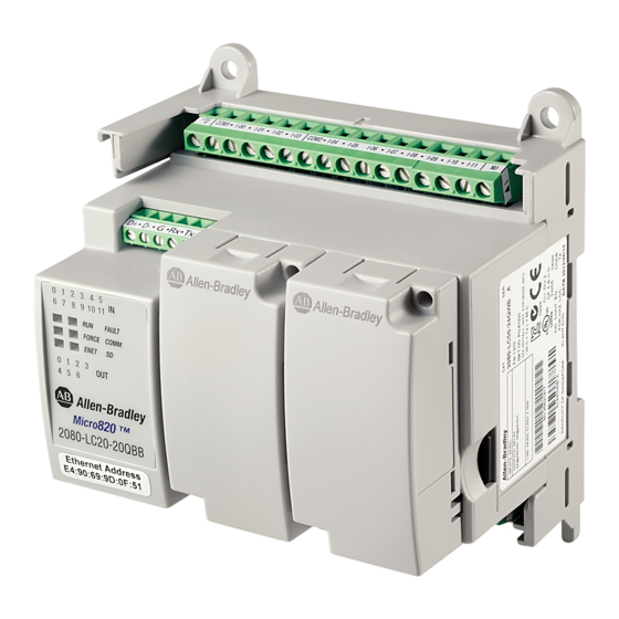
Micro820 Controller Catalog Numbers 2080-LC20-20AWB, 2080-LC20-20AWBR, 2080-LC20-20QWB, 2080-LC20-20QWBR,
2080-LC20-20QBB, 2080-LC20-20QBBR
Micro830 Controller Catalog Numbers 2080-LC30-10QWB, 2080-LC30-10QVB, 2080-LC30-16AWB, 2080-LC30-16QWB,
2080-LC30-16QVB, 2080-LC30-24QWB, 2080-LC30-24QVB, 2080-LC30-24QBB, 2080-LC30-48AWB, 2080-LC30-48QWB,
2080-LC30-48QVB, 2080-LC30-48QBB
Micro850 Controller Catalog Numbers 2080-LC50-24AWB, 2080-L50E-24AWB, 2080-LC50-24QWB, 2080-L50E-24QWB,
2080-LC50-24QVB, 2080-L50E-24QVB, 2080-LC50-24QBB, 2080-L50E-24QBB, 2080-LC50-48AWB, 2080-L50E-48AWB,
2080-LC50-48QWB, 2080-L50E-48QWB, 2080-LC50-48QWBK, 2080-L50E-48QWBK, 2080-LC50-48QVB, 2080-L50E-48QVB,
2080-LC50-48QBB, 2080-L50E-48QBB
Micro870 Controller Catalog Numbers 2080-LC70-24AWB, 2080-L70E-24AWB, 2080-LC70-24QWB, 2080-L70E-24QWB,
2080-LC70-24QWBK, 2080-L70E-24QWBK, 2080-L70E-24QWBN, 2080-LC70-24QBB, 2080-L70E-24QBB, 2080-LC70-24QBBK,
2080-L70E-24QBBK, 2080-L70E-24QBBN
User Manual
Original Instructions
Advertisement
Table of Contents
Troubleshooting


Need help?
Do you have a question about the Allen-Bradley Micro820 and is the answer not in the manual?
Questions and answers