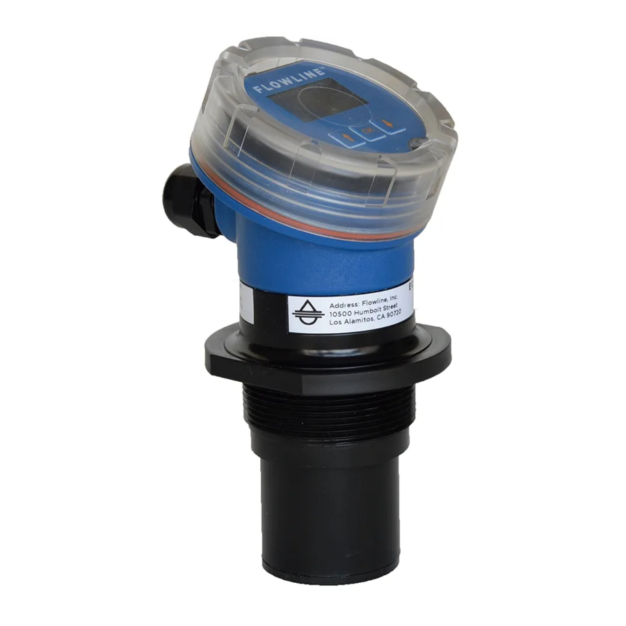
FlowLine EchoPod UG06 Series Quick Start Manual
Ultrasonic liquid level transmitter
Hide thumbs
Also See for EchoPod UG06 Series:
- Manual (52 pages) ,
- Quick start manual (12 pages) ,
- Manual (52 pages)
Table of Contents
Advertisement
Quick Links
See also:
Manual
Advertisement
Table of Contents

Related Manuals for FlowLine EchoPod UG06 Series


Summary of Contents for FlowLine EchoPod UG06 Series
- Page 1 ® EchoPod Ultrasonic Liquid Level Transmitter UG06 & UG12 Series Quick Start ©2017 Flowline, Inc. All Rights Reserved Made in USA Flowline, Inc. | 10500 Humbolt Street, Los Alamitos, CA 90720 p 562.598.3015 f 562.431.8507 w flowline.com QS310140 Rev A1...
- Page 2 Note: If using the Flowline LM90-1001 (liquid tight fitting) on the ½” conduit, the cable minimum is 0.170” (4.3mm) and the maximum is 0.450” (11.4mm).
- Page 3 , since it req quires conne ection to you ur PC. ® STEP P 1: INSTALL L WEBCAL SOFTWARE wnload WebC Cal® softwar re from w.flowline.co m/webcal-so oftware onto o a PC with t the following g minimum spec cifications: ® ® Wind...
-
Page 4: Step 4 - Sensor Configuration
STEP 4 - SENSOR CONFIGURATION Configures the Loop Fail-Safe, Output at Empty and Startup Condition for the sensor. STEP 5 – DIMENSIONAL ENTRY Distance Mode (default): Output of sensor is based on the distance (height of liquid) in the tank. Any change in liquid level will reflect linearly to the current output. -
Page 5: Step 6 - Tank Level Confirmation
STEP 6 - TANK LEVEL CONFIRMATION Verify the Height Units, Sensor Height & Fill-Height. All values were calculated and set in the previous Dimensional Entry window. Make any adjustments if required. QS310140 Rev A1... -
Page 6: Step 7 - Write To Unit
® * For complete information on the WebCal software, please refer to the WebCal manual located at flowline.com/webcal-software. Before configuration can be completed: You must click the Write to Unit button to save the settings to the unit. ... -
Page 7: Top-Level Menu
® NFIGURING E ECHOPOD DISPLAY) -LEVEL MEN sensor is co onfigured wit th the three buttons on t the sensor fa ace (UP, DO OWN and OK K) and the se ensor’s D. To access the sensor’ s Top-level menu, simpl ly hold down n the OK but tton for five s... -
Page 8: Troubleshoot
#3 - S SETTING TH HE HEIGHT (S SENSOR HEI IGHT) & #4 - SETTING TH HE FILL-H (F ILL-HEIGHT) This setting cust tomizes the reading for y your installa tion. Follo ow these ins structions to set the heig ht and fill he eight for your r tank:... - Page 9 Diameter). LM52-2890 Installation in open tanks and sumps: Use Flowline's LM50-1001 side mount bracket. Note: The Side Mount Bracket (LM50 series) is not designed for use with stand pipes or as a method to secure stand pipes. There are too few threads to properly hold the sensor and the stand pipe.
- Page 10 IMPORTANT MOUNTING GUIDELINES 1) Never mount the sensor at an angle. 2) Liquid should never enter the dead band. 3) Mount at least 3” from the side wall. 4) Never mount the sensor in a vacuum. 5) Do not obstruct the sensor’s beam width with objects underneath the sensor. 6) Avoid mounting in the center of a dome top tank.
- Page 11 ® WIRING THE ECHOPOD ® The following wiring diagram can be used for the 4-20 mA output of the EchoPod Notes on Safety Where personal safety or significant property damage can occur due to a spill, the installation must have a redundant backup safety system installed.
-
Page 12: Warranty
PERSON IS AUTHORIZED TO MAKE ANY OTHER WARRANTIES OR REPRESENTATIONS ON BEHALF OF FLOWLINE. This warranty will be interpreted pursuant to the laws of the State of California. If any portion of this warranty is held to be invalid or unenforceable for any reason, such finding will not invalidate any other provision of this warranty.
Need help?
Do you have a question about the EchoPod UG06 Series and is the answer not in the manual?
Questions and answers