Table of Contents
Advertisement
Quick Links
Advertisement
Table of Contents

Related Manuals for FlowLine EchoSonic II


Summary of Contents for FlowLine EchoSonic II
- Page 1 EchoSonic II Manual LU23-0, LU27-0, LU28-0, LU29-0, LU23-1, LU27-1, LU28-1, LU29-1 Series Flowline Inc. 10500 Humbolt Street Los Alamitos, CA 90720 Tel: (562) 598-3015 Fax: (562) 431-8507 www.flowline.com 23 MAR 11 EchoSonic II 1 of 24 Rev B MN300610...
- Page 2 On-line Warranty Registration can be found under Contact Us in the Navigation Bar along the side of the home page. If for some reason your product must be returned for factory service, go to the Flowline website to receive a Material Return Authorization number (MRA), providing the following information: 1.
- Page 3 Warranty Flowline warrants to the original purchaser of its products that such products will be free from defects in material and workmanship under normal use and service in accordance with instructions furnished by Flowline for a period, which is equal to the shorter of one year from the date of purchase of such products or two years from the date of manufacture of such products.
-
Page 4: Table Of Contents
Introduction: The EchoSonic II is a general-purpose ultrasonic level transmitter that provides a loop powered 4-20 mA output. The 4-20 mA output can be used to provide the proportional level of liquid in any tank or vessel. The signal can be connected to any device that accepts a loop powered 4-20 mA signal, such as a PLC, SCADA, DCS, display, controller, etc. -
Page 5: About This Manual
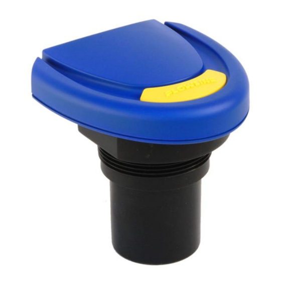
Always check for leaks prior to system start-up. Wiring and Electrical: A supply voltage of 12 to 28 VDC is used to power the EchoSonic II. Electrical wiring of the transmitter should be performed in accordance with all applicable national, state, and local codes. - Page 6 Warning: Always use the Viton gasket when installing the EchoSonic II, and make sure that all electrical wiring of the switch is in accordance with applicable codes. Components: EchoSonic II is offered in three different models. Depending on the model purchased, you may or may not have been shipped all the components shown below.
-
Page 7: Specifications
4 mA, 20 mA, 21 mA, Classification: General purpose 22 mA or hold last Compliance: CE, RoHS Approvals: cFMu Dimensions: Side View / LU27 Series Side View / LU23, LU28 and LU29 Series 23 MAR 11 EchoSonic II 7 of 24 Rev B MN300610... -
Page 8: Getting Started
Getting Started: EchoSonic II is configured through WebCal, a PC software program. WebCal is a free download from Flowline’s website. You must download and install WebCal prior to plugging in the USB® Fob. Please go to http://www.flowline.com, click on WebCal Software and select your language version. -
Page 9: Usb® Fob Interface
Fob into your computer’s USB® port, be sure that you have installed WebCal on your computer. Connect the red, green, white and black wires from EchoSonic II into the correct terminals on the Fob. Tighten the screws on the terminals and plug your Fob into the USB® port of your computer. -
Page 10: Step 1: Configuration
Note: Right click on any menu that you may have questions on to open the help menu. Note: To reset, press the Clear Screen button. 10 of 24 EchoSonic II 31 MAR 11 MN300610 Rev B... - Page 11 Typical installations are set with 4 mA at Bottom. This will not affect the performance of the sensor other than the output of the EchoSonic II. WebCal’s factory default is 4mA at bottom and 20mA at top. When connecting your sensor to a display, you must account for your output settings.
-
Page 12: Step 2: Tank Levels
EchoSonic. Now use WebCal’s file management features to save your configuration by clicking “Save Config File” and print your wiring diagram by clicking “Wiring Diagram.” Write to Unit Wiring diagram Save Config File 12 of 24 EchoSonic II 31 MAR 11 MN300610 Rev B... -
Page 13: Wiring
Wiring Diagram Wiring EchoSonic II After you have finished positioning and mounting EchoSonic II, follow WebCal’s wiring diagram to wire EchoSonic II. Flowline recommends using a qualified licensed electrician to wire EchoSonic II and your application’s components. Wire Connections: Red & Black Red and Black leads are for connection to a 24 VDC power supply or to a 4-20 mA loop power source. -
Page 14: Wiring To Displays, Controllers & Plc's
Voltage Output EchoSonic II can be used as a 0 to 5 or 0 to 10 VDC output device. A resistor will need to be added to the circuit to enable a voltage output (refer to the wiring diagram below). - Page 15 Wiring to Display, Controllers & PLC’s (continued) DataPoint LC52 Series DataPoint LC52 Series Level Controller Level Controller JWA mode (Factory Setting) JWB mode Generic Loop Generic PLC Powered Display 23 MAR 11 EchoSonic II 15 of 24 Rev B MN300610...
-
Page 16: Installation
Installation The EchoSonic II should always be mounted perpendicular to the liquid surface and installed using the provided Viton mounting gasket. Make sure that the fitting and transmitter threads are not damaged or worn. Always hand-tighten the transmitter within the fitting. Perform an installed leak test under normal process conditions prior to system start up. -
Page 17: Fitting Selection
Installation in existing fittings If the existing fitting is larger than the threads of the EchoSonic II, select a reducer bushing such as the LM52-1400 (2” thread x 1” thread) or LM52-2400 (3” thread x 2” thread). Metal Tanks (LU27 series) Flowline ultrasonic transmitters have been optimized for use in non-metallic fittings. -
Page 18: Flange
For the LU27 series, order the LM50-1001-1, which includes a 2”x 1” Reducer Bushing. b. For the LU23, LU28 & LU29, series, order the LM50-1001 side mount bracket. 18 of 24 EchoSonic II 31 MAR 11 MN300610 Rev B... -
Page 19: Stand Pipe
A 2” pipe is usable with the LU27 series, but is the minimum. ii. Pipes larger than 3” can also be used. c. Use a coupling and reducer bushing to attach the EchoSonic II to the pipe. i. With the LU27 series, be sure to use a plastic reducing bushing such as LM52-1400 2”... -
Page 20: Advanced Feature
Please read through this HELP file to assist you in making adjustments or if still unclear about a specific issue, please contact FLOWLINE, Applications Engineering. NOTE: When the Advanced Button is highlighted with a RED border, this indicates you have selected an advanced feature…... -
Page 21: Appendix
When the Download button is pressed, the software will check the version of software you re using with the most recent version at Flowline. If the versions are similar, a window indicating that the most recent version is installed. If not, then a window will appears asking to download the latest version. Follow the instructions for installing the latest version. -
Page 22: Updating Transmitter Firmware
Updating Transmitter Firmware WebCal software can also be used to update the firmware inside the EchoSonic II transmitter. This feature allows the transmitter to be updated when new features are added. First open WebCal with an EchoSonic II transmitter connected and the latest version of WebCal downloaded to your PC. -
Page 23: Factory Defaults
2. Verify that the current increases (tank filling) and decreases (tank emptying) appropriately in the calibrated span. 3. If not, carefully observe and attempt to correlate any installation, level or application event for more specific troubleshooting direction. 23 MAR 11 EchoSonic II 23 of 24 Rev B MN300610... -
Page 24: Troubleshooting
Transmitter indicates a Immediately check the wiring for a short circuit. The EchoSonic II is current current over 23 mA limited to 22 mA. Anything above 23 mA indicates a short circuit.
Need help?
Do you have a question about the EchoSonic II and is the answer not in the manual?
Questions and answers