Table of Contents
Advertisement
Quick Links
Download this manual
See also:
Manual
Advertisement
Table of Contents

Related Manuals for FlowLine EchoPod DL34 Series


Summary of Contents for FlowLine EchoPod DL34 Series
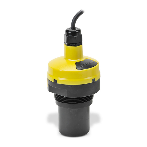
- Page 1 Ultrasonic Liquid Level Switch, Controller & Transmitter DL34 Series Quick Start DL34-00 Shown ©2019 Flowline, Inc. All Rights Reserved Made in USA Flowline, Inc. | 10500 Humbolt Street, Los Alamitos, CA 90720 p 562.598.3015 f 562.431.8507 w flowline.com QS204215 Rev B...
- Page 2 If you have a non-standard installation or setup requirement that is not addressed ® here, please refer to the EchoPod Manual or other support documentation located at flowline.com. WE DO YOUR LEVEL BEST ® Thank you for purchasing EchoPod .
-
Page 3: Step 2: Connect The Usb
, a PC software program. Configuration of your sensor should be performed prior to mounting, since it requires connection to your PC. ® STEP 1: DOWNLOAD AND INSTALL WEBCAL Download WebCal® software from www.flowline.com/webcal-software onto a PC with the following minimum specifications: ® ®... -
Page 4: Output Configuration
WebCal . If you need additional assistance using WebCal , please ® contact a Flowline applications engineer at (562) 598-3015. *For complete information on the WebCal ® software, please refer to the WebCal manual located at flowline.com/webcal-software. -
Page 5: Tank Shape Selection
TANK SHAPE SELECTION Defines the shape of the tank as well as the dimensional information for the tank with respect to the sensor’s location on the tank. TANK LEVEL CONFIGURATION Enters the settings for the relay activation points as well as confirms the operational range. QS204215 Rev B... -
Page 6: Write To Unit
® * For complete information on the WebCal software, please refer to the WebCal manual located at flowline.com/webcal-software. Before configuration can be completed: You must click the Write to Unit button to save the settings to the unit. ... - Page 7 Changing these setting will alter the factory default performance or operation, of your sensor. Please read through this HELP file to assist you in making adjustments or if you are still unclear about a specific issue, please contact FLOWLINE applications engineering. The more commonly used Advanced features are the Invert Relay and Increase Output Filtering described below.
- Page 8 Make sure that there are no restrictions or obstacles in the path of the acoustic signal. For further ® mounting information, please refer to the EchoPod manual and instruction video located at flowline.com. Mounting with a Tank Adapter Select a tank adapter fitting, such as the LM52-2890.
- Page 9 IMPORTANT MOUNTING GUIDELINES 1. Never mount the sensor at an angle. 2. Liquid should never enter the dead band. 3. Mount sensor at least 3” from the side wall. 4. Never mount the sensor in a vacuum. 5. Do not obstruct the sensor’s beam width. MOUNTING IN STAND-PIPE A stand-pipe may be used to dampen turbulence, separate surface foam from the point of measurement or increase performance in heavy vapor.
-
Page 10: Wiring Echopod
® WIRING ECHOPOD After mounting the sensor, make the necessary electrical connections. A wiring diagram with specific ® recommendations for the sensor’s configuration can be printed from the WebCal program. A typical wiring diagram is shown on the next page. Red &... -
Page 11: General Notes For Electrical Connections, Usage And Safety
® WIRING ECHOPOD Sample Wiring Diagram Diagram will change based upon the sensor’s configuration, use ® WebCal to view appropriate wiring diagram. Typical wiring diagram (DS14) shown. Diagrams will change based upon your exact sensor series and configuration. Print and use the appropriate ® wiring diagram in WebCal GENERAL NOTES FOR ELECTRICAL CONNECTIONS, USAGE AND SAFETY: ... -
Page 12: Warranty
PERSON IS AUTHORIZED TO MAKE ANY OTHER WARRANTIES OR REPRESENTATIONS ON BEHALF OF FLOWLINE. This warranty will be interpreted pursuant to the laws of the State of California. If any portion of this warranty is held to be invalid or unenforceable for any reason, such finding will not invalidate any other provision of this warranty.
Need help?
Do you have a question about the EchoPod DL34 Series and is the answer not in the manual?
Questions and answers