Sign In
Upload
Manuals
Brands
IEI Technology Manuals
Monitor
LCD-KIT-F12A LCD
IEI Technology LCD-KIT-F12A LCD Manuals
Manuals and User Guides for IEI Technology LCD-KIT-F12A LCD. We have
1
IEI Technology LCD-KIT-F12A LCD manual available for free PDF download: User Manual
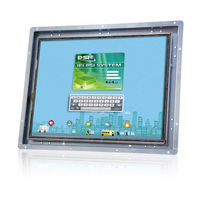
IEI Technology LCD-KIT-F12A LCD User Manual (99 pages)
12.1" - 19" Open Frame LCD Monitor VGA, DVI-D, RoHS
Brand:
IEI Technology
| Category:
Monitor
| Size: 3.48 MB
Table of Contents
Table of Contents
5
1 Introduction
12
Features
13
Figure 1 1: LCD-KIT-F Series
13
Table 1-1: LCD-KIT-F Series Model Variations
14
Figure 1-2: Typical LCD-KIT-F Front View
15
Connectors
16
Applications
15
External Overview
15
Front View
15
Rear View
15
Lcd-Kit-F Series Lcd Monitor Overview
13
Model Variations
14
Figure 1-3: Typical LCD-KIT-F Rear View
16
Figure 1-4: Typical LCD-KIT Connectors
17
Series Specifications
17
Certifications
18
2 Mechanical Overview
19
Connector Panel
20
Figure 2-1: Rear Panel
20
Introduction
20
Rear Panel
20
Available Connectors
21
Physical Dimensions
21
General Physical Dimensions
21
Table 2-1: General Physical Dimensions
21
Figure 2-2: LCD-KIT-F-12A Physical Dimensions (Millimeters)
22
Figure 2-3: LCD-KIT-F-15A Physical Dimensions (Millimeters)
23
Figure 2-4: LCD-KIT-F-17A Physical Dimensions (Millimeters)
24
LCD-KIT-F-17A Physical Dimensions
24
Figure 2-5: LCD-KIT-F-19A Physical Dimensions (Millimeters)
25
LCD-KIT-F-19A Physical Dimensions
25
Mounting Holes
26
LCD-KIT-F-15A Physical Dimensions
23
LCD-KIT-F-12A Physical Dimensions
22
Table 2-2: Mounting Holes
26
3 Lcd Specifications
27
Lcd Specifications
28
LCD-KIT-F12A LCD Specifications
28
LCD-KIT-F15A LCD Specifications
28
Table 3-1: LCD-KIT-F12A LCD Specifications
28
Table 3-2: LCD-KIT-F15A LCD Specifications
29
LCD-KIT-F19A LCD Specifications
30
LCD-KIT-F17A LCD Specifications
29
Table 3-4: LCD-KIT-F19A LCD Specifications
30
Table 3-3: LCD-KIT-F17A LCD Specifications
30
DC Module
31
Power Adapters
31
Table 3-5: Power Adapter Specifications
31
Table 3-6: 9~36V DC Module Specifications
31
4 Ad Board
32
Ad Board Overview
33
Av-60381 Ad Board
33
AV-60381 Peripheral Interface Connectors
33
Figure 4-1: AV-60381 AD Board Layout Diagram
33
Table 4-1: AV-60381 Peripheral Interface Connectors
34
LVDS Connector (LVDS1)
35
OSD Keypad Connector (KEYPAD1)
35
Backlight Inverter Connector (INVERTER1)
34
Table 4-2: Backlight Inverter Connector (INVERTER1) Pinouts
35
Table 4-3: LVDS Connector (LVDS1) Pinouts
35
Table 4-4: OSD Keypad Connector (KEYPAD1) Pinouts
35
Table 4-7: USB Connector for Touchscreen (USB_TOUCH1) Pinouts
36
Table 4-6: RS-232 Connector for Touchscreen (RS232_1) Pinouts
36
Table 4-5: Power Input Connector (PWR2) Pinouts
36
Backlight Voltage Select Jumper (JP5)
37
LVDS Panel Voltage Select Jumper (JP2)
37
VGA Connector (VGA2)
37
Power Input Connector (PWR2)
36
RS-232 Connector for Touchscreen (RS232_1)
36
Touchscreen Connector (J1)
36
USB Connector for Touchscreen (USB_TOUCH1)
36
Table 4-11: LVDS Panel Voltage Select Jumper (JP2) Pinouts
37
Table 4-10: Backlight Voltage Select Jumper (JP5) Pinouts
37
Table 4-9: VGA Connector (VGA2) Pinouts
37
Table 4-8: Touchscreen Connector (J1) Pinouts
37
Power Input Setting Jumper (JP4)
38
Touchscreen Type Select Jumper (JP1)
38
Table 4-12: Power Input Setting Jumper (JP4) Pinouts
38
Table 4-13: Touchscreen Type Select Jumper (JP1) Pinouts
38
5 Installation
39
Installation Precautions
40
Unpacking
41
Packaging
41
Unpacking Procedure
41
Packing List
42
Connectors
43
VGA Connector
44
DVI-D Connector
44
Pre - Installation Preparation
43
Tools
43
Figure 5-1: VGA Connector
44
Table 5-1: Rear Panel Connectors
44
Table 5-2: VGA Connector Pinouts
44
Table 5-3: DVI-D Connector Pinouts
45
Figure 5-4: 3-Pin Terminal Block
46
Figure 5-5: RS-232 Touch Panel Connector
46
RS-232 for Touch Panel Connector
46
Table 5-4: RS-232 Touch Panel Connector Pinouts
46
Figure 5-6: USB Touch Panel Connector
47
Mounting the Lcd-Kit-F Series Lcd Monitor
47
Panel Mounting
47
Table 5-5: USB Touch Panel Connector Pinouts
47
USB for Touch Panel Connector
47
Figure 5-3: 12V Power Connector
45
Figure 5-2: DVI-D Connector
45
Power Connector
45
36 V Terminal Block (Optional)
45
Figure 5-7: Mounting Clamps Holder
48
Figure 5-8: Mounting Clamps
48
Figure 5-9: Secure the Mounting Clamps Holders
49
Figure 5-10: Panel Mounting Clamp Position
49
Figure 5-11: Mounting Clamps Holder Dimensions
50
Figure 5-12: Ultra Set Plate Dimensions
50
Figure 5-13: Bolt Dimensions
50
Figure 5-14: Steering Button Dimensions
51
6 On-Screen-Display (Osd) Controls
52
Figure 6-1: OSD Keypad
53
Osd Keypad
53
Table 6-1: OSD Control Buttons
53
Table 6-2: OSD Menu Structure
54
Figure 6-2: Image Menu
55
Color Setting
56
Figure 6-3: Color Settings
56
Display Menu
57
Figure 6-4: Display Menu
57
Figure 6-5: System Menu
58
System Menu
58
Figure 6-6: Input Options
59
Input
59
OSD Settings
60
Using the Osd
55
Image Menu
55
Osd Menu Structure
54
Figure 6-7: OSD Settings Menu
60
7 Software Driver
61
Introduction
62
Rs-232 or Usb Touch Screen
62
Figure 7-1: Setup Icon
63
Touch Panel Driver Installation
63
Figure 7-2: Welcome Screen
64
Figure 7-3: License Agreement
64
Figure 7-4: Initiate Install
65
Figure 7-5: Installation Starts
65
Calibrating the Touch Screen
66
Change the Touch Screen Interface
66
Figure 7-6: Finish Installation
66
Figure 7-7: Penmount Monitor Icon
67
Figure 7-8: Penmount Monitor Popup Menu
67
Figure 7-9: Configuration Screen
67
Figure 7-10: Calibration Initiation Screen
68
Figure 7-11: Calibration Screen
68
A Regulatory Compliance
69
B Safety Precautions
73
Safety Precautions
74
General Safety Precautions
74
Anti-Static Precautions
75
Product Disposal
76
Maintenance and Cleaning Precautions
77
Maintenance and Cleaning
77
Cleaning Tools
77
C Smartosd
79
Iei Smart Osd Quick Installation Guide
80
Pre - Installation Notice
80
Smart Osd Installation
80
Software Illustration
83
C.4 S Oftware I Llustration
83
Table C-1: Smartosd Menu Structure
85
Manage Page
86
EDID Page
87
Image Page
88
Display Page (for Analog Signal)
89
Color Page
90
PIP Page
91
System Page
92
About Page
93
Smart Osd Faq
94
Windows 2000 Installation Failure
94
Vista Installation Failure
94
C.5 Smart Osd Faq
94
Model Failure
95
DDC Port Failure
96
D Hazardous Materials Disclosure
97
Advertisement
Advertisement
Related Products
iEi Integration LCD-KIT-F12A/R-R10
iEi Integration LCD-KIT-F12A/TW-R10
iEi Integration LCD-KIT-F12A/PC-R10
IEI Technology LCD-KIT-F15A LCD
iEi Integration LCD-KIT-F15A/R-R10
iEi Integration LCD-KIT-F19A/R-R10
iEi Integration LCD-KIT-F15A/TW-R10
iEi Integration LCD-KIT-F17A/TW-R10
iEi Integration LCD-KIT-F15A/PC-R10
iEi Integration LCD-KIT-F19A/PC-R10
IEI Technology Categories
Motherboard
Touch Panel
Computer Hardware
Single board computers
Desktop
More IEI Technology Manuals
Login
Sign In
OR
Sign in with Facebook
Sign in with Google
Upload manual
Upload from disk
Upload from URL