
Related Manuals for Helios ALB Series


Summary of Contents for Helios ALB Series
- Page 1 Helios Ventilatoren MONTAGE- UND BETRIEBSVORSCHRIFT NR. 91832 Helios Außenluft-Boxen ALB.. ALB-220/4/50/30 WW/EH ALB-280/4/60/35 WW/EH...
-
Page 2: Table Of Contents
DEUTSCH Inhaltsverzeichnis KAPITEL 1. SICHERHEIT ..............Seite 1 1.0 Wichtige Informationen . -
Page 3: Wichtige Informationen
Montage- und Betriebsvorschrift Außenluft-Boxen Wichtige Informationen KAPITEL 1 Zur Sicherstellung einer einwandfreien Funktion und zur eigenen Sicherheit sind alle nachstehenden Vorschriften genau durchzulesen und zu beachten. Dieses Dokument ist Teil des Produktes und als solches zugänglich und dauerhaft auf- SICHERHEIT zubewahren. -
Page 4: Einsatzbereich
Montage- und Betriebsvorschrift Außenluft-Boxen • Gerätedeckel nicht öffnen, wenn das Gerät in Betrieb ist! • Gerät bis zum Einbau nur verpackt bewegen! • Gerät nur mit für das Gewicht geeigneten Transportmitteln bewegen, beim Transport Sicherheitsschuhe tragen! • Beim Auspacken des Geräts Handschuhe/Sicherheitsschuhe tragen. •... -
Page 5: Berührungsschutz
Montage- und Betriebsvorschrift Außenluft-Boxen Berührungsschutz Beim Einbau sind die allgemein gültigen Arbeitsschutz- und Unfallverhütungsvorschriften einzuhalten! Der Betreiber ist für die Einhaltung verantwortlich! – Kontakt mit rotierenden Teilen muss verhindert werden. – In Abhängigkeit der Einbauverhältnisse kann ein Berührungsschutz erforderlich sein. Entsprechende Schutzgitter sind vorzusehen. -
Page 6: Garantieansprüche - Haftungsausschluss
KAPITEL 2 Alle Ausführungen dieser Dokumentation müssen beachtet werden, sonst entfällt die Gewährleistung. Gleiches gilt für Haftungsansprüche an Helios. Der Gebrauch von Zubehörteilen, die nicht von Helios empfohlen oder angeboten ALLGEMEINE HINWEISE werden, ist nicht statthaft. Eventuell auftretende Schäden unterliegen nicht der Gewährleistung. Veränderungen und Umbauten am Gerät sind nicht zulässig und führen zum Verlust der Konformität, jegliche Gewährleistung und Haftung... -
Page 7: Zubehör
Montage- und Betriebsvorschrift Außenluft-Boxen Zubehör ALB 220/4/50/30 WW / Best. Nr. ALB 280/4/60/35 WW / Best. Nr. Ersatz- und Pollenfilter ELF-ALB 220/4/50/30 G4 / 3646 ELF-ALB 280/4/60/35 G4 / 3649 ELF-ALB 220/4/50/30 M5 / 3647 ELF-ALB 280/4/60/35 M5 / 3650 ELF-ALB 220/4/50/30 F7 / 3648 ELF-ALB 280/4/60/35 F7 / 3654 Hydraulikeinheit... - Page 8 Gerät einschalten Œ ‘ Touch-Screen antippen Œ Hauptmenü ’ Uhrzeit ± Ž Power-Off Zeitschaltuhr aktiv “ Warnsymbol/Fehleranzeige ‘ Nachtmodus aktiv Ž ’ Position/Temp. Steuersensor = anwählbares Element “ Ventilatorstufe (1-5 bzw. Auto.-Modus)
-
Page 9: Bedienoberfläche
Bedienoberfläche Einstellen der Sollwerttemperatur Einstellung der Sollwerttemperatur im Bereich von 5-30°C in 1°C Schritten. *Anzeige aktueller Fühler Œ Solltemperatur einstellen Fühler im Bedienteil Position/Temp. Fühler* ± Fühler Zuluft Œ Ž Bestätigung u. zurück Ž Fühler Abluft Einstellung Fühlerposition: Einstellen der Ventilatorstufe Konfigurationsmenü... - Page 10 Montage- und Betriebsvorschrift Außenluft-Boxen Zeitschaltuhr Œ Zeiten anzeigen Ž Bestätigung u. zurück ± Œ Ž Zeitschaltuhr ein/aus Tag-/Wochenmodus Zeitschaltuhr einstellen Hauptmenü > Zeitschaltuhr: Wochenmodus Für jeden Wochentag lassen sich vier individuelle Einschaltzeiten einstellen. Œ...
- Page 11 Montage- und Betriebsvorschrift Außenluft-Boxen > Konfigurationsmenü: Gerätemodus Œ Bestätigung u. zurück Ž Intervall f. Temperaturänderungen ± Ž Modus manuell/auto Funktion nicht aktiv (typenabhängig) Œ Offseteinstellung der Konfigurationsmenü Zu-/Abluftgeräte * Beispiel: Wird „ -2” gewählt, ist die Dreh- Œ...
- Page 12 Montage- und Betriebsvorschrift Außenluft-Boxen > Konfigurationsmenü: PID Konst. Einstellung der Regelungskurve, nur nach Rücksprache mit dem Hersteller zu tätigen (Kapitel 4.4). ± Konfigurationsmenü > Konfigurationsmenü: Temperaturfühler Die Soll-Temperatur wird am gewählten Fühler erreicht und gehalten. Œ Bestätigung u. zurück ...
- Page 13 Montage- und Betriebsvorschrift Außenluft-Boxen > Konfigurationsmenü: Reinigungseinstellungen Œ Bestätigung u. zurück Ž Filterreinigung in Abhängigkeit der ± Betriebsstunden Ž Filterreinigung in Abhängigkeit des Œ Druckverlustes Konfigurationsmenü Bei Filterreinigung in Abhängigkeit der Betriebsstunden wird nach 720 Betriebsstunden mit voller Ventilatorleistung die Aufforderung zur Filterreinigung (oder Filterwechsel) angezeigt.
-
Page 14: Parametereinstellungen
Montage- und Betriebsvorschrift Außenluft-Boxen Parametereinstellungen K*T zu gering K*T zu hoch I zu gering I zu hoch Optimale Einstellung K - Verstärkung T - Zeit I - Integraler Anteil... -
Page 15: Benutzerwartung
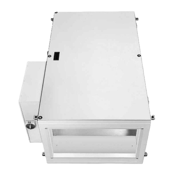
Montage- und Betriebsvorschrift Außenluft-Boxen Benutzerwartung KAPITEL 5 Es ist keine Benutzerwartung vorgesehen. BENUTZERWARTUNG Alle anfallenden Wartungsarbeiten sowie die Reinigung dürfen nur durch eine Elektrofachkraft erfolgen. ACHTUNG Alle nachfolgenden Informationen und Anweisungen sind nur für eine autorisierte Elektrofachkraft bestimmt! Konstruktiver Aufbau KAPITEL 6 Abb.1 Abluftstutzen... -
Page 16: Elektrischer Anschluss
Montage- und Betriebsvorschrift Außenluft-Boxen Abb.2 Montagepositionen (Blick auf Ausblasseite) REVISIONS- ÖFFNUNG (BEIDSEITIG) Abhängepunkte Abb.3 Type ALB 220/4/50/30.. 1045 ALB 280/4/60/35.. 1085 Elektrischer Anschluss Vor allen Wartungs- und Installationsarbeiten oder vor Öffnen des Anschlussraums ist das Gerät allpolig vom ACHTUNG Netz zu trennen und gegen unerwünschtes Wiedereinschalten zu sichern! –... -
Page 17: Anschluss Externer Komponenten
Montage- und Betriebsvorschrift Außenluft-Boxen Anschluss Schutzleiter (PE) über PE-Klemme (Abb. 5), Anschluss der Stromzufuhr über Hauptschalter (Abb. 4): 1 ~ 230V L1/N/ 3 ~ 400V L1/L2/L3/N/ (L1= Steuerphase) Leitung nie über scharfe Kanten führen! ACHTUNG Abb.4 Abb.5 Abb.6 Stromzufuhr L1, L2, L3 Drehrichtung des angeschlossenen Ventilators überprüfen! ACHTUNG Anschluss des Warmwasser-Heizregisters (Typen ..WW) - Page 18 Montage- und Betriebsvorschrift Außenluft-Boxen 6.4.2 Verbindung der Außenluftbox und Abluftsteuerung ALB-AS.. Wenn zusätzlich zum Hauptgerät ein Abluftgerät montiert wird, werden beide über ein gemeinsames Bedienteil gere- gelt, das am Hauptgerät montiert wird. Die Regelungen beider Einheiten werden mit einer Steuerleitung verbunden. - Steuerleitung an den Stecker der Platine des Abluftgerätes anschließen.
-
Page 19: Inbetriebnahme
Montage- und Betriebsvorschrift Außenluft-Boxen 6.4.4 Anschluss: Umwälzpumpe Siehe Anschlussplan SS 1121/1122, Punkt 17. 6.4.5 Anschluss: Mischeransteuerung Siehe Anschlussplan SS 1121/1122, Punkt 9. 6.4.6 Anschluss: Außenluftklappe ACHTUNG Die Montage einer Rohrverschlussklappe (RSK..) in die Außenluftleitung ist zwingend erforderlich. Bei ausgeschaltetem Gerät können so keine Frostschäden auftreten oder kalte Luft in das Gebäude gezogen werden! Siehe Anschlussplan SS-1121 bis SS-1124, Punkt 16. -
Page 20: Inbetriebnahme Alb Mit Elektroheizung
Montage- und Betriebsvorschrift Außenluft-Boxen Inbetriebnahme ALB mit Elektroheizung Durch Inbetriebnahme werden Ansaug- und Ausblasklappen geöffnet und der Ventilator wird eingeschaltet. Die Regelung wird vom elektronischen Temperaturregelsystem mit den integrierten Temperaturfühlern und dem Sollwertgeber übernommen. Die Regelung erfolgt stufenlos durch zeitproportionale Steuerung. Das Verhältnis zwischen Ein- und Ausschaltzeit wird an den vorhandenen Leistungsbedarf angepasst. -
Page 21: Reinigung
– Durchströmungsbereich, Laufrad, Verstrebung und Motor des Ventilators säubern. – Keine aggressiven, lacklösenden Mittel verwenden! – Hochdruckreiniger oder Strahlwasser sind nicht gestattet! Ersatzteile Es sind ausschließlich Helios Originalersatzteile zu verwenden. Alle Reparaturen dürfen nur von autorisiertem/en Fachpersonal/-Betrieben durchgeführt werden. Stilllegen und Entsorgen WARNUNG! WARNUNG Bei der Demontage werden spannungsführende Teile freigelegt, die bei Berührung zu einem elektrischen... -
Page 22: Fehlerbeschreibung
Montage- und Betriebsvorschrift Außenluft-Boxen Fehlerbeschreibung Fehlermeldungen im Startbildschirm Display Geräteverhalten Problem Lösung Das Gerät läuft Überhitzung des Heizregisters Kontrolle, ob die Luft im Gerät frei zirkulieren kann, das Heizregister wird nicht genügend gekühlt. ERROR 1 Das Gerät läuft nicht Frostschutz bei Warmwasser- Kontrolle, ob Temp. -
Page 23: Kapitel 8. Schaltpläne
Montage- und Betriebsvorschrift Außenluft-Boxen Anschlussplan SS-1121 KAPITEL 8 SCHALTPLÄNE ALB220/4/50/30 WW... - Page 24 Montage- und Betriebsvorschrift Außenluft-Boxen Anschlussplan SS-1123 ALB220/4/50/30 EH...
- Page 25 Montage- und Betriebsvorschrift Außenluft-Boxen Anschlussplan SS-1122 ALB280/4/60/35 WW...
- Page 26 Montage- und Betriebsvorschrift Außenluft-Boxen Anschlussplan SS-1124 ALB280/4/60/35 EH...
- Page 27 Montage- und Betriebsvorschrift Außenluft-Boxen Notizen:...
- Page 28 HELIOS Ventilatoren GmbH + Co KG · Lupfenstraße 8 · 78056 VS-Schwenningen HELIOS Ventilateurs · Le Carré des Aviateurs · 157 av. Charles Floquet · 93155 Le Blanc Mesnil Cedex CH HELIOS Ventilatoren AG · Tannstrasse 4 · 8112 Otelfingen GB HELIOS Ventilation Systems Ltd.
- Page 29 Helios Ventilation Systems INSTALLATION AND OPERATING INSTRUCTIONS NO. 91832 Helios Fresh Air Boxes ALB.. ALB-220/4/50/30 WW/EH ALB-280/4/60/35 WW/EH...
- Page 30 ENGLISH Table of Contents CHAPTER 1. SAFETY ..............Page 1 1.0 Important information .
-
Page 31: Chapter 1. Safety
Installation and Operating Instructions Fresh Air Boxes Important information CHAPTER 1 In order to ensure complete and effective operation and for your own safety, all of the following instructions should be read carefully and observed. This document should be regarded as part of the product and as such should be kept SAFETY accessible and durable. -
Page 32: Application
Installation and Operating Instructions Fresh Air Boxes • Do not open unit cover when the unit is in operation! • Transport fan in packaging until installation! • Only transport fans using means of transport that are appropriate for the weight, wear protective gloves during transport! •... -
Page 33: Protection Against Contact
Installation and Operating Instructions Fresh Air Boxes Protection against contact The generally applicable safety at work and accident prevention regulations must be observed for installation! The operator is responsible for observing these regulations! – Contact with rotating parts must be avoided. –... -
Page 34: Warranty Claims - Exclusion Of Liability
All versions of this documentation must be observed, otherwise the warranty shall cease to apply. The same applies to liability claims against Helios. The use of accessory parts, which are not recommended or offered by Helios, is not GENERAL INFORMATION permitted. -
Page 35: Accessories
Installation and Operating Instructions Fresh Air Boxes Accessories ALB 220/4/50/30 WW / Ref. no. ALB 280/4/60/35 WW / Ref. no. Spare and pollen filter ELF-ALB 220/4/50/30 G4 / 3646 ELF-ALB 280/4/60/35 G4 / 3649 ELF-ALB 220/4/50/30 M5 / 3647 ELF-ALB 280/4/60/35 M5 / 3650 ELF-ALB 220/4/50/30 F7 / 3648 ELF-ALB 280/4/60/35 F7 / 3654 Hydraulic unit... - Page 36 Activate unit Œ ‘ Touch touch-screen lightly Œ Main menu ’ Time ± Ž Power-Off Timer active “ Warning symbol/Error message ‘ Night mode active Ž ’ Position/Temp. control sensor = selectable element “ Fan stage (1-5 or automatic mode)
-
Page 37: User Interface
User interface Setting the setpoint temperature Setting the setpoint temperature in the range from 5-30°C in 1°C steps. *Display current sensor Œ Set setpoint temperature Sensor in control unit Position/Temp. sensor* ± Sensor supply air Œ Ž Confirm and back Ž... - Page 38 Installation and Operating Instructions Fresh Air Boxes Timer Œ Display times Ž Confirm and back ± Œ Ž Timer on/off Day/Weekly mode Set timer Main menu > Timer: Weekly mode Four individual activation times can be set for each weekday. ...
- Page 39 Installation and Operating Instructions Fresh Air Boxes > Configuration menu: Unit mode Œ Confirm and back Ž Interval for temp. changes ± Ž Mode manual/auto Function inactive (type-dependent) Œ Offset setting of configuration menu supply/extract air units * Example: If “-2”...
- Page 40 Installation and Operating Instructions Fresh Air Boxes > Configuration menu: PID Const. Setting the control curve, only after consultation with the manufacturer (Fig. 13). ± Configuration menu > Configuration menu: Temperature sensor The setpoint temperature is reached and maintained at the sensor. Œ...
- Page 41 Installation and Operating Instructions Fresh Air Boxes > Configuration menu: Cleaning settings Œ Confirm and back Ž Filter cleaning depending on ± operating hours Ž Filter cleaning depending on Œ pressure loss Configuration menu With regard to a filter change depending on the operating hours, the filter change request (or filter change) will be displayed after 720 operating hours at full fan performance.
-
Page 42: Parameter Settings
Installation and Operating Instructions Fresh Air Boxes Parameter settings Pb too low Pb too high Set value Set value Act. value Act. value Time Time I too low I too high Set value Set value Act. value Act. value Time Time Optimal setting Set value... -
Page 43: Chapter 5. User Maintenance
Installation and Operating Instructions Fresh Air Boxes User maintenance CHAPTER 5 There is no user maintenance. USER MAINTENANCE All necessary maintenance work and cleaning should only be carried out by a qualified electrician. ATTENTION All of the following information and instructions are only intended for an authorised qualified electrician! Design CHAPTER 6... -
Page 44: Electrical Connection
Installation and Operating Instructions Fresh Air Boxes Fig.2 Installation positions (View to air outlet side) REVISIONS- ÖFFNUNG (BEIDSEITIG) Suspension points Fig.3 Type ALB 220/4/50/30.. 1045 ALB 280/4/60/35.. 1085 Electrical connection The unit must be fully isolated from the mains power supply and secured against being switched on again be- ATTENTION fore all maintenance and installation work or before opening the terminal compartment! –... -
Page 45: Connection Of Warm Water Heater Battery
Installation and Operating Instructions Fresh Air Boxes Connection of protective conductor (PE) via PE terminal (fig. 5), Connection of power supply via main switch (fig. 4): 1 ~ 230V L1/N/ 3 ~ 400V L1/L2/L3/N/ (L1= control phase) Never run cable over sharp edges! ATTENTION Fig.4 Fig .5... - Page 46 Installation and Operating Instructions Fresh Air Boxes 6.4.2 Connection of main unit and extract air unit If an extract air unit is installed in addition to the main unit, both will be controlled by a joint control unit which is installed on the main unit.
-
Page 47: Commissioning
Installation and Operating Instructions Fresh Air Boxes 6.4.4 Connection: Circulating pump See wiring diagram SS 1121/1122, Pt 17. 6.4.5 Connection: Mixer control See wiring diagram SS 1121/1122, Pt 9. 6.4.6 Connection: Outside air damper ATTENTION The installation of a pipe cover cap (RSK..) in the outside air duct is mandatory. If the unit is switched off, frost damage cannot occur and cold air cannot be drawn into the building! See wiring diagram SS-1121 to SS-1126, Pt 16. -
Page 48: Commissioning The Alb With Electric Heater
Installation and Operating Instructions Fresh Air Boxes Commissioning the ALB with an electric heater The intake and outlet flaps also open and the fan will activate by the commissioning. The regulation will be taken over by the electronic pulser with the integrated temperature sensors and the setpoint device. The regulation will be conti- nuous through time-proportional control. -
Page 49: Cleaning
– Do not use aggressive cleaning agents that could damage the paintwork! – High pressure cleaners or water jets are not permitted! Spare parts Only original Helios spare parts are to be used. All repairs may only be carried out by authorised specialist personnel/companies. Standstill and disposal... -
Page 50: Error Description
Installation and Operating Instructions Fresh Air Boxes Error description Error descriptions on start screen Display Unit behaviour Problem Solution The unit is running Heater battery overheated Check whether the air can circulate freely in the unit, the heater battery is not sufficiently cooled. ERROR 1 The unit is not running Frost protection for warm water hea-... -
Page 51: Chapter 8. Wiring Diagrams
Installation and Operating Instructions Fresh Air Boxes Wiring diagram SS-1121 CHAPTER 8 WIRING DIAGRAMS ALB220/4/50/30 WW... - Page 52 Installation and Operating Instructions Fresh Air Boxes Wiring diagram SS-1123 ALB220/4/50/30 EH...
- Page 53 Installation and Operating Instructions Fresh Air Boxes Wiring diagram SS-1122 ALB280/4/60/35 WW...
- Page 54 Installation and Operating Instructions Fresh Air Boxes Wiring diagram SS-1124 ALB280/4/60/35 EH...
- Page 55 Installation and Operating Instructions Fresh Air Boxes Notes:...
- Page 56 HELIOS Ventilatoren GmbH + Co KG · Lupfenstraße 8 · 78056 VS-Schwenningen HELIOS Ventilateurs · Le Carré des Aviateurs · 157 av. Charles Floquet · 93155 Le Blanc Mesnil Cedex CH HELIOS Ventilatoren AG · Tannstrasse 4 · 8112 Otelfingen GB HELIOS Ventilation Systems Ltd.
Need help?
Do you have a question about the ALB Series and is the answer not in the manual?
Questions and answers