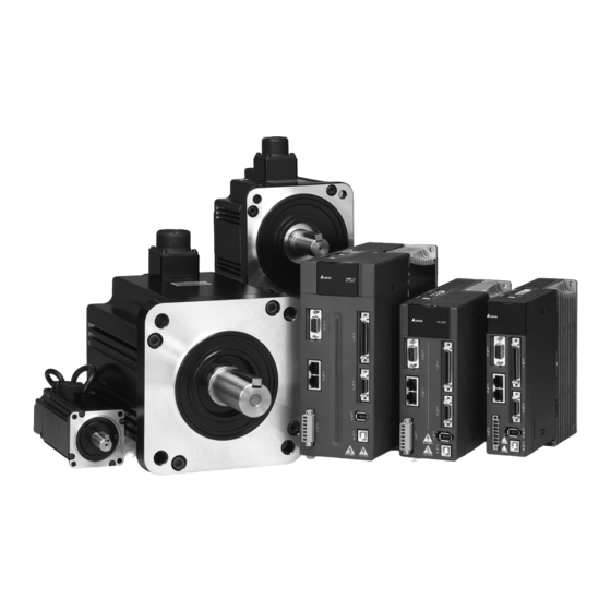
Delta ASDA-A2 Series User Manual
High resolution ac servo drive for network communication applications
Hide thumbs
Also See for ASDA-A2 Series:
- User manual (753 pages) ,
- Quick start manual (37 pages) ,
- Instruction sheet (12 pages)
Table of Contents
Advertisement
Quick Links
Advertisement
Table of Contents

Related Manuals for Delta ASDA-A2 Series


Summary of Contents for Delta ASDA-A2 Series
- Page 2 Thank you very much for purchasing DELTA’s AC servo products. This manual will be helpful in the installation, wiring, inspection, and operation of Delta AC servo drive and motor. Before using the product, please read this user manual to ensure correct use.
- Page 3 IGBT (Insulated Gate Bipolar Transistor). ASDA-A2 series drives can be used in industrial applications and for installation in an end-use enclosure that do not exceed the specifications defined in the ASDA-A2 series user manual (Drives, cables and motors are for use in a suitable enclosure with a minimum of a UL50 type 1 or NEMA 250 Type 1 rating).
- Page 4 Preface|ASDA-A2 Series Installation Do not install the product in a location that is outside the stated specification for the drive and motor. Failure to observe this caution may result in electric shock, fire, or personal injury. Wiring Connect the ground terminals to a class-3 ground (Ground resistance should not exceed 100 Ω). Improper grounding may result in electric shock or fire.
- Page 5 Preface|ASDA-A2 Series Main Circuit Terminal Wiring Please perform the wiring after the terminal blocks are all removed from the drive. Insert only one wire into one terminal on the terminal block. When inserting wires, please ensure that the conductors are not shorted to adjacent terminals or wires.
-
Page 6: Table Of Contents
Table of Contents Chapter 1 Unpacking Check and Model Explanation............. 1-1 Unpacking Check ........................1-1 Model Explanation........................1-2 1.2.1 Nameplate Information ..................... 1-2 1.2.2 Model Name Explanation ....................1-3 Servo Drive and Servo Motor Combinations................1-5 Servo Drive Features ......................1-6 Chapter 2 Installation and Storage.................. - Page 7 Table of Contents|ASDA-A2 Series Basic Wiring ..........................3-10 Input / Output Interface Connector -CN1 ................3-13 3.3.1 CN1 Terminal Identification ....................3-13 3.3.2 Signals Explanation of Connector CN1 ................3-15 3.3.3 User-defined DI and DO signals..................3-27 3.3.4 Wiring Diagrams of I/O Signals (CN1)................3-27 Encoder Connector CN2 ......................
- Page 8 Table of Contents|ASDA-A2 Series 4.3.2 Decimal Point Display....................... 4-3 4.3.3 Fault Message Display ..................... 4-3 4.3.4 Polarity Setting Display..................... 4-3 4.3.5 Monitor Setting Display..................... 4-4 General Function Operation....................4-7 4.4.1 Fault Code Display Operation ..................4-7 4.4.2 JOG Operation........................4-7 4.4.3...
- Page 9 Table of Contents|ASDA-A2 Series Chapter 6 Control Modes of Operation .................. 6-1 Control Modes of Operation ....................6-1 Position Control Mode......................6-3 6.2.1 Command Source of Position (Pt) Control Mode ............. 6-3 6.2.2 Command Source of Position (Pr) Control Mode ............. 6-7 6.2.3...
- Page 10 Table of Contents|ASDA-A2 Series 6.4.5 Timing Chart of Speed Control Mode................6-47 Control Modes Selection ......................6-48 6.5.1 Speed / Position Control Mode Selection................. 6-48 6.5.2 Speed / Torque Control Mode Selection ................6-49 6.5.3 Torque / Position Control Mode Selection................ 6-50 Others............................
- Page 11 Table of Contents|ASDA-A2 Series 7.10.2 Pr Path..........................7-21 7.11 Electronic Cam (E-CAM)......................7-23 7.11.1 CAPTURE Function......................7-31 7.11.2 COMPARE Function......................7-33 Chapter 8 Servo Parameters ....................8-1 Definition ..........................8-1 Parameter Summary ....................... 8-2 8.2.1 Parameters List by Group....................8-2 8.2.2...
- Page 12 Potential Cause and Corrective Actions ................. 11-6 11.3 Clearing Faults ........................11-24 Chapter 12 Specifications ......................12-1 12.1 Specifications of Servo Drive (ASDA-A2 Series) ..............12-1 12.2 Specifications of Servo Motors (ECMA Series) ..............12-4 12.3 Servo Motor Speed-Torque Curves (T-N Curves) ..............12-10 12.4...
-
Page 13: Revision
Due to constantly growing product range, technical improvement and alteration or changed texts, figures and diagrams, we reserve the right of this manual contained information change without prior notice. Coping or reproducing any part of this manual, without written consent of Delta Electronics Inc. is prohibited. Technical Support and Service Welcome to contact us or visit our web site (http://www.delta.com.tw/industrialautomation/) if you need any... -
Page 14: Chapter 1 Unpacking Check And Model Explanation
If any items are damaged or incorrect, please inform the distributor whom you purchased the product from or your local Delta sales representative. A complete and workable AC servo system should include the following parts: Part I : Delta standard supplied parts Servo drive Servo motor... -
Page 15: Model Explanation
Chapter 1 Unpacking Check and Model Explanation|ASDA-A2 Series power cable includes a green grounding cable. Please connect the green grounding cable to the ground terminal of the servo drive. One encoder cable, which is used to connect the encoder of servo motor to the CN2 terminal of servo drive. -
Page 16: Model Name Explanation
Chapter 1 Unpacking Check and Model Explanation|ASDA-A2 Series Serial Number Explanation 1.2.2 Model Name Explanation ASDA-A2 Series Servo Drive Second Feedback Signal Digital Input Type CANopen Extension Port (For full closed-loop control) M (Communication Type) U (Internal Position Control Type) - Page 17 Chapter 1 Unpacking Check and Model Explanation|ASDA-A2 Series ECMA Series Servo Motor NOTE Only frame size 180mm servo motors are available. Revision April, 2010...
-
Page 18: Servo Drive And Servo Motor Combinations
Chapter 1 Unpacking Check and Model Explanation|ASDA-A2 Series Servo Drive and Servo Motor Combinations The table below shows the possible combination of Delta ASDA-A2 series servo drives and ECMA series servo motors. (Please refer to Section 1.2 for model explanation) -
Page 19: Servo Drive Features
Chapter 1 Unpacking Check and Model Explanation|ASDA-A2 Series shown in the above table. If the drives which are designed according to the six multiple of rated current of motors are needed, please contact our distributors or your local Delta sales representative. Servo Drive Features... - Page 20 Chapter 1 Unpacking Check and Model Explanation|ASDA-A2 Series Top View Revision April, 2010...
- Page 21 Chapter 1 Unpacking Check and Model Explanation|ASDA-A2 Series Bottom View Revision April, 2010...
-
Page 22: Chapter 2 Installation And Storage
Chapter 2 Installation and Storage Installation Notes Please pay close attention on the following installation notes: Do not bend or strain the connection cables between servo drive and motor. When mounting the servo drive, make sure to tighten all screws to secure the drive in place. If the servo motor shaft is coupled directly to a rotating device ensure that the alignment specifications of the servo motor, coupling, and device are followed. -
Page 23: Installation Conditions
Chapter 2 Installation and Storage|ASDA-A2 Series Installation Conditions Operating Temperature ASDA-A2 Series Servo Drive 0°C to 55°C (32°F to 131°F) ECMA Series Servo Motor 0°C to 40°C (32°F to 104°F) The ambient temperature of servo drive for long-term reliability should be under 45°C (113°F). -
Page 24: Installation Procedure And Minimum Clearances
Chapter 2 Installation and Storage|ASDA-A2 Series Installation Procedure and Minimum Clearances Installation Procedure Incorrect installation may result in a drive malfunction or premature failure of the drive and or motor. Please follow the guidelines in this manual when installing the servo drive and motor. - Page 25 Chapter 2 Installation and Storage|ASDA-A2 Series Minimum Clearances Install a fan to increase ventilation to avoid ambient temperatures that exceed the specification. When installing two or more drives adjacent to each other please follow the clearances as shown in the following diagram.
- Page 26 Chapter 2 Installation and Storage|ASDA-A2 Series Side by Side Installation NOTE 1) The scale of the clearances does not match the dimensions as shown in the drawing above. In the event of any discrepancy between the clearances and the dimensions, the dimensions shall prevail.
-
Page 27: Molded-Case Circuit Breaker And Fuse Current Recommended Value
Chapter 2 Installation and Storage|ASDA-A2 Series Molded-case Circuit Breaker and Fuse Current Recommended Value Caution: Please use molded-case circuit breaker and fuse which are recognized by and comply with the UL or CSA standards. Model Name Breaker Fuse (Class T) - Page 28 By using an EMI filter with correct installation, much of the interference can be eliminated. It is recommended to use Delta’s EMI filter to have the best interference elimination performance.
- Page 29 Chapter 2 Installation and Storage|ASDA-A2 Series Figure 1 Saddle on both ends Saddle on one end Figure 2 Revision April, 2010...
- Page 30 Chapter 2 Installation and Storage|ASDA-A2 Series Dimensions Delta Part Number: 08TDT1W4S Delta Part Number: 11TDT1W4S Revision April, 2010...
- Page 31 Chapter 2 Installation and Storage|ASDA-A2 Series Delta Part Number: 20TDT1W4D Delta Part Number: RF075M43BA 125.0 60.0 (4.92) (2.36) 30.0 85.0 (1.18) (3.35) 15.0 (0.52) (0.22) 30.0 (1.18) 2-10 Revision April, 2010...
-
Page 32: Regenerative Resistor
Chapter 2 Installation and Storage|ASDA-A2 Series Regenerative Resistor Built-in Regenerative Resistor When the output torque of servo motor in reverse direction of motor rotation speed, it indicates that there is a regenerative power returned from the load to the servo drive. This power will be transmitted into the capacitance of DC Bus and result in rising voltage. - Page 33 Chapter 2 Installation and Storage|ASDA-A2 Series characteristics of the regenerative resistors, please check with the manufacturer. External Regenerative Resistor When using external regenerative resistor, connect it to P and C, and make sure the circuit between and D is open. We recommend the users should use the external regenerative resistor that the resistance value following the above table (Built-in Regenerative Resistor Specifications).
- Page 34 ( (7+1) × 1.68 - 8) / 0.4 = 27.2W. If the calculation result is smaller than regenerative power, we recommend the users to use the built-in 60W regenerative resistor. Usually the built-in regenerative resistor provided by ASDA-A2 series servo drives can meet the requirement of general application when the external load inertia is not excessive.
- Page 35 Chapter 2 Installation and Storage|ASDA-A2 Series Motor Rotation Speed External Load Torque Motor Output Torque Reverse Reverse Forward Forward Rotation Rotation Rotation Rotation External load torque in reverse direction: TL x Wr TL : External load torque For the safety, we strongly recommend the users should select the proper resistance value according to the load.
- Page 36 Chapter 2 Installation and Storage|ASDA-A2 Series When the servo motor runs with load, the allowable frequency will change according to the changes of the load inertia and rotation speed. Use the following equation to calculate the allowable frequency. times Allowable frequency when serv o motor run without load...
- Page 37 Chapter 2 Installation and Storage|ASDA-A2 Series Allowable frequency when the servo motor run without load (times/min) and uses external regenerative resistor Motor Capacity ECMA□□G 0.3kW 0.6kW 0.9kW Recommended Regenerative Resistor Specifications BR400W040 (400W 40Ω) BR1K0W020 (1kW 20Ω) When the regenerative resistor capacity is not enough, the users can connect to multiple the same capacity regenerative resistors in parallel to increase it.
- Page 38 Chapter 2 Installation and Storage|ASDA-A2 Series Delta Part Number:BR1K0W020(1kW 20Ω) MAX. WEIGHT(g) 2800 Delta Part Number:BR1K5W005(3kW 10Ω) 2-17 Revision April, 2010...
- Page 39 Chapter 2 Installation and Storage|ASDA-A2 Series This page intentionally left blank 2-18 Revision April, 2010...
-
Page 40: Chapter 3 Connections And Wiring
Chapter 3 Connections and Wiring This chapter provides information on wiring ASDA-A2 series products, the descriptions of I/O signals and gives typical examples of wiring diagrams. Connections 3.1.1 Connecting to Peripheral Devices Figure 3.1 Configuration Revision April, 2010... -
Page 41: Servo Drive Connectors And Terminals
Chapter 3 Connections and Wiring|ASDA-A2 Series 3.1.2 Servo Drive Connectors and Terminals Terminal Terminal Notes Identification Description Control circuit Used to connect single-phase AC control circuit power terminal depending on connecting servo drive model. Main circuit Used to connect three-phase AC main circuit power... - Page 42 Chapter 3 Connections and Wiring|ASDA-A2 Series Terminal Terminal Notes Identification Description USB connector Used to connect personal computer (PC or notebook). (Type B) Please refer to section 3.6 for details. (Optional Part) Position feedback signal connector Used to connect to linear scale or encoder to constitute a (for full-closed loop) full-closed loop.
-
Page 43: Wiring Methods
Chapter 3 Connections and Wiring|ASDA-A2 Series The shield of shielded twisted-pair cables should be connected to the SHIELD end (terminal marked ) of the servo drive. For the connectors and cables specifications, please refer to section 3.1.6 for details. 3.1.3 Wiring Methods For servo drives from 200W to 1.5kW the input power can be either single or three-phase. -
Page 44: Motor Power Cable Connector Specifications
Chapter 3 Connections and Wiring|ASDA-A2 Series Figure 3.3 Three-Phase Power Supply Connection (for all models) 3.1.4 Motor Power Cable Connector Specifications The boxes ( ) in the model names are for optional configurations. (Please refer to section 1.2 for model explanation.) - Page 45 Chapter 3 Connections and Wiring|ASDA-A2 Series Terminal Motor Model Name U, V, W / Electromagnetic Brake Connector Identification ECMA-G11303 S (300W) ECMA-E11305 S (500W) ECMA-G11306 S (600W) ECMA-G11309 S (900W) ECMA-C11010 S (1000W) ECMA-E11310 S (1000W) ECMA-E11315 S (1500W) ECMA-C11020 S (2000W)
-
Page 46: Encoder Connector Specifications
Chapter 3 Connections and Wiring|ASDA-A2 Series CASE GROUND BRAKE1 BRAKE2 Terminal Identification (Red) (White) (Black) (Green) (Yellow) (Blue) NOTE 1) The coil of brake has no polarity. The names of terminal identification are BRAKE1 (Yellow) and BRAKE2 (Blue). 2) The power supply for brake is DC24V. Never use it for VDD, the +24V source voltage. -
Page 47: Cable Specifications For Servo Drive
Chapter 3 Connections and Wiring|ASDA-A2 Series Terminal BRAID Reserved Reserved Reserved Reserved DC+5V Identification SHELD (Blue/ (Red & (Black & (Blue) Red/White) Black/White) Black) 3.1.6 Cable Specifications for Servo Drive Power Cable Power Cable - Wire Gauge AWG (mm Servo Drive and Servo Motor... - Page 48 Chapter 3 Connections and Wiring|ASDA-A2 Series Encoder Cable Encoder Cable - Wire Gauge AWG (mm Servo Drive Wire Size Wire Size Wire Size Wire Size ASD-A2-0121- 0.13 (AWG26) 10 core (4 pair) UL2464 3m (9.84ft.) ASD-A2-0221- 0.13 (AWG26) 10 core (4 pair) UL2464 3m (9.84ft.)
-
Page 49: Basic Wiring
Chapter 3 Connections and Wiring|ASDA-A2 Series Basic Wiring Figure 3.4 Basic Wiring Schematic of 400W and below models (Without built-in regenerative resistor) 3-10 Revision April, 2010... - Page 50 Chapter 3 Connections and Wiring|ASDA-A2 Series Figure 3.5 Basic Wiring Schematic of 750W to 4.5kW models (With built-in regenerative resistor and fan) 3-11 Revision April, 2010...
- Page 51 Chapter 3 Connections and Wiring|ASDA-A2 Series Figure 3.6 Basic Wiring Schematic of 5.5kW to 7.5kW models (With built-in fan but no regenerative resistor) 3-12 Revision April, 2010...
-
Page 52: Input / Output Interface Connector -Cn1
Chapter 3 Connections and Wiring|ASDA-A2 Series Input / Output Interface Connector -CN1 The CN1 Interface Connector provides access to three signal groups: General interface for the analog speed and torque control, encoder reference signal from the motor, pulse / direction inputs, and reference voltages. - Page 53 Chapter 3 Connections and Wiring|ASDA-A2 Series DO4+ Digital output 26 DO4- Digital output DO3- Digital output 27 DO5- Digital output DO3+ Digital output 28 DO5+ Digital output DO2- Digital output 29 /HPULSE High-speed DO2+ Digital output position pulse 30 DI8-...
-
Page 54: Signals Explanation Of Connector Cn1
Chapter 3 Connections and Wiring|ASDA-A2 Series 3.3.2 Signals Explanation of Connector CN1 The Tables 3.A, 3.B, & 3.C detail the three groups of signals of the CN1 interface. Table 3.A details the general signals. Table 3.B details the Digital Output (DO) signals and Table 3.C details the Digital Input (DI) signals. - Page 55 Chapter 3 Connections and Wiring|ASDA-A2 Series Wiring Diagram Signal Pin No Details (Refer to 3.3.4) VDD is the +24V source voltage provided by the drive. Maximum permissible current 500mA. COM+ is the common voltage rail of the Digital Input (DI) and Digital Output (DO) signals. When using VDD, VDD should be connected to COM+.
- Page 56 Chapter 3 Connections and Wiring|ASDA-A2 Series Pin No. Assigned Wiring Diagram (Default) DO Signal Control Details (Refer to 3.3.4) Mode ZSPD is activated when the drive senses the motor is equal to or below the Zero Speed Range setting as defined in parameter P1-38.
- Page 57 Chapter 3 Connections and Wiring|ASDA-A2 Series Pin No. Assigned Wiring Diagram (Default) DO Signal Control Details (Refer to 3.3.4) Mode Forward software limit. SPL is activated when the servo drive has detected that forward software (SCCWL) limit is reached. Internal position command completed output.
- Page 58 Chapter 3 Connections and Wiring|ASDA-A2 Series 2) The DO signals that do not have pin numbers in Tables 3.B are not default DO signals. If the users want to use these non-default DO signals, the users need to change the settings of parameters P2- 18 ~ P2-22.
- Page 59 Chapter 3 Connections and Wiring|ASDA-A2 Series Assigned Pin No. Wiring Diagram Control Details Signal (Default) (Refer to 3.3.4) Mode Pt, T, Tz, TCM0 Select the source of torque command: Pt-T, Pr- See table 3.F. TCM1 T, S-T Speed / Position mode switching...
- Page 60 Chapter 3 Connections and Wiring|ASDA-A2 Series Assigned Pin No. Wiring Diagram Control Details Signal (Default) (Refer to 3.3.4) Mode Event trigger command 1. Event trigger command 2. Event trigger command 3. (available for ASDA-A2 firmware version V1.008 sub04 or later) Event trigger command 4.
- Page 61 Chapter 3 Connections and Wiring|ASDA-A2 Series Table 3.E Source of Speed Command SPD1 SPD0 Parameters S mode: analog input Sz mode: 0 P1-09 P1-10 P1-11 Table 3.F Source of Torque Command TCM1 TCM0 Parameters T mode: analog input Tz mode: 0...
- Page 62 Chapter 3 Connections and Wiring|ASDA-A2 Series Signal Function Tz Pt-S Pt-T Pr-S Pr-T S-T Code Position command POS0 0x11 DI3 DI3 selection 0 (1~64) Position command POS1 0x12 DI4 DI4 selection 1 (1~64) Position command POS2 0x13 selection 2 (1~64)
- Page 63 Chapter 3 Connections and Wiring|ASDA-A2 Series Signal Function Tz Pt-S Pt-T Pr-S Pr-T S-T Code Reference “Home” ORGP 0x24 sensor Reverse operation torque limit (torque limit TLLM 0x25 function is valid only when P1-02 is enabled) Forward operation torque limit (torque limit...
- Page 64 Chapter 3 Connections and Wiring|ASDA-A2 Series Table 3.H Default DO signals and Control modes Signal Function Tz Pt-S Pt-T Pr-S Pr-T S-T Code SRDY 0x01 Servo ready DO1 DO1 DO1 DO1 DO1 DO1 DO1 DO1 DO1 DO1 DO1 0x02 Servo On...
- Page 65 Chapter 3 Connections and Wiring|ASDA-A2 Series Signal Function Tz Pt-S Pt-T Pr-S Pr-T S-T Code Output the status of SDO_5 0x35 bit05 of P4-06. Output the status of SDO_6 0x36 bit06 of P4-06. Output the status of SDO_7 0x37 bit07 of P4-06.
-
Page 66: User-Defined Di And Do Signals
Chapter 3 Connections and Wiring|ASDA-A2 Series 3.3.3 User-defined DI and DO signals If the default DI and DO signals could not be able to fulfill users’ requirements, there are still user- defined DI and DO signals. The setting method is easy and they are all defined via parameters. The user-defined DI and DO signals are defined via parameters P2-10 to P2-17 and P2-18 to P2-22. - Page 67 Chapter 3 Connections and Wiring|ASDA-A2 Series There are two kinds of pulse inputs, Line driver input and Open-collector input. Max. input pulse frequency of Line-driver input is 500kpps and max. input pulse frequency of Open-collector input is 200kpps. C3-1: Pulse input, for the use of internal power...
- Page 68 Chapter 3 Connections and Wiring|ASDA-A2 Series C4-2: High-speed pulse input (Line driver). It requires 5V power supply only. Never apply a 24V power supply. Caution: Ensure that the ground terminal of the controller and the servo drive should be connected to each other.
- Page 69 Chapter 3 Connections and Wiring|ASDA-A2 Series C7: Wiring of DO signal, for the use of external C8: Wiring of DO signal, for the use of external power supply, general load power supply, inductive load Use a relay or open-collector transistor to input signal.
- Page 70 Chapter 3 Connections and Wiring|ASDA-A2 Series C13: Encoder output signal (Line driver) C14: Encoder output signal (Photocoupler) C15: Encoder OCZ output Open-collector Z-pulse output) 3-31 Revision April, 2010...
-
Page 71: Encoder Connector Cn2
Chapter 3 Connections and Wiring|ASDA-A2 Series Encoder Connector CN2 Feedback to the amplifier of the UVW signals for commutation is via the ABZ encoder signal wires. Following rotor position sensing the amplifier automatically switches to encoding for commutation control. The 20-bit encoder is automatically multiplied to 1280000ppr for increased control accuracy. - Page 72 Chapter 3 Connections and Wiring|ASDA-A2 Series CN2 Terminal Signal Identification Drive Connector Motor Connector Terminal Military Quick PIN No. Description Color Identification Connector Connector Serial communication signal Blue input / output (+) Serial communication signal Blue/Black input / output (-)
-
Page 73: Serial Communication Connector Cn3
The servo drive can be connected to a PC or controller via this serial communication connector CN3. Users can operate the servo drive through PC software supplied by Delta. The communication connector/port of Delta servo drive can provide two common serial communication interfaces: RS-232 and RS-485 connection. -
Page 74: Connection Between Pc/Keypad And Connector Cn3
Chapter 3 Connections and Wiring|ASDA-A2 Series 3.5.2 Connection between PC and Connector CN3 3-35 Revision April, 2010... -
Page 75: Serial Communication Connector Cn4 (Usb)
The servo drive can be connected to a PC via this serial communication connector CN4. Users can operate the servo drive through PC software supplied by Delta. The USB transmission speed can reach up to 1MB. Therefore, the users can easily monitor the servo drive data in real time by using Data Scope function provided by Delta PC software. -
Page 76: Position Feedback Signal Connector Cn5 (For Full-Closed Loop)
Chapter 3 Connections and Wiring|ASDA-A2 Series Position Feedback Signal Connector CN5 (for Full-closed Loop) The servo drive can be connected to a linear scale or external encoder to constitute a full-closed loop via this position feedback signal connector CN5. In position mode, the pulse position commands given by the external controller just refer to the control loop structure of the external linear scale. -
Page 77: Canopen Communication Connector Cn6
Chapter 3 Connections and Wiring|ASDA-A2 Series CANopen Communication Connector CN6 CANopen Communication Connector CN6 is designed in accordance with CANopen DS301 and DS402 implementation. With this connector CN6, the servo drive can be connected to a CAN device so as to perform position, speed and torque control, or read and monitor the status of the servo drive through CANopen communication. - Page 78 Chapter 3 Connections and Wiring|ASDA-A2 Series Figure 3.13 Connecting more than one servo drives via CANopen communication 3-39 Revision April, 2010...
-
Page 79: Extension Digital Input Connector Cn7
Chapter 3 Connections and Wiring|ASDA-A2 Series Extension digital input connector CN7 ASDA-A2 series provides single-axis point-to-point position control function and the position numbers can be up to 64 points. When internal 8 programmable Digital Inputs (DI) which can be set via parameters P2-10 ~ P2-17 can not satisfied, the users can use this extension digital input connector CN7 to increase more digital inputs. -
Page 80: Standard Connection Example
400W and below drives do not provide built-in regenerative resistor. The coil of brake has no polarity. For extension digital inputs (DI) connections (CN7 is a optional part, not Delta standard supplied part.). For USB connection. It is used to connect to personal computer or notebook. -
Page 81: Position (Pr) Control Mode
400W and below drives do not provide built-in regenerative resistor. The coil of brake has no polarity. For extension digital inputs (DI) connections (CN7 is a optional part, not Delta standard supplied part.). For USB connection. It is used to connect to personal computer or notebook. -
Page 82: Speed Control Mode
400W and below drives do not provide built-in regenerative resistor. The coil of brake has no polarity. For extension digital inputs (DI) connections (CN7 is a optional part, not Delta standard supplied part.). For USB connection. It is used to connect to personal computer or notebook. -
Page 83: Torque Control Mode
400W and below drives do not provide built-in regenerative resistor. The coil of brake has no polarity. For extension digital inputs (DI) connections (CN7 is a optional part, not Delta standard supplied part.). For USB connection. It is used to connect to personal computer or notebook. -
Page 84: Canopen Communication Mode
Chapter 3 Connections and Wiring|ASDA-A2 Series 3.10.5 CANopen Communication Mode Please note: Please refer to C9 ~ C12 wiring diagrams (SINK / SOURCE mode) in section 3.3.4 (on page 3-30). 400W and below drives do not provide built-in regenerative resistor. - Page 85 Chapter 3 Connections and Wiring|ASDA-A2 Series This page intentionally left blank. 3-46 Revision April, 2010...
-
Page 86: Chapter 4 Display And Operation
Chapter 4 Display and Operation This chapter describes the basic operation of the digital keypad and the features it offers. Description of the Digital Keypad The digital keypad includes the display panel and function keys. The Figure 4.1 shows all of the features of the digital keypad and an overview of their functions. -
Page 87: Display Flowchart
Chapter 4 Display and Operation|ASDA-A2 Series Display Flowchart Figure 4.2 Keypad Operation When the power is applied to the AC servo drive, the LCD display will show the monitor function codes for approximately one second, then enter into the monitor mode. -
Page 88: Status Display
Chapter 4 Display and Operation|ASDA-A2 Series Status Display 4.3.1 Save Setting Display After the SET key is pressed, LCD display will show the following display messages for approx. one second according to different status. Display Message Description The setting value is saved correctly. [Saved) This parameter is read only. -
Page 89: Monitor Setting Display
Chapter 4 Display and Operation|ASDA-A2 Series 4.3.5 Monitor Setting Display When the AC servo drive is applied to power, the LCD display will show the monitor function codes for approximately one second and then enter into the monitor mode. In monitor mode, in order to change the monitor status, the users can press UP or DOWN arrow key or change parameter P0-02 directly to specify the monitor status. - Page 90 Chapter 4 Display and Operation|ASDA-A2 Series P0-02 Display Message Description Unit Setting Absolute pulse number relative to encoder (use Z phase as home). The value of Z phase home point is 0, and it can be the value from -5000 to +5000 pulses.
- Page 91 Chapter 4 Display and Operation|ASDA-A2 Series NOTE 1) Dec. represents Decimal display and Hex. represents Hexadecimal display. 2) The above display methods are both available in monitor mode and parameter setting mode. 3) All monitor variables are 32-bit data. The users can switch to high byte or low byte and display format (Dec.
-
Page 92: General Function Operation
Chapter 4 Display and Operation|ASDA-A2 Series General Function Operation 4.4.1 Fault Code Display Operation After entering the parameter mode P4-00 to P4-04 (Fault Record), press SET key to display the corresponding fault code history for the parameter. Please refer to the Figure 4.3. -
Page 93: Force Output Control Operation
Chapter 4 Display and Operation|ASDA-A2 Series Figure 4.4 4.4.3 Force Output Control Operation For testing, the digital outputs can be forced to be activated (ON) or inactivated (OFF) by using parameter P2-08 and P4-06. First, set P2-08 to 406 to enable the force output control function and then using P4-06 to force the digital outputs to be activated. -
Page 94: Di Diagnosis Operation
Chapter 4 Display and Operation|ASDA-A2 Series Figure 4.6 NOTE 1) As the display of P4-06 is hexadecimal, 0(zero) of the fifth digit will not show on the LED display. 4.4.4 DI Diagnosis Operation Following the setting method in Figure 4.7 can perform DI diagnosis operation (parameter P4-07, Input Status). -
Page 95: Do Diagnosis Operation
Chapter 4 Display and Operation|ASDA-A2 Series Figure 4.7 4.4.5 DO Diagnosis Operation Following the setting method in Figure 4.8 can perform DO diagnosis operation (parameter P4-09, Output Status Display). According to the ON and OFF status of the digital outputs DO1 to DO5, the corresponding status will display on the servo drive LED display. -
Page 96: Chapter 5 Trial Run And Tuning Procedure
Chapter 5 Trial Run and Tuning Procedure This chapter, which is divided into two parts, describes trial run for servo drive and motor. One part is to introduce the trial run without load, and the other part is to introduce trial run with load. Ensure to complete the trial run without load first before performing the trial run with load. - Page 97 If there is no contact sound or there be any unusual noises when the relay of the servo drive is operating, please contact your distributor for assistance or contact with Delta. Check for abnormal conditions of the power indicators and LED display. If there is any abnormal condition of the power indicators and LED display, please contact your distributor for assistance or contact with Delta.
-
Page 98: Applying Power To The Drive
Chapter 5 Trial Run and Tuning Procedure|ASDA-A2 Series Applying Power to the Drive The users please observe the following steps when applying power supply to the servo drive. 1. Please check and confirm the wiring connection between the drive and motor is correct. - Page 99 Chapter 5 Trial Run and Tuning Procedure|ASDA-A2 Series 1) When display shows: Overvoltage: The main circuit voltage has exceeded its maximum allowable value or input power is error (Incorrect power input). Corrective Actions: Use voltmeter to check whether the main circuit input voltage falls within the rated input voltage.
- Page 100 Chapter 5 Trial Run and Tuning Procedure|ASDA-A2 Series If it is necessary to use “Emergency Stop (EMGS)” as input signal, the users only need to confirm that which of digital inputs DI1 ~ DI8 is set to “Emergency Stop (EMGS)” and check if the digital input signal is ON (It should be activated).
- Page 101 NOTE 1) If there are any unknown fault codes and abnormal display when applying power to the drive or servo on is activated (without giving any command), please inform the distributor or contact with Delta for assistance. Revision April, 2010...
-
Page 102: Jog Trial Run Without Load
Chapter 5 Trial Run and Tuning Procedure|ASDA-A2 Series JOG Trial Run without Load It is very convenient to use JOG trial run without load to test the servo drive and motor as it can save the wiring. The external wiring is not necessary and the users only need to connect the digital keypad to the servo drive. - Page 103 Chapter 5 Trial Run and Tuning Procedure|ASDA-A2 Series In the example below, the JOG speed is adjusted from 20r/min (Default setting) to 100r/min. Revision April, 2010...
-
Page 104: Speed Trial Run Without Load
P2-15 to P2-17 and P2-36 to P2-41 to 0 (Disabled) in advance. All the digital inputs of Delta ASDA-A2 series are user-defined, and the users can set the DI signals freely. Ensure to refer to the definitions of DI signals before defining them (For the description of DI signals, please refer to Table 8.A in Chapter 8). - Page 105 Chapter 5 Trial Run and Tuning Procedure|ASDA-A2 Series The speed command is selected by SPD0, SPD1. Please refer to the following table: DI signal of CN1 Speed Command Source Content Range Command No. SPD1 SPD0 External analog Voltage between V-REF...
-
Page 106: Position Trial Run Without Load
P2-15 to P2-17 and P2-36 to P2-41 to 0 (Disabled) in advance. All the digital inputs of Delta ASDA-A2 series are user-defined, and the users can set the DI signals freely. Ensure to refer to the definitions of DI signals before defining them (For the description of DI signals, please refer to Table 8.A in Chapter 8). - Page 107 Chapter 5 Trial Run and Tuning Procedure|ASDA-A2 Series Please refer to the following table for 64 groups of position commands and position command selection from POS0 to POS5. Position POS5 POS4 POS3 POS2 POS1 POS0 CTRG Parameters Command P6-00 P6-01...
-
Page 108: Tuning Procedure
Chapter 5 Trial Run and Tuning Procedure|ASDA-A2 Series Tuning Procedure Table 5.A Estimate the ratio of Load Inertia to Servo Motor Inertia (J_load /J_motor): JOG Mode Display Tuning Procedure After wiring is completed, when power in connected to the AC servo drive, the right side display will show on the LCD display. -
Page 109: Tuning Flowchart
Chapter 5 Trial Run and Tuning Procedure|ASDA-A2 Series 5.6.1 Tuning Flowchart 5-14 Revision April, 2010... -
Page 110: Load Inertia Estimation Flowchart
Chapter 5 Trial Run and Tuning Procedure|ASDA-A2 Series 5.6.2 Load Inertia Estimation Flowchart 5-15 Revision April, 2010... -
Page 111: Auto Mode Tuning Flowchart
Chapter 5 Trial Run and Tuning Procedure|ASDA-A2 Series 5.6.3 Auto Mode Tuning Flowchart Set P2-32 to 1 (1: Auto Mode [Continuous adjustment] ) The servo drive will continuously estimate the system inertia, save the measured load inertia value automatically and memorized in P1-37 every 30 minutes by referring to the frequency response settings of P2-31. -
Page 112: Semi-Auto Mode Tuning Flowchart
Chapter 5 Trial Run and Tuning Procedure|ASDA-A2 Series 5.6.4 Semi-Auto Mode Tuning Flowchart Set P2-32 to 2 (2: Semi-Auto Mode [Non-continuous adjustment] ) The servo drive will continuously perform the adjustment for a period of time. After the system inertia becomes stable, it will stop estimating the system inertia, save the measured load inertia value automatically, and memorized in P1-37. - Page 113 Chapter 5 Trial Run and Tuning Procedure|ASDA-A2 Series NOTE 1) When bit0 of P2-33 is set to 1, it indicates that the system inertia estimation of semi-auto mode has been completed and the measured load inertia value is saved and memorized in P1-37 automatically.
-
Page 114: Limit Of Load Inertia Estimation
Chapter 5 Trial Run and Tuning Procedure|ASDA-A2 Series 5.6.5 Limit of Load Inertia Estimation The accel. / decel. time for reaching 2000r/min must be below 1 second. The rotation speed must be above 200 r/min. The load inertia must be 100 multiple or less of motor inertia. The change of external force and the inertia ratio can not be too much. - Page 115 Chapter 5 Trial Run and Tuning Procedure|ASDA-A2 Series NOTE 1) Parameters P2-44 and P2-46 are used to set notch filter attenuation rate. If the resonance can not be suppressed when the setting values of P2-44 and P2-46 are set to 32bB (the maximum value), please decrease the speed loop frequency response.
-
Page 116: Mechanical Resonance Suppression Method
Chapter 5 Trial Run and Tuning Procedure|ASDA-A2 Series 5.6.6 Mechanical Resonance Suppression Method In order to suppress the high frequency resonance of the mechanical system, ASDA-A2 series servo drive provides three notch filters (resonance suppression parameters) for resonance suppression. Two notch filters can be set to suppress the resonance automatically. -
Page 117: Relationship Between Tuning Modes And Parameters
Chapter 5 Trial Run and Tuning Procedure|ASDA-A2 Series 5.6.7 Relationship between Tuning Modes and Parameters AutoSet Tuning Mode P2-32 User-defined Parameter Gain Value Parameter P1-37 (Ratio of Load Inertia to Servo Motor Inertia [J_load / J_motor]) P2-00 (Proportional Position Loop Gain) -
Page 118: Gain Adjustment In Manual Mode
Chapter 5 Trial Run and Tuning Procedure|ASDA-A2 Series 5.6.8 Gain Adjustment in Manual Mode The position and speed frequency response selection is depending on and determined by the the control stiffness of machinery and conditions of applications. Generally, high reponsiveness is essential for the high frequency positioning control of mechanical facilities and the applications of high precision process system. - Page 119 Chapter 5 Trial Run and Tuning Procedure|ASDA-A2 Series KVI, Parameter P2-06 Speed Integral Compensation If the setting value of KVI is higher, the capability of decreasing the speed control deviation is better. However, if the setting value is over high, it may easily result in the vibration of machinery system.
-
Page 120: Chapter 6 Control Modes Of Operation
Chapter 6 Control Modes of Operation Control Modes of Operation The Delta ASDA-A2 series can be programmed to provide six single, eight dual modes and two multiple modes of operation. Their operation and description is listed in the following table. - Page 121 Chapter 6 Control Modes of Operation|ASDA-A2 Series Mode Mode Code Description Either Pt or Pr control mode can be selected via the Pt-Pr Digital Inputs (DI). Either Pt or Pr or S control mode can be selected via Pt-Pr-S the Digital Inputs (DI).
-
Page 122: Position Control Mode
The max. input frequency for the external pulse command is 4MKpps. In order to provide a convenient position control function, Delta servo drive provides 64 internal preset parameters for position control. There are two setting methods of internal parameters, one is to set different position command into these 64 internal parameters before operation and then use POS0~POS5 of DI signals of CN1 to perform positioning control. - Page 123 Chapter 6 Control Modes of Operation|ASDA-A2 Series A: Input pulse type 0: AB phase pulse (4x) (Quadrature Input) 1: Clockwise (CW) + Counterclockwise(CCW) pulse 2: Pulse + Direction 3: Other settings: not used B: Input pulse filter This setting is used to suppress or reduce the chatter caused by the noise, etc. However, if the instant input pulse filter frequency is over high, the frequency that exceeds the setting value will be regarded as noise and filtered.
- Page 124 Chapter 6 Control Modes of Operation|ASDA-A2 Series C: Input polarity Logic Pulse Type Forward Reverse AB phase pulse CW + CCW Positive pulse Logic Pulse + Direction AB phase pulse Negative CW + CCW Logic pulse Pulse + Direction Max. input Min.
- Page 125 Chapter 6 Control Modes of Operation|ASDA-A2 Series D: Source of pulse command Setting Input pulse interface Remark value Open collector for CN1 Terminal Identification: low-speed pulse PULSE, SIGN Line driver for CN1 Terminal Identification: high-speed pulse PULSE_D, SIGN_D The source of pulse command can also be determined by digital input, PTCMS. When the digital input function is used, the source of pulse command is from digital input.
-
Page 126: Command Source Of Position (Pr) Control Mode
Chapter 6 Control Modes of Operation|ASDA-A2 Series 6.2.2 Command Source of Position (Pr) Control Mode The command sources of Pr mode are (P6-00, P6-01) ~ (P7-26, P7-27) these 64 built-in parameters. Using with external I/O signals (CN1, POS 0 to POS 5 and CTRG) can select one of the 64 built-in parameters to be position command. -
Page 127: Structure Of Position Control Mode
Using parameter can select Pr mode and Pt mode. Electronic gear ratio can be set in both two modes to set proper position revolution. ASDA-A2 series servo drives also provide S-curve and low-pass filter, which are used whenever the motor and load need to be operated more smoothly. As for the information of electronic gear ratio, S-curve and low-pass filter, please refer to the following sections 6.2.4, 6.2.5 and 6.2.6. -
Page 128: S-Curve Filter For Position Control
Chapter 6 Control Modes of Operation|ASDA-A2 Series Pulse Inhibit Input Function (INHIBIT) This function is activated via digital inputs (Please refer to parameter P2-10 ~ P2-17 and DI INHP in Table 8.A).When the drive is in position mode, if INHP is activated, the external pulse input command is not valid and the motor will stop (Please note that only DI8 supports this function). - Page 129 Chapter 6 Control Modes of Operation|ASDA-A2 Series Relevant Parameters: P1 - 34 TACC Acceleration Time Address: 0144H, 0145H Default: 200 Related Section: Section 6.3.3, Applicable Control Mode: S Unit: msec Range: 1 ~ 65500 Data Size: 16-bit Display Format: Decimal...
- Page 130 Chapter 6 Control Modes of Operation|ASDA-A2 Series P1 - 35 TDEC Deceleration Time Address: 0146H, 0147H Default: 200 Related Section: Section 6.3.3, Applicable Control Mode: S Unit: msec Range: 1 ~ 65500 Data Size: 16-bit Display Format: Decimal Settings: This parameter is used to determine the acceleration time to accelerate from 0 to its rated motor speed.
-
Page 131: Electronic Gear Ratio
Chapter 6 Control Modes of Operation|ASDA-A2 Series TSL: P1-36, Accel /Decel S-curve Total acceleration time = TACC + TSL Total deceleration time = TDEC + TSL The functions of parameters P1-34, P1-35 and P1-36 are each individual. When P1-36 is set to 0 (Disabled), the settings of P1-34, P1-35 are still effective. - Page 132 Chapter 6 Control Modes of Operation|ASDA-A2 Series Data Size: 32-bit Display Format: Decimal Settings: This parameter is used to set the denominator of the electronic gear ratio. The numerator of the electronic gear ratio is set by P1-44. P2-60 ~ P2-62 are used to set the additional numberators.
-
Page 133: Low-Pass Filter
Chapter 6 Control Modes of Operation|ASDA-A2 Series 6.2.6 Low-pass Filter Relevant parameters: Smooth Constant of Position Command (Low- P1 - 08 PFLT Address: 0110H, 0111H pass Filter) Default: 0 Related Section: Section 6.2.6 Applicable Control Mode: Pt/Pr Unit: 10msec Range: 0 ~ 1000 (0: Disabled) -
Page 134: Position Loop Gain Adjustment
Chapter 6 Control Modes of Operation|ASDA-A2 Series 6.2.8 Position Loop Gain Adjustment Before performing position control (setting position control block diagram), the users should complete the speed control setting by using Manual mode (parameter P-32) since the position loop contains speed loop. - Page 135 Chapter 6 Control Modes of Operation|ASDA-A2 Series P2 - 02 Position Feed Forward Gain Address: 0204H, 0205H Default: 50 Related Section: Section 6.2.8 Applicable Control Mode: Pt, Pr Unit: % Range: 0 ~ 100 Data Size: 16-bit Display Format: Decimal Settings: This parameter is used to set the feed forward gain when executing position control command.
-
Page 136: Low-Frequency Vibration Suppression
Chapter 6 Control Modes of Operation|ASDA-A2 Series 6.2.9 Low-frequency Vibration Suppression If the stiffness of the mechanical system is not sufficient, after the positioning command has completed, continuous vibration of the mechanical system may occur still even when the motor has almost stopped. - Page 137 Chapter 6 Control Modes of Operation|ASDA-A2 Series Please note: 1. When P1-26 and P1-28 are both set to 0, it indicates that the system could not find the frequency. Please check the setting value of P1-30 because when the setting value of P1-30 is too high, it may causes that the frequency becomes difficult to be found.
- Page 138 Chapter 6 Control Modes of Operation|ASDA-A2 Series Settings: 0: Normal mode (Disable Auto Low-frequency Vibration Suppression Mode). 1: Auto mode (Enable Auto Low-frequency Vibration Suppression Mode). Explanation: If P1-29 is set to 0, the setting of low-frequency vibration suppression is fixed and will not change automatically.
- Page 139 Chapter 6 Control Modes of Operation|ASDA-A2 Series Relevant parameters: P1 - 25 VSF1 Low-frequency Vibration Suppression (1) Address: 0132H, 0133H Default: 100.0 Related Section: Section 6.2.9 Applicable Control Mode: Pt/Pr Unit: Hz Range: 1.0 ~ 100.0 Data Size: 16-bit Display Format: Decimal Settings: This parameter is used to set the first group of the low-frequency of mechanical system.
- Page 140 Chapter 6 Control Modes of Operation|ASDA-A2 Series P1 - 28 VSG2 Low-frequency Vibration Suppression Gain (2) Address: 0138H, 0139H Default: 0 Related Section: Section 6.2.9 Applicable Control Mode: Pt/Pr Unit: - Range: 0 ~ 9 (0: Disable the function of P1-27)
-
Page 141: Speed Control Mode
The speed control mode (S or Sz) is usually used on the applications of precision speed control, such as CNC machine, etc. ASDA-A2 series servo drives support two kinds of command sources in speed control mode. One is external analog signal and the other is internal parameter. The external analog signal is from external voltage input and it can control the speed of servo motor. -
Page 142: Structure Of Speed Control Mode
Chapter 6 Control Modes of Operation|ASDA-A2 Series and GND. The setting range of the input voltage is from -10V to +10V and the corresponding motor speed is adjustable (Please see parameter P1-40). When at least one of SPD0 and SPD1 is not 0 (OFF), the speed command is internal parameter (P1-09 to P1-11). -
Page 143: Smoothing Strategy Of Speed Control Mode
ASDA-A2 series servo drives also support the time calculation of completing speed command. T (ms) is the operation (running) time. S (r/min) is absolute speed command, i.e. the absolute value (the result) after starting speed subtracts the final speed. - Page 144 Chapter 6 Control Modes of Operation|ASDA-A2 Series Relevant parameters: P1 - 34 TACC Acceleration Time Address: 0144H, 0145H Default: 200 Related Section: Section 6.3.3, Applicable Control Mode: S Unit: msec Range: 1 ~ 65500 Data Size: 16-bit Display Format: Decimal...
- Page 145 Chapter 6 Control Modes of Operation|ASDA-A2 Series P1 - 35 TDEC Deceleration Time Address: 0146H, 0147H Default: 200 Related Section: Section 6.3.3, Applicable Control Mode: S Unit: msec Range: 1 ~ 65500 Data Size: 16-bit Display Format: Decimal Settings: This parameter is used to determine the acceleration time to accelerate from 0 to its rated motor speed.
- Page 146 3. If the control of the servo motor is achieved via internal parameters, the command curve should be defined by the users. Analog Speed Command S-curve Filter ASDA-A2 series servo drives also provide Analog Speed Command S-curve Filter for the smoothing in response to a sudden analog input signal. Speed (rpm)
-
Page 147: Analog Speed Input Scaling
Chapter 6 Control Modes of Operation|ASDA-A2 Series Relevant parameters: Accel / Decel Smooth Constant of Analog Speed P1 - 06 SFLT Address: 010CH, 010DH Command (Low-pass Filter) Default: 0 Related Section: Section 6.3.3 Applicable Control Mode: S Unit: msec Range: 0 ~ 1000 (0: Disabled) -
Page 148: Timing Chart Of Speed Control Mode
Chapter 6 Control Modes of Operation|ASDA-A2 Series Relevant parameters: P1 - 40▲ Max. Analog Speed Command or Limit Address: 0150H, 0151H Default: rated speed Related Section: Section 6.3.4 Applicable Control Mode: S, T Unit: r/min Range: 0 ~ 10000 Data Size: 16-bit... -
Page 149: Speed Loop Gain Adjustment
Chapter 6 Control Modes of Operation|ASDA-A2 Series 6.3.6 Speed Loop Gain Adjustment The function and structure of speed control mode is shown as the figure below: There are two turning modes of gain adjustment: Manual and Auto modes. The gain of ASDA-A2 series servo drives can be adjusted by using any one of two tuning modes. - Page 150 Chapter 6 Control Modes of Operation|ASDA-A2 Series Explanation of manual mode: 1. When P2-32 is set to mode#0, the setting value of P2-00, P2-02, P2-04, P2-06, P2-07, P2-25 and P2-26 can be user-defined. When switching mode #1 or #2 to #0, the setting value of P2-00, P2-02, P2-04, P2-06, P2-07, P2-25 and P2-26 will change to the value that measured in #1 auto-tuning mode or #2 semi-auto tuning mode.
- Page 151 Chapter 6 Control Modes of Operation|ASDA-A2 Series Relevant parameters: P2 - 04 Proportional Speed Loop Gain Address: 0208H, 0209H Default: 500 Related Section: Section 6.3.6 Applicable Control Mode: ALL Unit: rad/s Range: 0 ~ 8191 Data Size: 16-bit Display Format: Decimal Settings: This parameter is used to set the speed loop gain.
- Page 152 Chapter 6 Control Modes of Operation|ASDA-A2 Series When using speed smooth command, increase gain can improve speed track deviation. When not using speed smooth command, decrease gain can improve the resonance condition of mechanical system. In theory, stepping response can be used to explain proportional gain (KVP), integral gain (KVI) and feed forward gain (KVF).
- Page 153 Chapter 6 Control Modes of Operation|ASDA-A2 Series Time Domain 6-34 Revision April,2010...
- Page 154 Chapter 6 Control Modes of Operation|ASDA-A2 Series In general, the equipment, such as spectrum analyzer is needed and used to analyze when using frequency domain method and the users also should have this kind of analysis technology. However, when using time domain method, the users only need to prepare an oscilloscope. Therefore, the general users usually use time domain method with the analog DI/DO terminal provided by the servo drive to adjust what is called as PI (Proportional and Integral) type controller.
-
Page 155: Resonance Suppression
Chapter 6 Control Modes of Operation|ASDA-A2 Series 6.3.7 Resonance Suppression The resonance of mechanical system may occur due to excessive system stiffness or frequency response. However, this kind of resonance condition can be improved, suppressed, even can be eliminated by using low-pass filter (parameter P2-25) and notch filter (parameter P2-23, P2-24) without changing control parameter. - Page 156 Chapter 6 Control Modes of Operation|ASDA-A2 Series P2 - 43 NCF2 Notch Filter 2 (Resonance Suppression) Address: 0256H, 0257H Default: 1000 Related Section: Section 6.3.7 Applicable Control Mode: ALL Unit: Hz Range: 50 ~ 2000 Data Size: 16-bit Display Format: Decimal Settings: This parameter is used to set second resonance frequency of mechanical system.
- Page 157 Chapter 6 Control Modes of Operation|ASDA-A2 Series This parameter is used to set third resonance frequency of mechanical system. It can be used to suppress the resonance of mechanical system and reduce the vibration of mechanical system. If P2-45 is set to 0, this parameter is disabled.
- Page 158 Chapter 6 Control Modes of Operation|ASDA-A2 Series There are two groups of notch filters provided by ASDA-A2 series. The first group of notch filter is P2-43 and P2-44, and the second group of notch filter is P2-45 and P2-46. When there is resonance, please set P2-47 to 1 or 2 (Auto mode), and then the servo drive will find resonance frequency and suppress the resonance automatically.
- Page 159 Chapter 6 Control Modes of Operation|ASDA-A2 Series Settings of P2-47 Current Value Desired Value Function Clear the setting value of P2-43 ~ P2-46 and enable auto resonance suppression function. Clear the setting value of P2-43 ~ P2-46 and enable auto resonance suppression function.
- Page 160 Chapter 6 Control Modes of Operation|ASDA-A2 Series 6-41 Revision April, 2010...
- Page 161 Chapter 6 Control Modes of Operation|ASDA-A2 Series Low-pass filter Please use parameter P2-25. The figure below shows the resonant open-loop gain. Gain Frequency When the low-pass filter (parameter P2-25) is adjusted from 0 to high value, the value of Low-pass frequency (BW) will become smaller (see the figure below).
- Page 162 Chapter 6 Control Modes of Operation|ASDA-A2 Series Use Notch Filter to suppress resonance Resonance Resonance conditions Gain Point Gain Gain is suppressed Notch Filter Low-pass Low-pass Attenuation Frequency Frequency Rate P2-24 Frequency Frequency Resonance Resonance Resonance Frequency Frequency Frequency .
-
Page 163: Torque Control Mode
The torque control mode (T or Tz) is usually used on the applications of torque control, such as printing machine, spinning machine, twister, etc. Delta ASDA-A2 series servo drives support two kinds of command sources in torque control mode. One is external analog signal and the other is internal parameter. -
Page 164: Structure Of Torque Control Mode
Chapter 6 Control Modes of Operation|ASDA-A2 Series 6.4.2 Structure of Torque Control Mode Basic Structure: The toque command processing is used to select the command source of torque control according to chapter 6.4.1, including max. analog torque command (parameter P1-41) and smoothing strategy of torque control mode. -
Page 165: Smoothing Strategy Of Torque Control Mode
Chapter 6 Control Modes of Operation|ASDA-A2 Series 6.4.3 Smoothing Strategy of Torque Control Mode Relevant parameters: Smooth Constant of Analog Torque Command P1 - 07 TFLT Address: 010EH, 010FH (Low-pass Filter) Default: 0 Related Section: Section 6.4.3 Applicable Control Mode: T... - Page 166 Chapter 6 Control Modes of Operation|ASDA-A2 Series Relevant parameters: P1 - 41▲ Max. Analog Torque Command or Limit Address: 0152H, 0153H Default: 100 Related Section: Section 6.4.4 Applicable Control Mode: ALL Unit: % Range: 0 ~ 1000 Data Size: 16-bit...
-
Page 167: Control Modes Selection
Chapter 6 Control Modes of Operation|ASDA-A2 Series Control Modes Selection Except signal control mode operation, ASDA-A2 series servo drives also provide many dual and multiple modes for the users to select. 1) Speed / Position mode selection: Pt-S, Pr-S, Pt-Pr 2)... -
Page 168: Speed / Torque Control Mode Selection
Chapter 6 Control Modes of Operation|ASDA-A2 Series The timing chart of speed / position control mode selection is shown as the figure below: CTRG POS0-2 NOT CARE POS0-2 VALID POS0-2 NOT CARE SPD0~1 NOT CARE SPD0-1 VALID SPD0-1 VALID Speed control mode... -
Page 169: Torque / Position Control Mode Selection
Chapter 6 Control Modes of Operation|ASDA-A2 Series 6.5.3 Torque / Position Control Mode Selection Pt-T Mode / Pr-T Mode: The command source of Pt-T mode is from external input pulse. The command source of Pr-T mode is from internal parameters (P6-00 to P7-27). The torque command can be the external input pulse or internal parameters (P1-12 to P1-14). -
Page 170: Others
Chapter 6 Control Modes of Operation|ASDA-A2 Series Others 6.6.1 Speed Limit The max. servo motor speed can be limited by using parameter P1-55 no matter in position, speed or torque control mode. The command source of speed limit command is the same as speed command. It can be the external analog voltage but also can be internal parameters (P1-09 to P1-11). -
Page 171: Analog Monitor
Chapter 6 Control Modes of Operation|ASDA-A2 Series 6.6.3 Analog Monitor Users can use analog monitor to observe the required analog voltage signals. ASDA-A2 series servo drives provide two analog channels, they are PIN No. 15 and 16 of CN1 connector. The parameters relative to analog monitor are shown below. - Page 172 Chapter 6 Control Modes of Operation|ASDA-A2 Series P1 - 03 AOUT Pulse Output Polarity Setting Address: 0106H, 0107H Default: 0 Related Section: Section 3.3.3 Applicable Control Mode: ALL Unit: N/A Range: 0 ~ 13 Data Size: 16-bit Display Format: Hexadecimal...
- Page 173 Chapter 6 Control Modes of Operation|ASDA-A2 Series P1 - 05 MON2 Analog Monitor Output Proportion 2 (CH2) Address: 010AH, 010BH Default: 100 Related Section: Section 6.4.4 Applicable Control Mode: ALL Unit: % (full scale) Range: 0 ~ 100 Data Size: 16-bit...
-
Page 174: Electromagnetic Brake
The maximum output voltage range of analog monitor output is ±8V. If the output voltage exceed its limit, it is still limited within the range of ±8V. The revolution provided by ASDA-A2 series servo drives is 10bit, approximated to 13mv/LSB. 6.6.4 Electromagnetic Brake When the servo drive is operating, if the digital output BRKR is set to Off, it indicates the electromagnetic brake is disabled and motor is stop running and locked. - Page 175 Chapter 6 Control Modes of Operation|ASDA-A2 Series BRKR output timing explanation: 1. When Servo Off (when DI SON is not activated), the BRKR output goes Off (electromagnetic brake is locked) after the delay time set by P1-43 is reached and the motor speed is still higher than the setting value of P1-38.
- Page 176 Chapter 6 Control Modes of Operation|ASDA-A2 Series The timing charts of control circuit power and main circuit power: L1, L2 Control Circuit Power 1 sec Control Circuit Power > 0msec R, S, T Main Circuit Power 800ms BUS Voltage READY...
- Page 177 Chapter 6 Control Modes of Operation|ASDA-A2 Series This page intentionally left blank. 6-58 Revision April,2010...
-
Page 178: Chapter 7 Motion Control Function
Chapter 7 Motion Control Function Available Motion Control Functions ASDA-A2 series provides the following motion control functions: 1) Pr mode for single-axis motion control 2) CAPTURE / COMPARE functions Electronic CAM (E-CAM) function Servo Drive Information The information of the servo drive includes: 1. Servo Parameters; 2. Monitor Variables; 3. Data Array Please refer to the following table below. -
Page 179: Monitor Variables
Chapter 7 Motion Control Function|ASDA-A2 Series 7.2.1 Monitor Variables Please refer to the following table for the explanation of monitor variables: Item Explanation Variable Each monitor variable has one corresponding code. The parameter P0-02 is used to Code set this code and monitor the monitor variable. - Page 180 Chapter 7 Motion Control Function|ASDA-A2 Series Explanation of monitor variables: Monitor Variable / Code Explanation Attribute Feedback position Motor feedback – current position. Unit is user unit, PUU. (00h) (PUU) Position command – current position. Unit is user unit, PUU.
- Page 181 Chapter 7 Motion Control Function|ASDA-A2 Series Monitor Variable / Code Explanation Attribute Resonance frequency of the mechanical system. There are two groups of resonance frequency: F1 and F2 When reading the drive status through the keypad, pressing SHIFT key can switch the display of F1 and F2.
- Page 182 Chapter 7 Motion Control Function|ASDA-A2 Series Monitor Variable / Code Explanation Attribute Feedback speed (Instant) Actual motor speed. Unit is 0.1r/min. (33h) D1 Dec Feedback speed Actual motor speed. Unit is 0.1r/min. (Filter) (34h) (The low-pass filter function is used.)
- Page 183 Chapter 7 Motion Control Function|ASDA-A2 Series Monitor Variable / Code Explanation Attribute In Pr mode, it is the terraced speed curve drawn up according to Speed command of Pr target speed / accel & decel time / position move (before using S-...
-
Page 184: Data Array
Chapter 7 Motion Control Function|ASDA-A2 Series 7.2.2 Data Array ASDA-A2 series provides many motion control functions, such as Capture, Compare and E-CAM. However, additional memory spaces become necessary when using these functions. Therefore, ASDA- A2 series reserves one block of internal consecutive memory space, data array for saving the data of Capture, Compare and E-CAM functions. - Page 185 Chapter 7 Motion Control Function|ASDA-A2 Series Relevant Parameters for Data Array Parameter Name Explanation When reading data through the keypad: Read the content specified by P5-11. After read operation is completed, the address of P5-11 will increase 1 automatically. When writing data through the keypad: This parameter can not be written through the keypad.
- Page 186 Chapter 7 Motion Control Function|ASDA-A2 Series Press SET key at the second time, the display will show the 200th data saved in address 12. Pressing MODE key can exit P5-13. Press SET key at the first time, the display will show the 300th data saved in address 13. Pressing MODE key can exit P5-13.
- Page 187 Chapter 7 Motion Control Function|ASDA-A2 Series Then, read the data of the specified address by using communication command 0x03. Please refer to the table below to set communication command. Communication command: Response Data Read data array P5-11 P5-12 P5-13 Starting...
-
Page 188: Motion Axis
Chapter 7 Motion Control Function|ASDA-A2 Series Motion Axis Motion axis is a counter within the servo drive which is used to count the data of absolute position (32-bit integer). The available motion axes are introduced in the following table. Read (R) /... -
Page 189: Pr Mode Introduction
Chapter 7 Motion Control Function|ASDA-A2 Series Pr Mode Introduction Pr mode could be composed of one position command or multiple position commands, and triggered by DI signal, CTRG. DI signals, POS0 ~ POS5 are used to specify the desired trigger position. -
Page 190: Position Command Unit Of Pr Mode
Chapter 7 Motion Control Function|ASDA-A2 Series Position Command Unit of Pr Mode The position command unit of Pr mode is presented by PUU(Pulse of User Unit). It also indicates the ratio of position command unit of host (external) controller to internal position command unit of servo drive, i.e. -
Page 191: Homing Function Of Pr Mode
100 or incremental position command to 0. In Pr mode of ASDA-A2 series, after homing operation, it can execute the specified path and command the motor to return to the position of Z pulse automatically. -
Page 192: Di And Do Signals Of Pr Mode
Chapter 7 Motion Control Function|ASDA-A2 Series DI and DO signals of Pr Mode DI signals: CTRG, SHOM, STP, POS0 ~ POS5, ORG, PL(CCWL), NL(CWL), EV1~4 DO signals: CMD_OK, MC_OK, TPOS, ALRM, CAP_OK, CAM_AREA Timing chart: DI:CTRG DO:CMD_OK Command Output Positioning completed... -
Page 193: Parameter Settings Of Pr Mode
Chapter 7 Motion Control Function|ASDA-A2 Series Command Source Explanation After Capture operation is completed, it will trigger Pr path 50. Trigger the command after This function is enabled by the Bit3 setting of P5-39. Capture operation. Other After the electronic cam is disengaged, it will return to Pr mode... - Page 194 Chapter 7 Motion Control Function|ASDA-A2 Series 5) Path Definition: P6-02 ~ P7-27, (64 BIT), total 63 groups (2N) 31 ~ 28 27 ~ 24 23 ~ 20 19 ~ 16 15 ~ 12 11 ~ 8 7 ~ 4 3 ~ 0 …...
- Page 195 Chapter 7 Motion Control Function|ASDA-A2 Series 7) Position Control: (TYPE = 2, Single positioning control. Motor stops when positioning is completed. TYPE = 3: Auto positioning control. Motor goes to next dedicated path when positioning is completed.) 31 ~ 28...
- Page 196 But this is not convenient for the users to use. In order to solve this problem, ASDA-A2 series adds this function. 3. If the operation of writing parameter to the dedicated path is failed, the fault AL213 ~ AL219 will occur (see Chapter 11 Troubleshooting).
- Page 197 0. A. ASDA-A2 series does not provide the functions that find Z pulse and regard Z pulse as “Home”. Therefore, it needs to decide if the motor return to Z pulse position when homing operation is completed.
-
Page 198: Path Order
Chapter 7 Motion Control Function|ASDA-A2 Series B. Position offset values are not defined when performing homing operation. After homing operation, the position offset values can be set as a dedicated Pr path. For example, if the users want the motor to move a distance S (relative to home senor or Z pulse), and defined the position coordinate as P, set Pr path as a non-zero value and set ORG_DEF=P - S. - Page 199 Chapter 7 Motion Control Function|ASDA-A2 Series 2) Path Overlap Path 1: OVLP is set, DLY can not be set. Path 2: INS is not set Path 1 Path 2 3) Internal Interrupt Path 1: AUTO, DLY is set Path 2: INS is set...
-
Page 200: Electronic Cam (E-Cam)
Chapter 7 Motion Control Function|ASDA-A2 Series 7.11 Electronic Cam (E-CAM) The concept of electronic cam (E-CAM) is to set the position relationship between master axis (Master) and slave axis (Slave), almost like an electronic cam exists between both of them. Please refer to the figure below. - Page 201 Chapter 7 Motion Control Function|ASDA-A2 Series Substantial CAM Electronic CAM Need of replacement or repair. It will No need of replacement or repair. The users Replacement cost money. only need to reset the parameter settings. Machine will wear. Maintenance is Maintenance Maintenance is not necessary.
- Page 202 Chapter 7 Motion Control Function|ASDA-A2 Series The function block diagram of E-CAM is shown as the figure below: P5-84: Pulse Number of Master Axis Master Clutch Gear P5-83: E-CAM Cycle Number Axis Box #1 Command source P5-88 Engage is determined by...
- Page 203 Chapter 7 Motion Control Function|ASDA-A2 Series 0: Disable E-CAM function (Default) Enable E-CAM If E-CAM has been engaged already, setting X=0 will force E-CAM to be function (X setting disengaged. value of P5-88) 1: Enable E-CAM function and start to check the engage conditions.
- Page 204 Chapter 7 Motion Control Function|ASDA-A2 Series When E-CAM is in the status of Stop state, this function is used to determine how E-CAM is engaged (Path 1). Z: Engage timing (only one option can be selected) 0: Immediately. When P5-88 X=1, the engage conditions are satisfied.
- Page 205 Chapter 7 Motion Control Function|ASDA-A2 Series Disengage timing State after the P5-88.U Disengage Conditions electronic gear is disengaged. (available in firmware V1.009 and later models) The function is the same as the function of U=2, but the differences are that the speed will not change when...
- Page 206 Chapter 7 Motion Control Function|ASDA-A2 Series E-CAM area is divided into N parts (set by P5-82, N>=5). It indicates E-CAM Area that one cycle of E-CAM (360 degrees) is divided into N areas. Each Number N area is 360/N degrees.
- Page 207 Chapter 7 Motion Control Function|ASDA-A2 Series Slave axis is a suppositional axis. Unit is user unit, PUU. When E-CAM is engaged, the position of E-CAM will locate at the enter point of the engage area number set by P5-85. The position of slave axis will locate at the position which corresponds to P5-85.
-
Page 208: Capture Function
Chapter 7 Motion Control Function|ASDA-A2 Series 7.11.1 CAPTURE Function CAPTURE is designed to use the external trigger signals from CN7 to capture the position data of motion axis instantly and save the captured data intro data array for motion control. Because the capture operation is controlled through external control command (via hardware), there is no delay problem when executing control command upon software. - Page 209 Chapter 7 Motion Control Function|ASDA-A2 Series The data captured by Capture function are all stored in data array. The first captured point is stored in data array (P5-36), the capture amount is determined by P5-38 and the last captured point is stored in data array (P5-36+P5-38-1).
-
Page 210: Compare Function
Chapter 7 Motion Control Function|ASDA-A2 Series 7.11.2 COMPARE Function COMPARE function is designed to use the instant position of motion axis to compare with the value which store in data array. When the compare conditions are satisfied, DO4 signal will output immediately for motion control. - Page 211 Chapter 7 Motion Control Function|ASDA-A2 Series compare amount is reached, i.e. the setting value of P5-58 becomes 0. When compare function has finished, the value of Bit0 (P5-59 X setting value) will be reset to 0 automatically. When the last point is compared, the users can choose to compare from the first point again and again, and it is called “Cycle Mode”.
-
Page 212: Chapter 8 Servo Parameters
Chapter 8 Servo Parameters Definition There are following eight groups for drive parameters: Group 0: Monitor parameters (example: P0-xx) Group 1: Basic parameters (example: P1-xx) Group 2: Extension parameters (example: P2-xx) Group 3: Communication parameters (example: P3-xx) Group 4: Diagnosis parameters (example: P4-xx) Group 5: Motion control parameters (example: P5-xx) -
Page 213: Parameter Summary
Chapter 8 Servo Parameters|ASDA-A2 Series Parameters Summary 8.2.1 Parameters List by Group Group 0: P0-xx Monitor Parameters Control Mode Parameter Name Function Default Unit Pt Pr S T Factory P0-00★ Firmware Version setting P0-01■ Drive Fault Code P0-02 Drive Status (Front Panel Display) - Page 214 Chapter 8 Servo Parameters|ASDA-A2 Series Monitor Parameters Control Mode Parameter Name Function Default Unit Pt Pr S T Block Data Read / Write Register 1 (for P0-35 MAP1A P0-25) Block Data Read / Write Register 2 (for P0-36 MAP2A P0-26)
- Page 215 Chapter 8 Servo Parameters|ASDA-A2 Series Group 1: P1-xx Basic Parameters Control Mode Parameter Name Function Default Unit Pt Pr S T P1-00▲ External Pulse Input Type pulse P1-01● Control Mode and Output Direction r/min P1-02▲ PSTL Speed and Torque Limit...
- Page 216 Chapter 8 Servo Parameters|ASDA-A2 Series Basic Parameters Control Mode Parameter Name Function Default Unit Pt Pr S T P1-36 Accel /Decel S-curve msec Ratio of Load Inertia to Servo Motor P1-37 Inertia times P1-38 ZSPD Zero Speed Range Setting r/min...
- Page 217 Chapter 8 Servo Parameters|ASDA-A2 Series Basic Parameters Control Mode Parameter Name Function Default Unit Pt Pr S T P1-67 Reserved (Do Not Use) P1-68 PFLT2 Position Command Moving Filter msec P1-69 ~ Reserved (Do Not Use) P1-71 pulse/ P1-72 FRES...
- Page 218 Chapter 8 Servo Parameters|ASDA-A2 Series Group 2: P2-xx Extension Parameters Control Mode Parameter Name Function Default Unit Pt Pr S T P2-00 Proportional Position Loop Gain rad/s P2-01 Position Loop Gain Switching Rate P2-02 Position Feed Forward Gain Smooth Constant of Position Feed...
- Page 219 Chapter 8 Servo Parameters|ASDA-A2 Series Extension Parameters Control Mode Parameter Name Function Default Unit Pt Pr S T Auxiliary Function P2-30■ Speed Frequency Response Level in P2-31 AUT1 Auto and Semi-Auto Mode Tuning Mode Selection P2-32▲ AUT2 Semi-Auto Mode Inertia Adjustment P2-33▲...
- Page 220 Chapter 8 Servo Parameters|ASDA-A2 Series Extension Parameters Control Mode Parameter Name Function Default Unit Pt Pr S T Electronic Gear Ratio (3rd Numerator) P2-61 pulse (N3) Electronic Gear Ratio (4th Numerator) P2-62 pulse (N4) P2-63 ~ Reserved (Do Not Use)
- Page 221 Chapter 8 Servo Parameters|ASDA-A2 Series Group 3: P3-xx Communication Parameters Control Mode Parameter Name Function Default Unit Pt Pr S T P3-00● Communication Address Setting 0x7F P3-01 Transmission Speed 0x0203 P3-02 Communication Protocol P3-03 Transmission Fault Treatment P3-04 Communication Time Out Detection...
- Page 222 Chapter 8 Servo Parameters|ASDA-A2 Series Group 4: P4-xx Diagnosis Parameters Control Mode Parameter Name Function Default Unit Pt Pr S T P4-00★ ASH1 Fault Record (N) P4-01★ ASH2 Fault Record (N-1) P4-02★ ASH3 Fault Record (N-2) P4-03★ ASH4 Fault Record (N-3) P4-04★...
- Page 223 Chapter 8 Servo Parameters|ASDA-A2 Series Group 5: P5-xx Motion Control Parameters Control Mode Parameter Name Function Default Unit Pt Pr S T P5-00 ~ Reserved (Do Not Use) P5-02 Deceleration Time of Protectin P5-03 PDEC 0XE0EFEEFF Function P5-04 HMOV Homing Mode...
- Page 224 Chapter 8 Servo Parameters|ASDA-A2 Series Motion Control Parameters Control Mode Parameter Name Function Default Unit Pt Pr S T P5-40 ~ DLY0 ~ Delay Time 0 ~ 15 0 ~ 5500 msec P5-55 DLY15 COMPARE: Start Address of Data P5-56...
- Page 225 Chapter 8 Servo Parameters|ASDA-A2 Series Motion Control Parameters Control Mode Parameter Name Function Default Unit Pt Pr S T Event Rising-edge Trigger Command P5-98 EVON (OFF Event Falling-edge Trigger Command P5-99 EVOF OFF) Explanation of symbols (marked after parameter) (★) Read-only register.
- Page 226 Chapter 8 Servo Parameters|ASDA-A2 Series Group 6: P6-xx Pr Path Definition Parameters Control Mode Parameter Name Function Default Unit Pt Pr S T P6-00 PDEC Homing Definition 0x00000000 P6-01 ODAT Homing Definition Value P6-02 ~ PDEF1 ~ Definition of Path 1 ~ 49...
- Page 227 Chapter 8 Servo Parameters|ASDA-A2 Series Group 7: P7-xx Pr Path Definition Parameters Control Mode Parameter Name Function Default Unit Pt Pr S T PDEF50 P7-00 ~ Definition of Path 50 ~ 63 0x00000000 P7-26 PDEF63 PDAT50 P7-01 ~ Data of Path 50 ~ 49...
-
Page 228: Parameters List By Function
Chapter 8 Servo Parameters|ASDA-A2 Series 8.2.2 Parameters List by Function Monitor and General Use Control Mode Related Parameter Name Function Default Unit Section Factory P0-00★ Firmware Version Setting 11.1 P0-01■ Drive Fault Code 11.2 11.3 P0-02 Drive Status (Front Panel Display) - Page 229 Chapter 8 Servo Parameters|ASDA-A2 Series Monitor and General Use Control Mode Related Parameter Name Function Default Unit Section Block Data Read / Write Register 6 P0-40 MAP6A 4.3.5 (for P0-30) Block Data Read / Write Register 7 P0-41 MAP7A 4.3.5...
- Page 230 Chapter 8 Servo Parameters|ASDA-A2 Series Smooth Filter and Resonance Suppression Control Mode Related Parameter Name Function Default Unit Section Accel / Decel Smooth Constant of P1-06 SFLT Analog Speed Command (Low-pass msec 6.3.3 Filter) Smooth Constant of Analog Torque P1-07...
- Page 231 Chapter 8 Servo Parameters|ASDA-A2 Series Smooth Filter and Resonance Suppression Control Mode Related Parameter Name Function Default Unit Section Auto Resonance Suppression Mode P2-47 ANCF Selection Auto Resonance Suppression P2-48 ANCL Detection Level Low-pass Filter Time Constant P2-25 2 or 5 msec 6.3.7...
- Page 232 Chapter 8 Servo Parameters|ASDA-A2 Series Gain and Switch Control Mode Related Parameter Name Function Default Unit Section P2-00 Proportional Position Loop Gain rad/s 6.2.8 P2-01 Position Loop Gain Switching Rate 6.2.8 P2-02 Position Feed Forward Gain 6.2.8 Smooth Constant of Position Feed...
- Page 233 Chapter 8 Servo Parameters|ASDA-A2 Series Position Control Control Mode Related Parameter Name Function Default Unit Section pulse P1-01● Control Mode and Output Direction r/min P1-02▲ PSTL Speed and Torque Limit P1-12 ~ TQ1 ~ 3 1st ~ 3rd Torque Limit 6.4.1...
- Page 234 Chapter 8 Servo Parameters|ASDA-A2 Series Position Control Control Mode Related Parameter Name Function Default Unit Section P5-20 ~ AC0 ~ 200 ~ Accel / Decel Time 0 ~ 13 7.10 P5-35 AC15 P5-40 ~ DLY0 ~ Delay Time 0 ~ 15 7.10...
- Page 235 Chapter 8 Servo Parameters|ASDA-A2 Series Speed Control Control Mode Related Parameter Name Function Default Unit Section pulse P1-01● Control Mode and Output Direction r/min P1-02▲ PSTL Speed and Torque Limit P1-46▲ Encoder Output Pulse Number pulse P1-55 MSPD Maximum Speed Limit...
- Page 236 Chapter 8 Servo Parameters|ASDA-A2 Series Torque Control Control Mode Related Parameter Name Function Default Unit Section pulse P1-01● Control Mode and Output Direction r/min P1-02▲ PSTL Speed and Torque Limit P1-46▲ Encoder Output Pulse Number pulse P1-55 MSPD Maximum Speed Limit...
- Page 237 Chapter 8 Servo Parameters|ASDA-A2 Series Digital I/O and Relative Input Output Setting Control Mode Related Parameter Name Function Default Unit Section Bounce Filter P2-09 2msec Digital Input Terminal 1 (DI1) P2-10 O Table 8.A Digital Input Terminal 2 (DI2) P2-11 O Table 8.A...
- Page 238 Chapter 8 Servo Parameters|ASDA-A2 Series Communication Control Mode Related Parameter Name Function Default Unit Section P3-00● Communication Address Setting 0x7F P3-01 Transmission Speed 0x0203 P3-02 Communication Protocol P3-03 Transmission Fault Treatment P3-04 Communication Time Out Detection P3-05 Communication Selection Digital Input Communication P3-06■...
- Page 239 Chapter 8 Servo Parameters|ASDA-A2 Series Diagnosis Control Mode Related Parameter Name Function Default Unit Section P4-00★ ASH1 Fault Record (N) 4.4.1 4.4.1 P4-01★ ASH2 Fault Record (N-1) 4.4.1 P4-02★ ASH3 Fault Record (N-2) 4.4.1 P4-03★ ASH4 Fault Record (N-3) 4.4.1 P4-04★...
- Page 240 Chapter 8 Servo Parameters|ASDA-A2 Series E-CAM Function Control Mode Related Parameter Name Function Default Unit Section E-CAM: Start Address of Data P5-81 ECHD 7.10 Array E-CAM: E-CAM Area Number N (at P5-82 ECMN 7.10 least >=5) P5-83 ECMM E-CAM: E-CAM Cycle Number (M) 7.10...
-
Page 241: Detailed Parameter Listings
Chapter 8 Servo Parameters|ASDA-A2 Series Detailed Parameter Listings Group 0: P0-xx Monitor Parameters P0 - 00★ Firmware Version Address: 0000H, 0001H Default: Factory setting Related Section: N/A Applicable Control Mode: ALL Unit: N/A Range: N/A Data Size: 16-bit Display Format: Decimal P0 - 01■... - Page 242 Chapter 8 Servo Parameters|ASDA-A2 Series 013: Emergency stop activated 014: Reverse limit switch error 015: Forward limit switch error 016: IGBT temperature error 017: Memory error 018: Encoder output error 019: Serial communication error 020: Serial communication time out 021: Reserved...
- Page 243 Chapter 8 Servo Parameters|ASDA-A2 Series 217: Write parameter error: parameter lock 219: Write parameter error: parameter lock 235: Pr command overflow 245: Pr positioning time out 249: Invalid Pr path number 261: Index error occurs when accessing CANopen object. 263: Sub-index error occurs when accessing CANopen object.
- Page 244 Chapter 8 Servo Parameters|ASDA-A2 Series 01: Input pulse number of pulse command (after electronic gear ratio is set) [user unit] 02: Position error counts between control command pulse and feedback pulse [user unit] 03: Motor feedback pulse number (encoder unit, 1280000 pulse/rev) [pulse]...
- Page 245 Chapter 8 Servo Parameters|ASDA-A2 Series P0 - 03 Analog Monitor Output Address: 0006H, 0007H Default: 01 Related Section: Section 4.3.5 Applicable Control Mode: ALL Unit: N/A Range: 00 ~ 77 Data Size: 16-bit Display Format: Hexadecimal Settings: This parameter determines the functions of the analog monitor outputs.
- Page 246 Chapter 8 Servo Parameters|ASDA-A2 Series P0 - 08★ TSON Servo Startup Time Address: 0010H, 0011H Default: 0 Related Section: N/A Applicable Control Mode: ALL Unit: Hour Range: 0 ~ 65535 Data Size: 16-bit Display Format: Decimal P0 - 09★ Status Monitor 1...
- Page 247 Chapter 8 Servo Parameters|ASDA-A2 Series Settings: This parameter is used to provide the value of one of the status monitoring functions found in P0-02. The value of P0-10 is determined by P0-18 (desired drive status) through communication setting or the keypad. The drive status can be read from the communication address of this parameter via communication port.
- Page 248 Chapter 8 Servo Parameters|ASDA-A2 Series P0 - 13★ Status Monitor 5 Address: 001AH, 001BH Default: N/A Related Section: Section 4.3.5 Applicable Control Mode: ALL Unit: N/A Range: N/A Data Size: 32-bit Display Format: Decimal Settings: This parameter is used to provide the value of one of the status monitoring functions found in P0-02.
- Page 249 Chapter 8 Servo Parameters|ASDA-A2 Series Display Format: Decimal Settings: This parameter is used to determine the drive status found in P0-02. The selected drive status will be displayed by P0-10. Refer to P0-17 for explanation. P0 - 19 CM3A Status Monitor Selection 3...
- Page 250 Chapter 8 Servo Parameters|ASDA-A2 Series P0 - 22 Reserved (Do Not Use) P0 - 23 Reserved (Do Not Use) P0 - 24 Reserved (Do Not Use) P0 - 25 MAP1 Mapping Parameter 1 Address: 0032H, 0033H Default: N/A Related Section: Section 4.3.5...
- Page 251 Chapter 8 Servo Parameters|ASDA-A2 Series Settings: Refer to to P0-25 and P0-37 for explanation. P0 - 28 MAP4 Mapping Parameter 4 Address: 0038H, 0039H Default: N/A Related Section: Section 4.3.5 Applicable Control Mode: ALL Unit: N/A Range: determined by the parameter specified by P0-38...
- Page 252 Chapter 8 Servo Parameters|ASDA-A2 Series Range: determined by the parameter specified by P0-41 Data Size: 32-bit Display Format: Hexadecimal Settings: Refer to P0-25 and P0-41 for explanation. P0 - 32 MAP8 Mapping Parameter 8 Address: 0040H, 0041H Default: N/A Related Section: Section 4.3.5...
- Page 253 Chapter 8 Servo Parameters|ASDA-A2 Series VH = *(PH) VL = *(PL) When PH = PL = P, it indicates that the content of P0-25 is one 32-bit parameter. V32 = *(P). If P = 060Ah (parameter P6-10), the value of V32 is the value of P6-10.
- Page 254 Chapter 8 Servo Parameters|ASDA-A2 Series P0 - 37 MAP3A Block Data Read / Write Register 3 (for P0-27) Address: 004AH, 004BH Default: 0x0 Related Section: Section 4.3.5 Applicable Control Mode: ALL Unit: N/A Range: determined by the communication address of the designated parameter...
- Page 255 Chapter 8 Servo Parameters|ASDA-A2 Series P0 - 40 MAP6A Block Data Read / Write Register 6 (for P0-30) Address: 0050H, 0051H Default: 0x0 Related Section: Section 4.3.5 Applicable Control Mode: ALL Unit: N/A Range: determined by the communication address of the designated parameter...
- Page 256 Chapter 8 Servo Parameters|ASDA-A2 Series P0 - 43 Reserved (Do Not Use) P0 - 44 PCMN Status Monitor Register (PC Software Setting) Address: 0058H, 0059H Default: 0x0 Related Section: Section 4.3.5 Applicable Control Mode: ALL Unit: N/A Range: determined by the communication address of the designated parameter...
- Page 257 Chapter 8 Servo Parameters|ASDA-A2 Series Bit3: TSPD (At Speed reached) Bit4: TPOS (At Positioning completed) Bit5: TQL (At Torque limit) Bit6: ALRM (Servo alarm activated) Bit7: BRKR (Electromagnetic brake control) Bit8: HOME (Homing completed) Bit9: OLW (Output overload warning) Bit10: WARN (Servo warning activated. WARN is activated when the drive has detected reverse limit error;...
-
Page 258: Group 1: P1-Xx Basic Parameters
Chapter 8 Servo Parameters|ASDA-A2 Series Group 1: P1-xx Basic Parameters P1 - 00▲ External Pulse Input Type Address: 0100H, 0101H Default: 0x2 Related Section: Section 6.2.1 Applicable Control Mode: Pt Unit: N/A Range: 0 ~ 1132 Data Size: 16-bit Display Format: Hexadecimal... - Page 259 Chapter 8 Servo Parameters|ASDA-A2 Series Max. input Min. time width Pulse specification pulse frequency Line High-speed pulse 4Mpps 62.5ns 125ns 250ns 200ns 125ns 125ns receiver Line driver 500Kpps 0.5μs 1μs 2μs 2μs 1μs 1μs Low-speed pulse Open 200Kpps 1.25μs 2.5μs 5μs...
- Page 260 Chapter 8 Servo Parameters|ASDA-A2 Series A: Control mode settings Single Mode Dual Mode ▲ ▲ ▲ ▲ ▲ ▲ ▲ ▲ ▲ ▲ ▲ ▲ ▲ ▲ ▲ ▲ CANopen Mode Multiple Mode Reserved ▲ ▲ ▲ ▲ ▲ ▲...
- Page 261 Chapter 8 Servo Parameters|ASDA-A2 Series P1 - 02▲ PSTL Speed and Torque Limit Address: 0104H, 0105H Default: 00 Related Section: Section 6.6, Applicable Control Mode: ALL Table 8.A Unit: N/A Range: 00 ~ 11 Data Size: 16-bit Display Format: Hexadecimal...
- Page 262 Chapter 8 Servo Parameters|ASDA-A2 Series P1 - 03 AOUT Pulse Output Polarity Setting Address: 0106H, 0107H Default: 0 Related Section: Section 3.3.3 Applicable Control Mode: ALL Unit: N/A Range: 0 ~ 13 Data Size: 16-bit Display Format: Hexadecimal Settings: not used This parameter is used to determine the polarity of analog monitor outputs and position pulse outputs.
- Page 263 Chapter 8 Servo Parameters|ASDA-A2 Series Range: 0 ~ 100 Data Size: 16-bit Display Format: Decimal Accel / Decel Smooth Constant of Analog Speed P1 - 06 SFLT Address: 010CH, 010DH Command (Low-pass Filter) Default: 0 Related Section: Section 6.3.3 Applicable Control Mode: S...
- Page 264 Chapter 8 Servo Parameters|ASDA-A2 Series 1st Speed Command In Speed mode, this parameter is used to set speed 1 of internal speed command. 1st Speed Limit In Torque mode, this parameter is used to set speed limit 1 of internal speed command.
- Page 265 Chapter 8 Servo Parameters|ASDA-A2 Series Display Format: Decimal Settings: 1st Torque Command In Torque mode, this parameter is used to set torque 1 of internal torque command. 1st Torque Limit In Position and Speed mode, this parameter is used to set torque limit 1 of internal torque command.
- Page 266 Chapter 8 Servo Parameters|ASDA-A2 Series command. Digital output signal TQL is activated when the drive has detected that the motor has reached the torques limits set by either the parameters P1-12 ~ P1-14 of via an external analog voltage. P1 - 15...
- Page 267 Chapter 8 Servo Parameters|ASDA-A2 Series Settings: This parameter is used to set the vibration suppression gain for P1-25. When the setting value is higher, the position response is quicker. However, if the setting value is over high, it may addect the normal operation of servo motor.
- Page 268 Chapter 8 Servo Parameters|ASDA-A2 Series Settings: 0: Normal mode (Disable Auto Low-frequency Vibration Suppression Mode). 1: Auto mode (Enable Auto Low-frequency Vibration Suppression Mode). Explanation: If P1-29 is set to 0, the setting of low-frequency vibration suppression is fixed and will not change automatically.
- Page 269 Chapter 8 Servo Parameters|ASDA-A2 Series Fault Stop Mode 0: Use dynamic brake 1: Allow servo motor to coast to stop 2: Use dynamic brake first, after the motor speed is below than P1-38, allow servo motor to coast to stop When the fault NL(CWL) or PL(CCWL) occurs, please refer to the settings of parameter P5-03 to determine the deceleration time.
- Page 270 Chapter 8 Servo Parameters|ASDA-A2 Series Display Format: Decimal Settings: This parameter is used to determine the acceleration time to accelerate from 0 to its rated motor speed. The functions of parameters P1-34, P1-35 and P1-36 are each individual. When P1-36 is set to 0 (Disabled), the settings of P1-34, P1-35 are still effective.
- Page 271 Chapter 8 Servo Parameters|ASDA-A2 Series 2. When the source of speed command is analog command, the maximum setting value of P1- 36 is limited to 10000 automatically. P1 - 37 Ratio of Load Inertia to Servo Motor Inertia Address: 014AH, 014BH...
- Page 272 Chapter 8 Servo Parameters|ASDA-A2 Series Unit: r/min Range: 0 ~ 5000 Data Size: 16-bit Display Format: Decimal Settings: When target motor speed reaches its preset value, digital output (TSPD) is enabled. When the forward and reverse speed of servo motor is equal and higher than the setting value, the motor will reach the target motor speed, and then TSPD signal will output.
- Page 273 Chapter 8 Servo Parameters|ASDA-A2 Series In Position (Pt, Pr) and Speed mode, this parameter is used to set the maximum analog torque limit based on the maximum input voltage (10V). For example, in torque mode, if P1-41 is set to 100 and the input voltage is 10V, it indicates that the torque command is 100% rated torque.
- Page 274 Chapter 8 Servo Parameters|ASDA-A2 Series speed is higher than the setting value of P1-38, electromagnetic brake will be engaged regardless of the current motor speed. 3. When the servo drive is disabled (Servo Off) due to a fault (except AL022) or by EMGS (Emergency stop)) being activated, if the off delay time set by P1-43 is a negative value, it will not affect the operation of the motor.
- Page 275 Chapter 8 Servo Parameters|ASDA-A2 Series The electronic gear ratio setting range must be within: 1/50<N/M<25600. Please note: 1. In Pt and Pr mode, the setting value of P1-45 can not be changed when the servo drive is enabled (Servo On).
- Page 276 Chapter 8 Servo Parameters|ASDA-A2 Series 1. Speed Command: It is the speed command input by the users (no Accel/Decel), not the frond- end command of speed control loop. The source of this command includes analog voltage and registers. 2. Feedback Speed: It is the actual motor speed which is filtered.
- Page 277 Chapter 8 Servo Parameters|ASDA-A2 Series 1. Pr command is triggerred: It indicates that the new Pr command becomes effective. When the signal 3 starts to output the command, the signals 2, 4 and 5 will be clear simetaneously. 2. CMD_OK: CMD_OK is used to detect if the internal position command, signal 3 has been completed.
- Page 278 Chapter 8 Servo Parameters|ASDA-A2 Series Unit: Ohm Range: 10 ~ 750 Data Size: 16-bit Display Format: Decimal Settings: This parameter is used to set the resistance of the applicable regenerative resistor. Model Default Ω For 1.5kW and below models Ω...
- Page 279 Chapter 8 Servo Parameters|ASDA-A2 Series signal) will be activated. P1 - 55 MSPD Maximum Speed Limit Address: 016EH, 016FH Default: rated speed Related Section: N/A Applicable Control Mode: ALL Unit: r/min Range: 0 ~ Max. speed Data Size: 16-bit Display Format: Decimal Settings: This parameter is used to set maximum motor speed.
- Page 280 Chapter 8 Servo Parameters|ASDA-A2 Series activated). P1 - 57 CRSHA Motor Protection Percentage Address: 0172H, 0173H Default: 0 Related Section: - Applicable Control Mode: ALL Unit: % Range: 0 ~ 300 Data Size: 16-bit Display Format: Decimal Settings: This parameter is used to protect the motor in case the motor touchs the mechanical equipment.
- Page 281 Chapter 8 Servo Parameters|ASDA-A2 Series (external) controller sends the step analog voltage speed command. The parameter P1-06 is Low-pass Filter and parameter P1-59 is Moving Filter. The differences are that Low-pass Filter is usually used to smooth the end of the command but Moving Filter can be used to smooth the start and the end of step analog voltage speed command.
- Page 282 Chapter 8 Servo Parameters|ASDA-A2 Series Display Format: Decimal Settings: This parameter is used to set the smooth constant of friction compensation. P1 - 64 Reserved (Do Not Use) P1 - 65 Reserved (Do Not Use) Max. Rotation Number of Analog Position...
- Page 283 Chapter 8 Servo Parameters|ASDA-A2 Series P1 - 72 FRES Full-closed Loop Resolution Address: 0190H, 0191H Default: 5000 Related Section: N/A Applicable Control Mode: Pt, Pr Unit: pulse (Pt mode), rev (Pr mode) Range: 200 ~ 80000 Data Size: 32-bit Display Format: Decimal...
- Page 284 Chapter 8 Servo Parameters|ASDA-A2 Series A: Full-closed loop function selection 0: Disable full-closed loop function. 1: Enable full-closed loop function. B: Source of OA/OB/OZ outputs 0: The source of OA/OB/OZ outputs is the encoder of the motor. 1: The source of OA/OB/OZ outputs is the encoder of the linear scale full-closed loop.
- Page 285 Chapter 8 Servo Parameters|ASDA-A2 Series This parameter is used to optimize the encoder outputs (OA, OB). When the users set the actual reached maximum motor speed, the servo drive will equalize the encoder outputs automatically. When P1-76 is set to 0, it indicates that equalizing function is not available.
-
Page 286: Group 2: P2-Xx Extension Parameters
Chapter 8 Servo Parameters|ASDA-A2 Series Group 2: P2-xx Extension Parameters P2 - 00 Proportional Position Loop Gain Address: 0200H, 0201H Default: 35 Related Section: Section 6.2.8 Applicable Control Mode: Pt, Pr Unit: rad/s Range: 0 ~ 2047 Data Size: 16-bit... - Page 287 Chapter 8 Servo Parameters|ASDA-A2 Series P2 - 03 Smooth Constant of Position Feed Forward Gain Address: 0206H, 0207H Default: 5 Related Section: N/A Applicable Control Mode: Pt, Pr Unit: msec Range: 2 ~ 100 Data Size: 16-bit Display Format: Decimal Settings: When using position smooth command, increase gain can improve position track deviation.
- Page 288 Chapter 8 Servo Parameters|ASDA-A2 Series P2 - 06 Speed Integral Compensation Address: 020CH, 020DH Default: 100 Related Section: Section 6.3.6 Applicable Control Mode: ALL Unit: rad/s Range: 0 ~ 1023 Data Size: 16-bit Display Format: Decimal Settings: This parameter is used to set the integral time of speed loop. When the value of speed integral compensation is increased, it can improve the speed response ability and decrease the speed control deviation.
- Page 289 Chapter 8 Servo Parameters|ASDA-A2 Series Reset parameters settings: 10: Users can reset all parameter values to factory defaults. All parameter values will be reset after re-power the servo drive. (Before perform this settings, ensure that the status of the servo drive is “Servo Off”.) Enable parameters functions: 20: If P2-08 is set to 20, then the parameter P4-10 is enabled.
- Page 290 Chapter 8 Servo Parameters|ASDA-A2 Series A: DI (Digital Input) Function Settings: For the setting value of P2- 10 ~ P2-17, please refer to Table 8.A. B: DI (Digital Input) Enabled Status Settings: 0: Normally closed (contact b) 1: Normally open (contact a) For example, when P2-10 is set to 101, it indicates that the function of DI1 is SON (Servo On, setting value is 0x01) and it requires a normally open contact to be connected to it.
- Page 291 Chapter 8 Servo Parameters|ASDA-A2 Series P2 - 13 Digital Input Terminal 4 (DI4) Address: 021AH, 021BH Default: 117 Related Section: Table 8.A Applicable Control Mode: ALL Unit: N/A Range: 0 ~ 015Fh Data Size: 16-bit Display Format: Hexadecimal Settings: Refer to P2-10 for explanation.
- Page 292 Chapter 8 Servo Parameters|ASDA-A2 Series Display Format: Hexadecimal Settings: Refer to P2-10 for explanation. P2 - 17 Digital Input Terminal 8 (DI8) Address: 0222H, 0223H Default: 21 Related Section: Table 8.A Applicable Control Mode: ALL Unit: N/A Range: 0 ~ 015Fh...
- Page 293 Chapter 8 Servo Parameters|ASDA-A2 Series P2 - 19 Digital Output Terminal 2 (DO2) Address: 0226H, 0227H Default: 103 Related Section: Table 8.B Applicable Control Mode: ALL Unit: N/A Range: 0 ~ 013Fh Data Size: 16-bit Display Format: Hexadecimal Settings: Refer to P2-18 for explanation.
- Page 294 Chapter 8 Servo Parameters|ASDA-A2 Series Applicable Control Mode: ALL Unit: N/A Range: 0 ~ 013Fh Data Size: 16-bit Display Format: Hexadecimal Settings: Refer to P2-18 for explanation. P2 - 23 NCF1 Notch Filter 1 (Resonance Suppression) Address: 022EH, 022FH Default: 1000 Related Section: Section 6.3.7...
- Page 295 Chapter 8 Servo Parameters|ASDA-A2 Series Low-pass Filter Time Constant P2 - 25 Address: 0232H, 0233H (Resonance Suppression) Default: 2 (1kW and below models) or Related Section: Section 6.3.7 5 (other models) Applicable Control Mode: ALL Unit: 0.1 msec Range: 0 ~ 1000...
- Page 296 Chapter 8 Servo Parameters|ASDA-A2 Series A: Gain Switching Condition Settings: 0: Disabled 1: Gain switching DI (Digital Input) signal (GAINUP) is On. (see Table 8.A) 2: In position mode, position deviation is higher than the setting value of P2-29. 3: Position command frequency is higher than the setting value of P2-29.
- Page 297 Chapter 8 Servo Parameters|ASDA-A2 Series If P2-28 is set to 0, this parameter is disabled. P2 - 29 Gain Switching Condition Address: 023AH, 023BH Default: 1280000 Related Section: N/A Applicable Control Mode: ALL Unit: pulse, Kpps, r/min Range: 0 ~ 3840000...
- Page 298 Chapter 8 Servo Parameters|ASDA-A2 Series reverse inhibit limit, forward inhibit limit, or emergency stop, etc. only. 7: (available in firmware version V1.013 and later models) After setting P2-30 to 7, high-speed oscilloscope and time out function will be disabled (PC software setting).
- Page 299 Chapter 8 Servo Parameters|ASDA-A2 Series Default: 0 Related Section: Section 5.6, Applicable Control Mode: ALL Section 6.3.6 Unit: N/A Range: 0 ~ 2 Data Size: 16-bit Display Format: Hexadecimal Settings: 0: Manual mode 1: Auto Mode [Continuous adjustment] 2: Semi-Auto Mode [Non-continuous adjustment] Explanation of manual mode: 1.
- Page 300 Chapter 8 Servo Parameters|ASDA-A2 Series Data Size: 16-bit Display Format: Decimal Settings: When the setting value of A is set to 0 or display is 0, it indicates that the load inertia estimation of semi-auto tuning mode has been executed but not been completed yet.
- Page 301 Chapter 8 Servo Parameters|ASDA-A2 Series This parameter is used to set the position deviation excessive error threshold that is used to determine the escessive deviation fault condition. When the difference in pulse number between the desired position and actual motor position is over than the setting value of parameter P2-35, the servo fault, Excessive Deviation (AL009) will be activated.
- Page 302 Chapter 8 Servo Parameters|ASDA-A2 Series Refer to P2-36 for explanation. P2 - 38 EDI11 External Digital Input Terminal 11 (EDI11) Address: 024CH, 024DH Default: 0 Related Section: Table 8.A Applicable Control Mode: ALL Unit: N/A Range: 0 ~ 015Fh Data Size: 16-bit...
- Page 303 Chapter 8 Servo Parameters|ASDA-A2 Series Data Size: 16-bit Display Format: Hexadecimal Settings: Refer to P2-36 for explanation. P2 - 42 Reserved (Do Not Use) P2 - 43 NCF2 Notch Filter 2 (Resonance Suppression) Address: 0256H, 0257H Default: 1000 Related Section: Section 6.3.7...
- Page 304 Chapter 8 Servo Parameters|ASDA-A2 Series Data Size: 16-bit Display Format: Decimal Settings: This parameter is used to set third resonance frequency of mechanical system. It can be used to suppress the resonance of mechanical system and reduce the vibration of mechanical system.
- Page 305 Chapter 8 Servo Parameters|ASDA-A2 Series drive will estimate the resonance suppression point again. When P2-47 is set to 2, the servo drive will perform the resonance suppression continuously. When the mechanical system becomes stable, the resonance suppression point will be memorized.
- Page 306 Chapter 8 Servo Parameters|ASDA-A2 Series Setting Value of P2-49 Cutoff Frequency of Speed Loop Feedback (Hz) 1400 1300 1200 1100 1000 P2 - 50 DCLR Pulse Deviation Clear Mode Address: 0264H, 0265H Default: 0 Related Section: N/A Applicable Control Mode: Pt, Pr...
- Page 307 Chapter 8 Servo Parameters|ASDA-A2 Series 0: CCLR is triggered by rising-edge 1: CCLR is triggered bu level P2 - 51 Reserved (Do Not Use) P2 - 52 Reserved (Do Not Use) P2 - 53 Position Integral Compensation Address: 026AH, 026BH Default: 0 Related Section: Section 6.3.6...
- Page 308 Chapter 8 Servo Parameters|ASDA-A2 Series Settings: The electronic gear numerator value can be set via GNUM0, GNUM1 (refer to Table 8.A). When the GNUM0, GNUM1 are not defined, the default of gear numerator value is set by P1-44. When the users wish to set the gear numerator value by using GNUM0, GNUM1, please set P2- 60 ~ P2-62 after the servo motor has been stopped to prevent the mechanical system vibration.
- Page 309 Chapter 8 Servo Parameters|ASDA-A2 Series P2 - 65 GBIT Special Function 1 Address: 0282H, 0283H Default: 0 Related Section: N/A Applicable Control Mode: Pr, Pt, S Unit: N/A Range: 0 ~ 0xFF Data Size: N/A Display Format: N/A Settings: Bit15 Bit14 Bit13 Bit12 Bit11 Bit10 Bit9 Bit8 Bit7 Bit6 Bit5 Bit4 Bit3 Bit2 Bit1 Bit0...
- Page 310 Chapter 8 Servo Parameters|ASDA-A2 Series Bit9: U, V, W wiring cut-off detection 1: enable U, V, W wiring cut-off detection Bit10 Bit10: DI ZCLAMP function selection When the following conditions are all met, ZCLAMP function will be activated. Condition1: Speed mode Condition2: DI ZCLAMP is activated.
- Page 311 Chapter 8 Servo Parameters|ASDA-A2 Series 1: When the command source is an internal speed command, the users can use ZCLAMP DI signal to stop the motor at the desire position and keep the acceleration and deceleration speed curve of the analog speed command. When ZCLAMP conditions are satisfied, the speed command is forced to 0 r/min directly.
- Page 312 Chapter 8 Servo Parameters|ASDA-A2 Series 1: Disable Input power phase loss (AL022) detection function Bit13 Bit13: Encoder output error detection function 0: Enable encoder output error (AL018) detection function 1: Disable encoder output error (AL018) detection function Bit15 Bit14 Bit14 ~ Bit15: Reserved. Must be set to 0.
- Page 313 Chapter 8 Servo Parameters|ASDA-A2 Series Data Size: 16-bit Display Format: Decimal Settings: In semi-auto tuning mode, after the servo drive continuously perform the adjustment for a period of time which is determined by P2-67, the system will consider that the system inertia has become stable and finish the operation of system inertia estimation.
-
Page 314: Group 3: P3-Xx Communication Parameters
Chapter 8 Servo Parameters|ASDA-A2 Series Group 3: P3-xx Communication Parameters P3 - 00 Communication Address Setting Address: 0300H, 0301H Default: 0x7F Related Section: Section 9.2 Applicable Control Mode: ALL Unit: N/A Range: 0x01 ~ 0x7F Data Size: 16-bit Display Format: Hexadecimal Settings: This parameter is used to set the communication slave address in hexadecimal format. - Page 315 Chapter 8 Servo Parameters|ASDA-A2 Series X: Baud rate setting 0: Baud rate 4800 1: Baud rate 9600 2: Baud rate 19200 3: Baud rate 38400 4: Baud rate 57600 5: Baud rate 115200 Y: Reserved. Must be set to 0.
- Page 316 Chapter 8 Servo Parameters|ASDA-A2 Series 7: Modbus RTU mode, <8,E,1> 8: Modbus RTU mode, <8,O,1> P3 - 03 Transmission Fault Treatment Address: 0306H, 0307H Default: 0 Related Section: Section 9.2 Applicable Control Mode: ALL Unit: N/A Range: 0 ~ 1...
- Page 317 Chapter 8 Servo Parameters|ASDA-A2 Series Display Format: Hexadecimal Settings: Communication interface selection 0: RS-232 1: RS-485 Multiple communication modes RS232 and RS-485 cannot be used within one communication ring. Point-to-point connection or multidrop connection can be selected. P3 - 06■...
- Page 318 Chapter 8 Servo Parameters|ASDA-A2 Series P3 - 08■ Monitor Mode Address: 0310H, 0311H Default: 0000 Related Section: Section 9.2 Applicable Control Mode: ALL Unit: N/A Range: refer to the description of Settings Data Size: 16-bit Display Format: Hexadecimal Settings: This parameter is used to monitor the data of the servo drive via communication. The monitor data can be displayed on PC upon the data scope function provided by ASDA-A2-Soft software.
- Page 319 Chapter 8 Servo Parameters|ASDA-A2 Series adjustment, if not necessary, we do not recommend users to change the default setting manually. Display SYNC error Dead zone Clock correction Function Target value range range setting Range 1 ~ 9 0 ~ 9...
-
Page 320: Group 4: P4-Xx Diagnosis Parameters
Chapter 8 Servo Parameters|ASDA-A2 Series Group 4: P4-xx Diagnosis Parameters P4 - 00★ ASH1 Fault Record (N) Address: 0400H, 0401H Default: 0 Related Section: Section 4.4.2 Applicable Control Mode: ALL Unit: N/A Range: N/A Data Size: 32-bit Display Format: Hexadecimal Settings: This parameter is used to set the most recent fault record. - Page 321 Chapter 8 Servo Parameters|ASDA-A2 Series P4 - 03★ ASH4 Fault Record (N-3) Address: 0406H, 0407H Default: 0 Related Section: Section 4.4.2 Applicable Control Mode: ALL Unit: N/A Range: N/A Data Size: 32-bit Display Format: Hexadecimal Settings: This parameter is used to set the fourth most recent fault record.
- Page 322 Chapter 8 Servo Parameters|ASDA-A2 Series (4) Press the UP or DOWN arrow keys to jog the motor either P(CCW) or N(CW) direction. The motor will only rotation while the arrow key is activated. (5) To change JOG speed again, press the MODE key. The servo Drive will display "P4 - 05".
- Page 323 Chapter 8 Servo Parameters|ASDA-A2 Series Bit07 corresponds with DO setting value 0x37 Bit08 corresponds with DO setting value 0x38 Bit09 corresponds with DO setting value 0x39 Bit10 corresponds with DO setting value 0x3A Bit11 corresponds with DO setting value 0x3B...
- Page 324 Chapter 8 Servo Parameters|ASDA-A2 Series Communication Control (Internal DIs): Read the status of input signal (upon software). For example: When the write value of P4-07 is 0x0011, it indicates that software digital inputs SDI1 and SDI5 are ON. Bit0 ~ Bit7 corresponds with DI1 ~ DI8. Bit8 ~ Bit14 corresponds with EDI9 ~ EDI14.
- Page 325 Chapter 8 Servo Parameters|ASDA-A2 Series Settings: 0: Reserved 1: Execute analog speed input drift adjustment 2: Execute analog torque input drift adjustment 3: Execute current detector (V phase) drift adjustment 4: Execute current detector (W phase) drift adjustment 5: Execute drift adjustment of the above 1~4...
- Page 326 Chapter 8 Servo Parameters|ASDA-A2 Series P4 - 13 TOF1 Analog Torque Drift Adjustment 1 Address: 041AH, 041BH Default: Factory setting Related Section: N/A Applicable Control Mode: ALL Unit: N/A Range: 0 ~ 32767 Data Size: 16-bit Display Format: Decimal Settings: Refer to P4-11 for explanation.
- Page 327 Chapter 8 Servo Parameters|ASDA-A2 Series Unit: N/A Range: 0 ~ 32767 Data Size: 16-bit Display Format: Decimal Settings: Refer to P4-11 for explanation. Please note that when P2-08 is set to 10, the users cannot reset this parameter. P4 - 17...
- Page 328 Chapter 8 Servo Parameters|ASDA-A2 Series Settings: Refer to P4-11 for explanation. When executing this auto adjustment, please ensure to cool the servo drive to 25 Please note that when P2-08 is set to 10, the users cannot reset this parameter.
- Page 329 Chapter 8 Servo Parameters|ASDA-A2 Series P4 - 23 Analog Torque Input Offset Address: 042EH, 042FH Default: 0 Related Section: N/A Applicable Control Mode: T Unit: mV Range: -5000 ~ 5000 Data Size: 16-bit Display Format: Decimal Settings: In speed mode, the users can use this parameter to add an offset value to analog speed input.
-
Page 330: Group 5: P5-Xx Motion Control Parameters
Chapter 8 Servo Parameters|ASDA-A2 Series Group 5: P5-xx Motion Control Parameters P5 - 00 Reserved (Do Not Use) P5 - 01 Reserved (Do Not Use) P5 - 02 Reserved (Do Not Use) P5 - 03 PDEC Deceleration Time of Protectin Function... - Page 331 Chapter 8 Servo Parameters|ASDA-A2 Series Settings: This parameter is used to determine the homing characteristics of the servo motor. Display Function Reserved Limit setting Z pulse setting Homing direction setting Range 0 ~ 1 0 ~ 2 0 ~ 8...
- Page 332 Chapter 8 Servo Parameters|ASDA-A2 Series Settings: This parameter is used to set the initial (high speed) homing speed. The homing operation of the servo motor involves two homing speed settings. When homeing is triggered, the servo motor will proceed at a high speed speed until a home sensor is detected.
- Page 333 Chapter 8 Servo Parameters|ASDA-A2 Series keypad, the servo motor will start homing operation. 1 ~ 63: Trigger Position Command (This function is equivalent to the function of DI CTRG signal + POSn signal). When P5-07 is set to 1 ~ 63, the dedicated position command can be triggered and the servo drive will command the motor move to the the dedicated position.
- Page 334 Chapter 8 Servo Parameters|ASDA-A2 Series P5 - 09 SWLN Reverse Software Limit Address: 0512H, 0513H Default: -2147483648 Related Section: N/A Applicable Control Mode: Pr Unit: PUU Range: -2147483648 ~ +2147483647 Data Size: 32-bit Display Format: Decimal P5 - 10★ AYSZ...
- Page 335 Chapter 8 Servo Parameters|ASDA-A2 Series Settings: This parameter is used to read the data block 0 of data arrady (Array[P5-11++]). For example, when P5-11 is set to 100, the first read data displayed by P5-12 is the 100th data, the secondary read data is 101+1=102th data, the third read data is 102+1 = 103th data and vise versa.
- Page 336 Chapter 8 Servo Parameters|ASDA-A2 Series X=0: The data of PATH 1 (P6-02 ~P6-03) will be retained (memorized) when the power goes off. X=1: The data of PATH 1 (P6-02 ~P6-03) will not be retained (memorized) when the power goes off.
- Page 337 Chapter 8 Servo Parameters|ASDA-A2 Series Data Size: 32-bit Display Format: Decimal Settings: This parameter is used to send back the pulse counts of pulse command. P5 - 19 E-CAM Table Magnification Address: 0526H, 0527H Default: 1.000000 Related Section: Section 7.3 Applicable Control Mode: Pr Unit: 0.000001 times, i.e.
- Page 338 Chapter 8 Servo Parameters|ASDA-A2 Series P5 - 21 Accel / Decel Time 1 Address: 052AH, 052BH Default: 300 Related Section: Section 7.10 Applicable Control Mode: Pr Unit: msec Range: 1 ~ 65500 Data Size: 16-bit Display Format: Decimal Settings: Refer to P5-20 for explanation.
- Page 339 Chapter 8 Servo Parameters|ASDA-A2 Series Display Format: Decimal Settings: Refer to P5-20 for explanation. P5 - 25 Accel / Decel Time 5 Address: 0532H, 0533H Default: 900 Related Section: Section 7.10 Applicable Control Mode: Pr Unit: msec Range: 1 ~ 65500...
- Page 340 Chapter 8 Servo Parameters|ASDA-A2 Series P5 - 28 Accel / Decel Time 8 Address: 0538H, 0539H Default: 1500 Related Section: Section 7.10 Applicable Control Mode: Pr Unit: msec Range: 1 ~ 65500 Data Size: 16-bit Display Format: Decimal Settings: Refer to P5-20 for explanation.
- Page 341 Chapter 8 Servo Parameters|ASDA-A2 Series Display Format: Decimal Settings: Refer to P5-20 for explanation. P5 - 32 AC12 Accel / Decel Time 12 Address: 0540H, 0541H Default: 5000 Related Section: Section 7.10 Applicable Control Mode: Pr Unit: msec Range: 1 ~ 65500...
- Page 342 Chapter 8 Servo Parameters|ASDA-A2 Series P5 - 35 AC15 Accel / Decel Time 15 Address: 0546H, 0547H Default: 30 Related Section: Section 7.10 Applicable Control Mode: Pr Unit: msec Range: 1 ~ 65500 Data Size: 16-bit Display Format: Decimal Settings: The default setting value of this parameter is smaller and it is for the deceleration setting when the motor stops in high speed.
- Page 343 Chapter 8 Servo Parameters|ASDA-A2 Series P5 - 38■ CANO CAPTURE: Capture Amount Address: 054CH, 054DH Default: 1 Related Section: Section 7.11.1 Applicable Control Mode: ALL Unit: N/A Range: 1 ~ (P5-10 – P5-36) Data Size: 16-bit Display Format: Decimal Settings: When the compare function is not enabled, using this parameter can set the estimated capture amount (able to read and write).
- Page 344 Chapter 8 Servo Parameters|ASDA-A2 Series Execute Pr After first position After first position Start capture command when is captured, the is captured, the function capture function Function system will position will be has finished. enable the reset. compare function After capture...
- Page 345 Chapter 8 Servo Parameters|ASDA-A2 Series P5 - 40 DLY0 Delay Time 0 Address: 0550H, 0551H Default: 0 Related Section: Section 7.10 Applicable Control Mode: Pr Unit: msec Range: 0 ~ 32767 Data Size: 16-bit Display Format: Decimal P5 - 41...
- Page 346 Chapter 8 Servo Parameters|ASDA-A2 Series P5 - 44 DLY4 Delay Time 4 Address: 0558H, 0559H Default: 500 Related Section: Section 7.10 Applicable Control Mode: Pr Unit: msec Range: 0 ~ 32767 Data Size: 16-bit Display Format: Decimal P5 - 45...
- Page 347 Chapter 8 Servo Parameters|ASDA-A2 Series P5 - 48 DLY8 Delay Time 8 Address: 0560H, 0561H Default: 2000 Related Section: Section 7.10 Applicable Control Mode: Pr Unit: msec Range: 0 ~ 32767 Data Size: 16-bit Display Format: Decimal P5 - 49...
- Page 348 Chapter 8 Servo Parameters|ASDA-A2 Series P5 - 52 DLY12 Delay Time 12 Address: 0568H, 0569H Default: 4000 Related Section: Section 7.10 Applicable Control Mode: Pr Unit: msec Range: 0 ~ 32767 Data Size: 16-bit Display Format: Decimal P5 - 53...
- Page 349 Chapter 8 Servo Parameters|ASDA-A2 Series P5 - 56 CMST COMPARE: Start Address of Data Array Address: 0570H, 0571H Default: 0 Related Section: Section 7.11.2 Applicable Control Mode: ALL Unit: N/A Range: 0 ~ (P5-10-1) Data Size: 16-bit Display Format: Decimal...
- Page 350 Chapter 8 Servo Parameters|ASDA-A2 Series Data Size: 16-bit Display Format: Decimal Settings: When the compare function is not enabled, using this parameter can set the estimated compare amount (able to read and write). When the compare function is enabled, using this parameter can set the rest compare amount (read-only).
- Page 351 Chapter 8 Servo Parameters|ASDA-A2 Series indicates that the compare operation has finished and the value of Bit0 will be reset to 0 automatically. When the value of P5-58 is equal to 0, setting Bit0 to 1 will not enable the compare function, and then the value of Bit0 will be reset to 0 automatically.
- Page 352 Chapter 8 Servo Parameters|ASDA-A2 Series P5 - 62 POV2 Moving Speed Setting of Position 2 Address: 057CH, 057DH Default: 100.0 Related Section: Section 7.10 Applicable Control Mode: Pr Unit: 0.1 r/min Range: 0.1 ~ 6000.0 Data Size: 16-bit Display Format: Decimal...
- Page 353 Chapter 8 Servo Parameters|ASDA-A2 Series Range: 0.1 ~ 6000.0 Data Size: 16-bit Display Format: Decimal P5 - 67 POV7 Moving Speed Setting of Position 7 Address: 0586H, 0587H Default: 800.0 Related Section: Section 7.10 Applicable Control Mode: Pr Unit: 0.1 r/min Range: 0.1 ~ 6000.0...
- Page 354 Chapter 8 Servo Parameters|ASDA-A2 Series P5 - 71 POV11 Moving Speed Setting of Position 11 Address: 058EH, 058FH Default: 1800.0 Related Section: Section 7.10 Applicable Control Mode: Pr Unit: 0.1 r/min Range: 0.1 ~ 6000.0 Data Size: 16-bit Display Format: Decimal...
- Page 355 Chapter 8 Servo Parameters|ASDA-A2 Series Range: 0.1 ~ 6000.0 Data Size: 16-bit Display Format: Decimal P5 - 76★ CPRS Capture 1st Position Reset Data Address: 0598H, 0599H Default: 0 Related Section: Section 7.10 Applicable Control Mode: ALL Unit: N/A Range: -1073741824 ~ +1073741823...
- Page 356 Chapter 8 Servo Parameters|ASDA-A2 Series Please note: This parameter can be set only when capture operation is stopped (Refer to P5-39). P5 - 79■ CSDS Error Pulse Number of CAPTURE SYNC AXIS Address: 059EH, 059FH Default: 0 Related Section: N/A...
- Page 357 Chapter 8 Servo Parameters|ASDA-A2 Series P5 - 81 ECHD E-CAM: Start Address of Data Array Address: 05A2H, 05A3H Default: 100 Related Section: Section 7.11 Applicable Control Mode: Pr Unit: N/A Range: 0 ~ (800 – P5-82) Data Size: 16-bit Display Format: Decimal...
- Page 358 Chapter 8 Servo Parameters|ASDA-A2 Series Settings: After receiving the pulse number P of master axis, the shaft of E-CAM will rotate M cycles. It indicates that there are M cycles of the E-CAM table. Please note: This parameter can be set only when E-CAM function is stopped (Refer to P5-88).
- Page 359 Chapter 8 Servo Parameters|ASDA-A2 Series Settings: This parameter is used to set the position of E-CAM master axis. Please note: This parameter can be set only when E-CAM function is stopped (Refer to P5-88). P5 - 87 PLED E-CAM: Lead Command Length...
- Page 360 Chapter 8 Servo Parameters|ASDA-A2 Series Y: Command source settings 0: CAPTURE AXIS 1: Auxiliary encoder (linear scale) 2: Pulse command 3. Pr command 4. Time axis (1msec) 5: CAPTURE SYNC AXIS (P5-77) Z: Engage timing (only one option can be selected)
- Page 361 Chapter 8 Servo Parameters|ASDA-A2 Series P5 - 89 ECRD E-CAM: Disengage Timing Data Address: 05B2H, 05B3H Default: 0 Related Section: Section 7.11 Applicable Control Mode: Pr Unit: N/A Range: -1073741824 ~ +1073741823 Data Size: 32-bit Display Format: Decimal Settings: Refer to the U settings of P5-88 for explanation.
- Page 362 Chapter 8 Servo Parameters|ASDA-A2 Series state (before the electronic gear is engaged) and the lead command length at this time is determined by the setting of P5-92. The electronic gear will be engaged again when the pulse number sent by master axis is higher than the setting value of P5-92.
- Page 363 Chapter 8 Servo Parameters|ASDA-A2 Series Display Format: Decimal Settings: The definition of this parmater is determined by macro command P5-97. Please refer to P5-97 for explanation. P5 - 96 CSDS Motion Control: Macro Parameter 1 Address: 05C0H, 05C1H Default: 0...
- Page 364 Chapter 8 Servo Parameters|ASDA-A2 Series Command code: 0001h Enable CAPTURE SYNC AXIS Parameters P5-96: Compare the coordinate of the first point. P5-39: Set U, Z, Y settings by referring the user manual. There is no need to set X settings.
- Page 365 Chapter 8 Servo Parameters|ASDA-A2 Series After this macro command is executed, if the settings of the above parameters are changed, please execute this macro command again so as to create the new E-CAM table again. The data of E-CAM table will be changed after executing this macro command, therefore, do not to execute this macro command when the electronic gear is engaged.
- Page 366 Chapter 8 Servo Parameters|ASDA-A2 Series Y: EV2 settings 0: When EV2 is ON, no position command is triggered. 1 ~ D: When EV2 is ON, position command P51 ~ P63 is triggered. Please note: The DI signals, EV3 and EV4 are avaiable for the firmware version V1.009 and later models.
- Page 367 Chapter 8 Servo Parameters|ASDA-A2 Series U: EV4 settings 0: When EV4 is OFF, no position command is triggered. 1 ~ D: When EV4 is OFF, position command P51 ~ P63 is triggered. 8-156 Revision April, 2010...
-
Page 368: Group 6: P6-Xx Pr Path Definition Parameters
Chapter 8 Servo Parameters|ASDA-A2 Series Group 6: P6-xx Pr Path Definition Parameters P6 - 00 ODEF Homing Definition Address: 0600H, 0601H Default: 0x00000000 Related Section: Section 7.10 Applicable Control Mode: Pr Unit: N/A Range: 0x00000000 ~ 0x10FFFF3F Data Size: 32-bit... - Page 369 Chapter 8 Servo Parameters|ASDA-A2 Series P6 - 01 ODAT Homing Definition Value Address: 0602H, 0603H Default: 0 Related Section: Section 7.10 Applicable Control Mode: Pr Unit: N/A Range: -2147483648 ~ +2147483647 Data Size: 32-bit Display Format: Decimal Settings: Homing definition value:...
- Page 370 Chapter 8 Servo Parameters|ASDA-A2 Series OVLP: Overlap the next path. This function is not available in speed mode. In position mode, DLY becomes disabled. AUTO: When current positioning is completed, the motor moves to the next dedicated path automatically. CMD: Refer to Section 7.10 in Chapter 7.
- Page 371 Chapter 8 Servo Parameters|ASDA-A2 Series Unit: N/A Range: -2147483648 ~ +2147483647 Data Size: 32-bit Display Format: Decimal Settings: Refer to P6-03 for explanation. P6 - 06 PDEF3 Definition of Path 3 Address: 060CH, 060DH Default: 0x00000000 Related Section: Section 7.10...
- Page 372 Chapter 8 Servo Parameters|ASDA-A2 Series P6 - 09 PDAT4 Data of Path 4 Address: 0612H, 0613H Default: 0 Related Section: Section 7.10 Applicable Control Mode: Pr Unit: N/A Range: -2147483648 ~ +2147483647 Data Size: 32-bit Display Format: Decimal Settings: Refer to P6-03 for explanation.
- Page 373 Chapter 8 Servo Parameters|ASDA-A2 Series Display Format: Decimal Settings: Refer to P6-02 for explanation. P6 - 13 PDAT6 Data of Path 6 Address: 061AH, 061BH Default: 0 Related Section: Section 7.10 Applicable Control Mode: Pr Unit: N/A Range: -2147483648 ~ +2147483647...
- Page 374 Chapter 8 Servo Parameters|ASDA-A2 Series Unit: N/A Range: 0x00000000 ~ 0xFFFFFFFF Data Size: 32-bit Display Format: Decimal Settings: Refer to P6-02 for explanation. P6 - 17 PDAT8 Data of Path 8 Address: 0622H, 0623H Default: 0 Related Section: Section 7.10...
- Page 375 Chapter 8 Servo Parameters|ASDA-A2 Series P6 - 20 PDEF10 Definition of Path 10 Address: 0628H, 0629H Default: 0x00000000 Related Section: Section 7.10 Applicable Control Mode: Pr Unit: N/A Range: 0x00000000 ~ 0xFFFFFFFF Data Size: 32-bit Display Format: Decimal Settings: Refer to P6-02 for explanation.
- Page 376 Chapter 8 Servo Parameters|ASDA-A2 Series Display Format: Decimal Settings: Refer to P6-03 for explanation. P6 - 24 PDEF12 Definition of Path 12 Address: 0630H, 0631H Default: 0x00000000 Related Section: Section 7.10 Applicable Control Mode: Pr Unit: N/A Range: 0x00000000 ~ 0xFFFFFFFF...
- Page 377 Chapter 8 Servo Parameters|ASDA-A2 Series Unit: N/A Range: -2147483648 ~ +2147483647 Data Size: 32-bit Display Format: Decimal Settings: Refer to P6-03 for explanation. P6 - 28 PDEF14 Definition of Path 14 Address: 0638H, 0639H Default: 0x00000000 Related Section: Section 7.10...
- Page 378 Chapter 8 Servo Parameters|ASDA-A2 Series P6 - 31 PDAT15 Data of Path 15 Address: 063EH, 063FH Default: 0 Related Section: Section 7.10 Applicable Control Mode: Pr Unit: N/A Range: -2147483648 ~ +2147483647 Data Size: 32-bit Display Format: Decimal Settings: Refer to P6-03 for explanation.
- Page 379 Chapter 8 Servo Parameters|ASDA-A2 Series Display Format: Decimal Settings: Refer to P6-02 for explanation. P6 - 35 PDAT17 Data of Path 17 Address: 0646H, 0647H Default: 0 Related Section: Section 7.10 Applicable Control Mode: Pr Unit: N/A Range: -2147483648 ~ +2147483647...
- Page 380 Chapter 8 Servo Parameters|ASDA-A2 Series Unit: N/A Range: 0x00000000 ~ 0xFFFFFFFF Data Size: 32-bit Display Format: Decimal Settings: Refer to P6-02 for explanation. P6 - 39 PDAT19 Data of Path 19 Address: 064EH, 064FH Default: 0 Related Section: Section 7.10...
- Page 381 Chapter 8 Servo Parameters|ASDA-A2 Series P6 - 42 PDEF21 Definition of Path 21 Address: 0654H, 0655H Default: 0x00000000 Related Section: Section 7.10 Applicable Control Mode: Pr Unit: N/A Range: 0x00000000 ~ 0xFFFFFFFF Data Size: 32-bit Display Format: Decimal Settings: Refer to P6-02 for explanation.
- Page 382 Chapter 8 Servo Parameters|ASDA-A2 Series Display Format: Decimal Settings: Refer to P6-03 for explanation. P6 - 46 PDEF23 Definition of Path 23 Address: 065CH, 065DH Default: 0x00000000 Related Section: Section 7.10 Applicable Control Mode: Pr Unit: N/A Range: 0x00000000 ~ 0xFFFFFFFF...
- Page 383 Chapter 8 Servo Parameters|ASDA-A2 Series Unit: N/A Range: -2147483648 ~ +2147483647 Data Size: 32-bit Display Format: Decimal Settings: Refer to P6-03 for explanation. P6 - 50 PDEF25 Definition of Path 25 Address: 0664H, 0665H Default: 0x00000000 Related Section: Section 7.10...
- Page 384 Chapter 8 Servo Parameters|ASDA-A2 Series P6 - 53 PDAT26 Data of Path 26 Address: 066AH, 066BH Default: 0 Related Section: Section 7.10 Applicable Control Mode: Pr Unit: N/A Range: -2147483648 ~ +2147483647 Data Size: 32-bit Display Format: Decimal Settings: Refer to P6-03 for explanation.
- Page 385 Chapter 8 Servo Parameters|ASDA-A2 Series Display Format: Decimal Settings: Refer to P6-02 for explanation. P6 - 57 PDAT28 Data of Path 28 Address: 0672H, 0673H Default: 0 Related Section: Section 7.10 Applicable Control Mode: Pr Unit: N/A Range: -2147483648 ~ +2147483647...
- Page 386 Chapter 8 Servo Parameters|ASDA-A2 Series Unit: N/A Range: 0x00000000 ~ 0xFFFFFFFF Data Size: 32-bit Display Format: Decimal Settings: Refer to P6-02 for explanation. P6 - 61 PDAT30 Data of Path 30 Address: 067AH, 067BH Default: 0 Related Section: Section 7.10...
- Page 387 Chapter 8 Servo Parameters|ASDA-A2 Series P6 - 64 PDEF32 Definition of Path 32 Address: 0680H, 0681H Default: 0x00000000 Related Section: Section 7.10 Applicable Control Mode: Pr Unit: N/A Range: 0x00000000 ~ 0xFFFFFFFF Data Size: 32-bit Display Format: Decimal Settings: Refer to P6-02 for explanation.
- Page 388 Chapter 8 Servo Parameters|ASDA-A2 Series Display Format: Decimal Settings: Refer to P6-03 for explanation. P6 - 68 PDEF34 Definition of Path 34 Address: 0688H, 0689H Default: 0x00000000 Related Section: Section 7.10 Applicable Control Mode: Pr Unit: N/A Range: 0x00000000 ~ 0xFFFFFFFF...
- Page 389 Chapter 8 Servo Parameters|ASDA-A2 Series Unit: N/A Range: -2147483648 ~ +2147483647 Data Size: 32-bit Display Format: Decimal Settings: Refer to P6-03 for explanation. P6 - 72 PDEF36 Definition of Path 36 Address: 0690H, 0691H Default: 0x00000000 Related Section: Section 7.10...
- Page 390 Chapter 8 Servo Parameters|ASDA-A2 Series P6 - 75 PDAT37 Data of Path 37 Address: 0696H, 0697H Default: 0 Related Section: Section 7.10 Applicable Control Mode: Pr Unit: N/A Range: -2147483648 ~ +2147483647 Data Size: 32-bit Display Format: Decimal Settings: Refer to P6-03 for explanation.
- Page 391 Chapter 8 Servo Parameters|ASDA-A2 Series Display Format: Decimal Settings: Refer to P6-02 for explanation. P6 - 79 PDAT39 Data of Path 39 Address: 069EH, 069FH Default: 0 Related Section: Section 7.10 Applicable Control Mode: Pr Unit: N/A Range: -2147483648 ~ +2147483647...
- Page 392 Chapter 8 Servo Parameters|ASDA-A2 Series Unit: N/A Range: 0x00000000 ~ 0xFFFFFFFF Data Size: 32-bit Display Format: Decimal Settings: Refer to P6-02 for explanation. P6 - 83 PDAT41 Data of Path 41 Address: 06A6H, 06A7H Default: 0 Related Section: Section 7.10...
- Page 393 Chapter 8 Servo Parameters|ASDA-A2 Series P6 - 86 PDEF43 Definition of Path 43 Address: 06ACH, 06ADH Default: 0x00000000 Related Section: Section 7.10 Applicable Control Mode: Pr Unit: N/A Range: 0x00000000 ~ 0xFFFFFFFF Data Size: 32-bit Display Format: Decimal Settings: Refer to P6-02 for explanation.
- Page 394 Chapter 8 Servo Parameters|ASDA-A2 Series Display Format: Decimal Settings: Refer to P6-03 for explanation. P6 - 90 PDEF45 Definition of Path 45 Address: 06B4H, 06B5H Default: 0x00000000 Related Section: Section 7.10 Applicable Control Mode: Pr Unit: N/A Range: 0x00000000 ~ 0xFFFFFFFF...
- Page 395 Chapter 8 Servo Parameters|ASDA-A2 Series Unit: N/A Range: -2147483648 ~ +2147483647 Data Size: 32-bit Display Format: Decimal Settings: Refer to P6-03 for explanation. P6 - 94 PDEF47 Definition of Path 47 Address: 06BCH, 06BDH Default: 0x00000000 Related Section: Section 7.10...
- Page 396 Chapter 8 Servo Parameters|ASDA-A2 Series P6 - 97 PDAT48 Data of Path 48 Address: 06C2H, 06C3H Default: 0 Related Section: Section 7.10 Applicable Control Mode: Pr Unit: N/A Range: -2147483648 ~ +2147483647 Data Size: 32-bit Display Format: Decimal Settings: Refer to P6-03 for explanation.
-
Page 397: Group 7: P7-Xx Pr Path Definition Parameters
Chapter 8 Servo Parameters|ASDA-A2 Series Group 7: P7-xx Pr Path Definition Parameters P7 - 00 PDEF50 Definition of Path 50 Address: 0700H, 0701H Default: 0x00000000 Related Section: Section 7.10 Applicable Control Mode: Pr Unit: N/A Range: 0x00000000 ~ 0xFFFFFFFF Data Size: 32-bit... - Page 398 Chapter 8 Servo Parameters|ASDA-A2 Series Data Size: 32-bit Display Format: Decimal Settings: Refer to P6-03 for explanation. P7 - 04 PDEF52 Definition of Path 52 Address: 0708H, 0709H Default: 0x00000000 Related Section: Section 7.10 Applicable Control Mode: Pr Unit: N/A...
- Page 399 Chapter 8 Servo Parameters|ASDA-A2 Series P7 - 07 PDAT53 Data of Path 53 Address: 070EH, 070FH Default: 0 Related Section: Section 7.10 Applicable Control Mode: Pr Unit: N/A Range: -2147483648 ~ +2147483647 Data Size: 32-bit Display Format: Decimal Settings: Refer to P6-03 for explanation.
- Page 400 Chapter 8 Servo Parameters|ASDA-A2 Series Display Format: Decimal Settings: Refer to P6-02 for explanation. P7 - 11 PDAT55 Data of Path 55 Address: 0716H, 0717H Default: 0 Related Section: Section 7.10 Applicable Control Mode: Pr Unit: N/A Range: -2147483648 ~ +2147483647...
- Page 401 Chapter 8 Servo Parameters|ASDA-A2 Series P7 - 14 PDEF57 Definition of Path 57 Address: 071CH, 071DH Default: 0x00000000 Related Section: Section 7.10 Applicable Control Mode: Pr Unit: N/A Range: 0x00000000 ~ 0xFFFFFFFF Data Size: 32-bit Display Format: Decimal Settings: Refer to P6-02 for explanation.
- Page 402 Chapter 8 Servo Parameters|ASDA-A2 Series Display Format: Decimal Settings: Refer to P6-03 for explanation. P7 - 18 PDEF59 Definition of Path 59 Address: 0724H, 0725H Default: 0x00000000 Related Section: Section 7.10 Applicable Control Mode: Pr Unit: N/A Range: 0x00000000 ~ 0xFFFFFFFF...
- Page 403 Chapter 8 Servo Parameters|ASDA-A2 Series P7 - 21 PDAT60 Data of Path 60 Address: 072AH, 072BH Default: 0 Related Section: Section 7.10 Applicable Control Mode: Pr Unit: N/A Range: -2147483648 ~ +2147483647 Data Size: 32-bit Display Format: Decimal Settings: Refer to P6-03 for explanation.
- Page 404 Chapter 8 Servo Parameters|ASDA-A2 Series Display Format: Decimal Settings: Refer to P6-02 for explanation. P7 - 25 PDAT62 Data of Path 62 Address: 0732H, 0733H Default: 0 Related Section: Section 7.10 Applicable Control Mode: Pr Unit: N/A Range: -2147483648 ~ +2147483647...
-
Page 405: Table 8.A Input Function Definition
Chapter 8 Servo Parameters|ASDA-A2 Series Table 8.A Input Function Definition Setting value: 0x01 Control DI Name DI Function Description Trigger Method Mode Servo On. When this DI is activated, it indicates the servo Level drive is enabled. Triggered Setting value: 0x02... - Page 406 Chapter 8 Servo Parameters|ASDA-A2 Series Setting value: 0x06 Control DI Name DI Function Description Trigger Method Mode Command input reverse control. When the drive is in the Level CMDINV Position, Speed and Torque mode, and CMDINV is S, T Triggered activated, the motor is in reverse rotation.
- Page 407 Chapter 8 Servo Parameters|ASDA-A2 Series Trigger Control DI Name DI Function Description Method Mode Position POS5 POS4 POS3 POS2 POS1 POS0 CTRG Parameters Command P6-00 P6-01 P6-02 POS0 P6-03 POS1 POS2 Level Triggered POS3 P6-98 OFF OFF POS4 P6-99 POS5...
- Page 408 Chapter 8 Servo Parameters|ASDA-A2 Series Setting value: 0x16 ~ 0x17 Trigger Control DI Function Description Name Method Mode Torque command selection 0 ~ 1 (Command T1 ~ T4) DI signal of CN1 Command Command Source Content Range TCM1 TCM0 Analog...
- Page 409 Chapter 8 Servo Parameters|ASDA-A2 Series Setting value: 0x2C Control DI Name DI Function Description Trigger Method Mode External command source selection: pulse and analog PTAS voltage switching. Level (will be OFF: The command source is external pulse. Triggered available soon) ON: The command source is external analog voltage.
- Page 410 Chapter 8 Servo Parameters|ASDA-A2 Series Setting value: 0x25 Control DI Name DI Function Description Trigger Method Mode Torque limit - Reverse operation (Torque limit function is Level TLLM Pt, Pr, S valid only when P1-02 is enabled) Triggered Setting value: 0x26...
- Page 411 Chapter 8 Servo Parameters|ASDA-A2 Series Setting value: 0x3A Control DI Name DI Function Description Trigger Method Mode Rising-edge/ Event trigger command 2 [see P5-98, P5-99] Falling-edge Triggered Setting value: 0x3B Control DI Name DI Function Description Trigger Method Mode Rising-edge/...
-
Page 412: Table 8.B Output Function Definition
Chapter 8 Servo Parameters|ASDA-A2 Series Table 8.B Output Function Definition Setting value: 0x01 Control DO Name DO Function Description Trigger Method Mode Servo ready. SRDY is activated when the servo drive is Level SRDY ready to run. All fault and alarm conditions, if present, have Triggered been cleared. - Page 413 Chapter 8 Servo Parameters|ASDA-A2 Series Setting value: 0x06 Control DO Name DO Function Description Trigger Method Mode TQL is activated when the drive has detected that the motor Level All, except has reached the torques limits set by either the parameters...
- Page 414 Chapter 8 Servo Parameters|ASDA-A2 Series Setting value: 0x10 Control DO Name DO Function Description Trigger Method Mode Output overload warning. OLW is activated when the servo drive has detected that the motor has reached the output overload time set by parameter P1-56.
- Page 415 Chapter 8 Servo Parameters|ASDA-A2 Series Setting value: 0x14 Control DO Name DO Function Description Trigger Method Mode Forward software limit. SPL is activated when the servo drive Level has detected that forward software limit is reached. Triggered (SCCWL) Setting value: 0x15...
- Page 416 Chapter 8 Servo Parameters|ASDA-A2 Series Setting value: 0x30 Control DO Name DO Function Description Trigger Method Mode Level SDO_0 Output the status of bit00 of P4-06. Triggered Setting value: 0x31 Control DO Name DO Function Description Trigger Method Mode Level SDO_1 Output the status of bit01 of P4-06.
- Page 417 Chapter 8 Servo Parameters|ASDA-A2 Series Setting value: 0x37 Control DO Name DO Function Description Trigger Method Mode Level SDO_7 Output the status of bit07 of P4-06. Triggered Setting value: 0x38 Control DO Name DO Function Description Trigger Method Mode Level SDO_8 Output the status of bit08 of P4-06.
- Page 418 Chapter 8 Servo Parameters|ASDA-A2 Series Setting value: 0x3E Control DO Name DO Function Description Trigger Method Mode Level SDO_E Output the status of bit14 of P4-06. Triggered Setting value: 0x3F Control DO Name DO Function Description Trigger Method Mode Level SDO_F Output the status of bit15 of P4-06.
- Page 419 Chapter 8 Servo Parameters|ASDA-A2 Series This page intentionally left blank. 8-208 Revision April, 2010...
-
Page 420: Chapter 9 Communications
Chapter 9 Communications RS-485 & RS-232 Communication Hardware Interface The ASDA-A2 series servo drives support RS-485 and RS-232 serial communication. All aspects of control, operation and monitoring as well as programming of the controller can be achieved via communication. However, only one communication mode can be used at a time. Users can select the desired communication mode via parameter P3-05. - Page 421 Chapter 9 Communications|ASDA-A2 Series 38400 bps or greater is required, the maximum length of the communication cable is 3m (9.84ft.) which will ensure the correct and desired baud rate. 2) The number shown in the pervious figure indicates the terminal number of each connector.
- Page 422 Chapter 9 Communications|ASDA-A2 Series NOTE 1) The maximum cable length is 100m (39.37inches) when the servo drive is installed in a location where there are only a few interferences. Please note, RFI / EME noise should be kept to a minimum, communication cable should kept apart from high voltage wires.
-
Page 423: Communication Parameter Settings
Chapter 9 Communications|ASDA-A2 Series Communication Parameter Settings The following describes the communication addresses for the communication parameters. For communication parameters, please refer to the Chapter 8. 0300H Default: 0x7F 0301H Range: 0x01 ~ 0x7F Communication Settings (Hexadecimal): Address Setting Display... - Page 424 Chapter 9 Communications|ASDA-A2 Series 0302H Y: Reserved. Must be set to 0. 0303H Z: Data transmission speed setting. Transmission 0: 125K bits / second Speed 1: 250K bits / second 2: 500K bits / second 3: 750K bits / second 4: 1.0M bits / second...
- Page 425 Chapter 9 Communications|ASDA-A2 Series 0308H Watch Dog Timer (It is not recommended to change the factory default setting if not necessary) 0309H Default: 0 Communication Time Out Detection Range: 0~20 The factory default setting is set to 0 and it indicates this function is disabled.
- Page 426 Chapter 9 Communications|ASDA-A2 Series The contents of P4-07 is "read only" via the drive keypad and will display the state on or off of the eight Digital Inputs which have been set in accordance to P3-06. For Example; if P3-06 has been set to “FFFF”...
- Page 427 Chapter 9 Communications|ASDA-A2 Series 0312H M: Clock correction setting, the value must be within the range from 1 through F, and the unit is usec. 0313H When setting the CANopen slave to be synchronized with the CANopen master, Monitor Mode the clock of the servo drive must be corrected.
-
Page 428: Modbus Communication Protocol
“P3-00”. The computer then controls each AC servo drive according to its communication address. ASDA-A2 series AC servo drives can be set up to communicate on a MODBUS networks using on of the following modes: ASCII (American Standard Code for Information Interchange) or RTU (Remote Terminal Unit). - Page 429 Chapter 9 Communications|ASDA-A2 Series 11-bit character frame (For 8-bit character) Start Stop Stop 8-data bits 11-bits character frame Start Even Stop parity 8-data bits 11-bits character frame Start Stop parity 8-data bits 11-bits character frame Communication Protocol: ASCII Mode: Start character’: ’ (3AH)
- Page 430 Chapter 9 Communications|ASDA-A2 Series STX (Communication Start) ASCII Mode: ’:’ character RTU Mode: A silent interval of more than 10ms ADR (Communication Address) The valid communication addresses are in the range of 1 to 254. For example, communication to AC servo drive with address 16 decimal: ASCII Mode: ADR=’1’,’0’...
- Page 431 CRC Check Low A3H (Lower bytes) CRC Check High D4H (Upper bytes) Command code: 06H, write 1 word For example, writing 100 (0064H) to starting data address 0200H of ASDA-A2 series with address 01H. ASCII Mode: Command message: Response message: ‘:’...
- Page 432 LRC (Longitudinal Redundancy Check) is calculated by summing up, module 256, the values of the bytes from ADR to last data character then calculating the hexadecimal representation of the 2’s-complement negation of the sum. For example, reading 1 word from address 0201H of the ASDA-A2 series AC servo drive with address 01H. ‘:’ ‘0’...
- Page 433 Chapter 9 Communications|ASDA-A2 Series CRC (RTU Mode): CRC (Cyclical Redundancy Check) is calculated by the following steps: Step 1: Load a 16-bit register (called CRC register) with FFFFH. Step 2: Exclusive OR the first 8-bit byte of the command message with the low order byte of the 16-bit CRC register, putting the result in the CRC register.
- Page 434 Chapter 9 Communications|ASDA-A2 Series The following is an example of CRC generation using C language. The function takes two arguments: unsigned char* data; unsigned char length The function returns the CRC value as a type of unsigned integer. unsigned int crc_chk(unsigned char* data, unsigned char length) { int j;...
- Page 435 Chapter 9 Communications|ASDA-A2 Series int I; outportb(PORT+MCR,0x08); /* interrupt enable */ outportb(PORT+IER,0x01); /* interrupt as data in */ outportb(PORT+LCR,( inportb(PORT+LCR) | 0x80 ) ); /* the BRDL/BRDH can be access as LCR.b7 == 1 */ outportb(PORT+BRDL,12); outportb(PORT+BRDH,0x00); outportb(PORT+LCR,0x06); /* set prorocol <7,E,1>...
-
Page 436: Communication Parameter Write-In And Read-Out
(example: P7-xx) For a complete listing and description of all parameters, refer to Chapter 8. Communication write-in parameters for ASDA-A2 series are including: Group 0: All parameters except P0-00 ~ P0-01, P0-08 ~ P0-13 and P0-46 Group 1: P1-00 ~ P1-76... - Page 437 P2-08 to 22 (hexadecimal: 16H) first and then restart. After restarting, the settings of parameters P4-11 to P4-21 can become modified. Communication read-out parameters for ASDA-A2 series are including: Group 0: P0-00 ~ P0-46 Group 1: P1-00 ~ P1-76...
-
Page 438: Chapter 10 Maintenance And Inspection
Chapter 10 Maintenance and Inspection Delta AC servo drives are based on solid state electronics technology. Preventive maintenance is required to operate this AC servo drives in its optimal condition, and to ensure a long life. It is recommended to perform a periodic maintenance and inspection of the AC servo drive by a qualified technician. -
Page 439: Maintenance
Check for abnormal conditions of the power indicators and LED display. If there is any abnormal condition of the power indicators and LED display, please contact your distributor for assistance or contact with Delta. 10.2 Maintenance Use and store the product in a proper and normal environment. - Page 440 Chapter 10 Maintenance and Inspection|ASDA-A2 Series Cooling fan The cooling fan life is limited and should be changed periodically. The cooling fan will reach the end of its life in 2~3 years when it is in continuous operation. However, it also must be replaced if the cooling fan is vibrating or there are unusual noises.
- Page 441 Chapter 10 Maintenance and Inspection|ASDA-A2 Series This page intentionally left blank. 10-4 Revision April, 2010...
-
Page 442: Chapter 11 Troubleshooting
Chapter 11 Troubleshooting If a fault is detected on the servo motor or drive, a corresponding fault code will be shown on the drive's LED display. Fault codes can also be transmitted via communication, see P0-01 and P4-00 ~ P4-04 for display on controller or HMI. - Page 443 Chapter 11 Troubleshooting|ASDA-A2 Series Fault Messages Display Fault Name Fault Description Encoder output error The encoder output exceeds the rated output frequency. Serial communication RS-232/485 communication is in error. error Serial communication RS-232/485 communication time out. time out Reserved Input power phase loss One phase of the input power is loss.
- Page 444 Chapter 11 Troubleshooting|ASDA-A2 Series CANopen Communication Fault Messages Fault Messages Display Fault Name Fault Description CANbus error CANbus off or Error Rx/Tx Counter exceeds 128. CANopen SDO receive SDO Rx buffer overrun is detected (receive two or more SDO buffer overrun packets in 1ms).
- Page 445 Chapter 11 Troubleshooting|ASDA-A2 Series Motion Control Fault Messages Fault Messages Display Fault Name Fault Description CANopen data initial An error occurs when loading data from EE-PROM. error Write parameter error: Write parameter error occurs in Pr mode: the setting value exceeds the limit of exceeds the limit of normal range.
- Page 446 Chapter 11 Troubleshooting|ASDA-A2 Series Fault Messages Display Fault Name Fault Description Error occurs when An error occurs when loading the default settings from EE- reading CANopen object PROM at start-up. All CANopen objects return to their default from EE-PROM. settings automatically.
-
Page 447: Potential Cause And Corrective Actions
Chapter 11 Troubleshooting|ASDA-A2 Series 11.2 Potential Cause and Corrective Actions Servo Drive Fault Messages : Overcurrent Potential Cause Checking Method Corrective Actions 1. Check the wiring connections between drive Short-circuit at drive Repair the short-circuited and avoid and motor. output (U, V, W) metal conductor being exposed. - Page 448 Check the wiring of U, V, W and encoder. Ensure all wiring is correct. encoder is in error. The encoder of the Please contact your distributor for assistance or contact with Delta. motor is damaged. : Overspeed Potential Cause Checking Method...
- Page 449 Chapter 11 Troubleshooting|ASDA-A2 Series : Abnormal pulse control command Potential Cause Checking Method Corrective Actions Pulse command frequency is higher Use pulse frequency detector to measure input Correctly set the input pulse than rated input frequency. frequency. frequency. : Excessive deviation...
- Page 450 Chapter 11 Troubleshooting|ASDA-A2 Series : Reverse (CWL) limit switch error Potential Cause Checking Method Corrective Actions Reverse limit switch is Check if reverse limit switch is On or Off. Activate reverse limit switch. activated. Servo system is not Check the value of control parameter setting Modify parameter setting and re- stable.
- Page 451 Chapter 11 Troubleshooting|ASDA-A2 Series : Encoder output error Potential Cause Checking Method Corrective Actions Check if the recent fault records (P4-00 ~ P4- Encoder itself or the Perform the corrective actions as 05) display on the drive keypad in accordance...
- Page 452 Chapter 11 Troubleshooting|ASDA-A2 Series : Pre-overload warning Potential Cause Checking Method Corrective Actions 1. Check the load condition of the servo motor 1. Please refer to the correction and drive. actions of AL006. The drive is going to 2. Check the setting value of P1-56. Check 2.
- Page 453 Chapter 11 Troubleshooting|ASDA-A2 Series : Encoder data error Potential Cause Checking Method Corrective Actions 1. Please connect the grounding (green color) of U, V, W terminal to the heatsink of the servo drive. 2. Ensure that the encoder signal 1. Check if the servo motor is properly cables are placed in separate grounded.
- Page 454 Chapter 11 Troubleshooting|ASDA-A2 Series : DSP firmware upgrade Potential Cause Checking Method Corrective Actions EE-PROM is not reset Check if EE-PROM is reset after the firmware Set P2-08 to 30 first, and then 28 after the firmware version is upgraded.
- Page 455 Chapter 11 Troubleshooting|ASDA-A2 Series : Sub-index error occurs when accessing PDO object Potential Cause Checking Method Corrective Actions NMT Maser send “Reset node“ command to its slave or The specified Sub- Check if the Entry Sub-index value in PDO reset the fault by sending the...
- Page 456 Chapter 11 Troubleshooting|ASDA-A2 Series : CANopen PDO object is write-protected when Servo On Potential Cause Checking Method Corrective Actions NMT Maser send “Reset The specified object in node“ command to its slave or Check if the specified object in the message is...
- Page 457 Chapter 11 Troubleshooting|ASDA-A2 Series : EE-PROM checksum error Potential Cause Checking Method Corrective Actions NMT Maser send “Reset The data saved in EE- node“ command to its slave or PROM has been Check if the specified object results in the...
- Page 458 Chapter 11 Troubleshooting|ASDA-A2 Series Motion Control Fault Messages : CANopen data initial error Potential Cause Checking Method Corrective Actions 1. Restart the servo drive to check if the error can be cleared. 2. If the error cannot be cleared after restarting...
- Page 459 If this fault occurs, please contact your control word (0x6040) through CAN positioning command distributor for assistance or contact with Delta. communication (the value of exceeds its time limit. CANopen object 0x6040 should be reset)
- Page 460 If this fault occurs, please contact your control word (0x6040) through CAN the data range of the distributor for assistance or contact with Delta. communication (the value of specified object. CANopen object 0x6040 should be reset)
- Page 461 If this fault occurs, please contact your writing the current control word (0x6040) through CAN distributor for assistance or contact with Delta. settings into EE-PROM. communication (the value of CANopen object 0x6040 should be...
- Page 462 Position counter If this fault occurs, please contact your control word (0x6040) through CAN overflow occurs. distributor for assistance or contact with Delta. communication (the value of CANopen object 0x6040 should be reset) : Servo Off error...
- Page 463 Chapter 11 Troubleshooting|ASDA-A2 Series : CANopen SYNC error Potential Cause Checking Method Corrective Actions 1. Check if the setting of 0x1006 NMT Maser send “Reset (communication cycle period) is the same as node“ command to its slave or the setting in host (external) controller.
- Page 464 Chapter 11 Troubleshooting|ASDA-A2 Series : Position deviation alarm for digital output, MC_OK Potential Cause Checking Method Corrective Actions Check if the motor position changes by external After MC_OK is force after the positioning is completed. 1. Turn ARST (DI signal) ON to...
-
Page 465: Clearing Faults
Chapter 11 Troubleshooting|ASDA-A2 Series 11.3 Clearing Faults Servo Drive Fault Messages Display Fault Name Clearing Method Turn ARST (DI signal) ON to clear the fault. Overcurrent Turn ARST (DI signal) ON to clear the fault. Overvoltage This fault message can be removed automatically... - Page 466 Chapter 11 Troubleshooting|ASDA-A2 Series Display Fault Name Clearing Method Turn ARST (DI signal) ON to clear the fault. Encoder output error Turn ARST (DI signal) ON to clear the fault. Serial communication error Serial communication time Turn ARST (DI signal) ON to clear the fault.
- Page 467 Chapter 11 Troubleshooting|ASDA-A2 Series CANopen Communication Fault Messages Display Fault Name Clearing Method NMT Maser send “Reset node“ command to its CANbus error slave or restart the servo drive. NMT Maser send “Reset node“ command to its CANopen SDO receive buffer...
- Page 468 Chapter 11 Troubleshooting|ASDA-A2 Series Display Fault Name Clearing Method NMT Maser send “Reset node“ command to its slave or reset the fault by sending the control word EE-PROM checksum error. (0x6040) through CAN communication (the value of CANopen object 0x6040 should be reset).
- Page 469 Chapter 11 Troubleshooting|ASDA-A2 Series Motion Control Fault Messages Display Fault Name Clearing Method 1. Turn ARST (DI signal) ON to clear the fault. CANopen Data Initial Error 2. Use CANopen “0x1011” object to restore default parameters. Write parameter error: 1. Turn ARST (DI signal) ON to clear the fault.
- Page 470 Chapter 11 Troubleshooting|ASDA-A2 Series Display Fault Name Clearing Method NMT Maser send “Reset node“ command to its CANopen object is write- slave or reset the fault by sending the control word (0x6040) through CAN communication (the value of protected when Servo On.
- Page 471 Chapter 11 Troubleshooting|ASDA-A2 Series Display Fault Name Clearing Method NMT Maser send “Reset node“ command to its slave or reset the fault by sending the control word CANopen IP command failed (0x6040) through CAN communication (the value of CANopen object 0x6040 should be reset).
-
Page 472: Chapter 12 Specifications
Chapter 12 Specifications 12.1 Specifications of Servo Drives (ASDA-A2 Series) 100W 200W 400W 750W 1kW 1.5kW 2kW 3kW 4.5kW 5.5kW 7.5kW ASDA-A2 Series Three-phase: 170 ~ 255VAC, 50/60Hz ±5% Phase / Voltage Three-phase: 170 ~ 255VAC, 50/60Hz ±5% Single-phase: 200 ~ 255VAC, 50/60Hz ±5% Permissible Voltage Range 1.55... - Page 473 Chapter 12 Specifications|ASDA-A2 Series 100W 200W 400W 750W 1kW 1.5kW 2kW 3kW 4.5kW 5.5kW 7.5kW ASDA-A2 Series 0 ~ ±10 V 0 ~ ±10 V Analog Input 10KΩ 10KΩ Command 2.2 us 2.2 us Command Source External analog signal / Internal parameters...
- Page 474 Chapter 12 Specifications|ASDA-A2 Series Footnote: Rated rotation speed: When full load, speed ratio is defined as the minimum speed (the motor will not pause). When command is rated rotation speed, the speed fluctuation rate is defined as: (Empty load rotation speed – Full load rotation speed) / Rated rotation speed TN system: A power distribution system having one point directly earthed, the exposed conductive parts of the installation being connected to that points by protective earth conductor.
-
Page 475: Specifications Of Servo Motors (Ecma Series)
Chapter 12 Specifications|ASDA-A2 Series 12.2 Specifications of Servo Motors (ECMA Series) Low Inertia Series C104 C106 C108 C110 ECMA Series Rated output power (kW) 0.75 Rated torque (N-m) 0.32 0.64 1.27 1.27 2.39 3.18 6.37 Maximum torque (N-m) 0.96 1.92 3.82... - Page 476 Chapter 12 Specifications|ASDA-A2 Series C104 C106 C108 C110 ECMA Series Brake pull-in time [ms (Max)] Vibration grade (μm) Operating temperature C to 40 C (32 F to 104 Storage temperature C to 80 C (-14 F to 176 Operating humidity...
- Page 477 Chapter 12 Specifications|ASDA-A2 Series Medium / High Inertia Series E113 E118 G113 ECMA Series Rated output power (kW) Rated torque (N-m) 2.39 4.77 7.16 9.55 9.55 14.32 2.86 5.73 8.59 Maximum torque (N-m) 7.16 14.3 21.48 28.65 28.65 42.97 8.59 17.19...
- Page 478 Chapter 12 Specifications|ASDA-A2 Series E113 E118 G113 ECMA Series Vibration grade (μm) Operating temperature C to 40 C (32 F to 104 Storage temperature C to 80 C (-14 F to 176 Operating humidity 20% to 90% RH (non-condensing) Storage humidity...
- Page 479 Chapter 12 Specifications|ASDA-A2 Series Medium / Medium-High Inertia Series F118 ECMA Series Rated output power (kW) Rated torque (N-m) 19.10 28.65 35.01 47.74 Maximum torque (N-m) 57.29 71.62 87.53 119.36 Rated speed (r/min) 1500 Maximum speed (r/min) 3000 Rated current (A) 19.4...
- Page 480 Chapter 12 Specifications|ASDA-A2 Series F118 ECMA Series Vibration grade (μm) Operating temperature C to 40 C (32 F to 104 Storage temperature C to 80 C (-14 F to 176 Operating humidity 20% to 90% RH (non-condensing) Storage humidity 20% to 90% RH (non-condensing) Vibration capacity 2.5G...
-
Page 481: Servo Motor Speed-Torque Curves (T-N Curves)
Chapter 12 Specifications|ASDA-A2 Series 12.3 Servo Motor Speed-Torque Curves (T-N Curves) 12-10 Revision April, 2010... -
Page 482: Overload Characteristics
Chapter 12 Specifications|ASDA-A2 Series 12.4 Overload Characteristics Overload Protection Function Overload protection is a built-in protective function to prevent a motor from overheating. Occasion of Overload 1. Motor was operated for several seconds under a torque exceeding 100% torque. 2. Motor had driven high inertia machine and had accelerated and decelerated at high frequency. - Page 483 Chapter 12 Specifications|ASDA-A2 Series Medium and Medium-High Inertia Series (ECMA E1 and F1 Series) High Inertia Series (ECMA G1 Series) 12-12 Revision April, 2010...
-
Page 484: Dimensions Of Servo Drive
Chapter 12 Specifications|ASDA-A2 Series 12.5 Dimensions of Servo Drive Order P/N: ASD-A2-0221; ASD-A2-0421 (100W ~ 400W) WEIGHT 1.5 (3.3) NOTE 1) Dimensions are in millimeters (inches); Weights are in kilograms (kg) and (pounds (lbs)). 2) Actual measured values are in metric units. Dimensions and weights in (imperial units) are for reference only. - Page 485 Chapter 12 Specifications|ASDA-A2 Series Order P/N: ASD-A2-0721; ASD-A2-1021; ASD-A2-1521 (750W ~ 1.5kW) WEIGHT 2.0 (4.4) NOTE 1) Dimensions are in millimeters (inches); Weights are in kilograms (kg) and (pounds (lbs)). 2) Actual measured values are in metric units. Dimensions and weights in (imperial units) are for reference only.
- Page 486 Chapter 12 Specifications|ASDA-A2 Series Order P/N: ASD-A2-2023; ASD-A2-3023 (2kW ~ 3kW) WEIGHT 3.0 (6.6) NOTE 1) Dimensions are in millimeters (inches); Weights are in kilograms (kg) and (pounds (lbs)). 2) Actual measured values are in metric units. Dimensions and weights in (imperial units) are for reference only.
- Page 487 Chapter 12 SpecificationsASDA-A2 Series Order P/N: ASD-A2-4523 (4.5kW) WEIGHT 4.4 (10.0) NOTE 1) Dimensions are in millimeters (inches); Weights are in kilograms (kg) and (pounds (lbs)). 2) Actual measured values are in metric units. Dimensions and weights in (imperial units) are for reference only.
- Page 488 Chapter 12 SpecificationsASDA-A2 Series Order P/N: ASD-A2-5523 (5.5kW) WEIGHT 5.5 (12.1) NOTE 1) Dimensions are in millimeters (inches); Weights are in kilograms (kg) and (pounds (lbs)). 2) Actual measured values are in metric units. Dimensions and weights in (imperial units) are for reference only.
- Page 489 Chapter 12 SpecificationsASDA-A2 Series Order P/N: ASD-A2-7523 (7.5kW) WEIGHT 5.9 (13.0) NOTE 1) Dimensions are in millimeters (inches); Weights are in kilograms (kg) and (pounds (lbs)). 2) Actual measured values are in metric units. Dimensions and weights in (imperial units) are for reference only.
-
Page 490: Dimensions Of Servo Motor (Ecma Series)
Chapter 12 Specifications|ASDA-A2 Series 12.6 Dimensions of Servo Motors (ECMA Series) Motor Frame Size: 80mm and below Models C10401□S C10602□S C10604□S C10804□S C10807□S Model − − − − − − − − − − LL (without brake) 100.6 105.5 130.7 112.3... - Page 491 Chapter 12 Specifications|ASDA-A2 Series Motor Frame Size: 100mm~130mm Models G11303□S E11305□S G11306□S G11309□S Model C11010ES − − − − − − − − − − LL (without brake) 147.5 147.5 147.5 163.5 153.3 LL (with brake) 183.5 183.5 183.5 192.5 11.5...
- Page 492 Chapter 12 Specifications|ASDA-A2 Series Motor Frame Size: 100mm~130mm Models E11310□S E11315□S C11020□S E11320□S Model − − − − − − − − LL (without brake) 147.5 167.5 187.5 LL (with brake) 183.5 11.5 11.5 11.5 Depth 20 Depth 20 Depth 20...
- Page 493 Chapter 12 Specifications|ASDA-A2 Series Motor Frame Size: 180mm and above Models E11820□S E11830□S F11830□S Model 13.5 13.5 13.5 − − − − − − LL (without brake) 202.1 202.1 LL (with brake) 203.1 235.3 235.3 Depth 25 Depth 25 Depth 25 NOTE 1) Dimensions are in millimeters.
- Page 494 Chapter 12 Specifications|ASDA-A2 Series Motor Frame Size: F1845mm and above Models F11845□S F11855□3 F11875□3 Model 13.5 13.5 13.5 − − − − − − LL (without brake) 235.3 279.7 342.0 LL (with brake) 279.3 311.7 376.1 108.5 Depth25 Depth32 Depth32 NOTE 1) Dimensions are in millimeters.
- Page 495 Chapter 12 Specifications|ASDA-A2 Series This page intentionally left blank. 12-24 Revision April, 2010...
-
Page 496: Appendix A Accessories
Appendix A Accessories Power Connectors Delta Part Number: ASDBCAPW0000 Title Part No. Manufacturer Housing C4201H00-2*2PA JOWLE Terminal C4201TOP-2 JOWLE Delta Part Number: ASDBCAPW0100 Title Part No. Manufacturer Housing C4201H00-2*3PA JOWLE Terminal C4201TOP-2 JOWLE Delta Part Number: ASD-CAPW1000 Delta Part Number: ASD-CAPW2000... - Page 497 Appendix A Accessories|ASDA-A2 Series Delta Part Number: ASD-CAPW4000 (for models of 5.5kW and above) CLAMP: WPS3057-20A Motor Brake Connector: ASD-CNBR1000 (for models of 5.5kW and above) CLAMP: WPS3106A 10SL-4S-R 10SL-4S Power Cables Delta Part Number: ASD-ABPW0003, ASD-ABPW0005 Title Part No.
- Page 498 Appendix A Accessories|ASDA-A2 Series Delta Part Number: ASD-ABPW0103, ASD-ABPW0105 Title Part No. Manufacturer Housing C4201H00-2*3PA JOWLE Terminal C4201TOP-2 JOWLE Title Part No. inch 3000 ± 100 118 ± 4 ASD-ABPW0103 5000 ± 100 197 ± 4 ASD-ABPW0105 Delta Part Number: ASD-CAPW1003, ASD-CAPW1005 (50mm) (1.97 inch)
- Page 499 Appendix A Accessories|ASDA-A2 Series Delta Part Number: ASD-CAPW1103, ASD-CAPW1105 (50mm) (1.97 inch) (80 mm) (3.15 inch) Title Part No. Straight inch 3000 ± 100 118 ± 4 ASD-CAPW1103 3106A-20-18S 5000 ± 100 197 ± 4 ASD-CAPW1105 3106A-20-18S Delta Part Number: ASD-A2PW1003, ASD-A2PW1005 (50mm) (1.97 inch)
- Page 500 Appendix A Accessories|ASDA-A2 Series Delta Part Number: ASD-A2PW1103, ASD-A2PW1105 (50mm) (1.97 inch) (80 mm) (3.15 inch) Title Part No. Straight inch ASD-A2PW1103 3106A-20-18S 3000 ± 100 118 ± 4 ASD-A2PW1105 3106A-20-18S 5000 ± 100 197 ± 4 Delta Part Number: ASD-CAPW2003, ASD-CAPW2005 Title Part No.
- Page 501 Straight inch 3000 ± 100 118 ± 4 ASD-CAPW2203 3106A-24-11S ASD-CAPW2205 3106A-24-11S 5000 ±100 197 ± 4 Delta Part Number: ASD-CAPW2303, ASD-CAPW2305 (for motors with brake) (80mm) (3.15 inch) (100 mm) (3.94 inch) Title Part No. Straight inch ASD-CAPW2303 3106A-24-11S 3000 ±...
- Page 502 122 ± 0.4 ASD-CAPW3205 MS 3106-24-11S 5000 ± 10 197 ± 0.4 5100 ± 10 201 ± 0.4 Delta Part Number: ASD-CAPW3303, ASD-CAPW3305 (for 4.5kW model and for motors with brake) Item Part No. Straight inch inch ASD-CAPW3303 MS 3106-24-11S 3000 ±...
- Page 503 Appendix A Accessories|ASDA-A2 Series Encoder Connectors Delta Part Number: ASD-ABEN0000 Title Part No. Manufacturer Housing AMP (1-172161-9) MOTOR SIDE Terminal AMP (170359-3) CLAMP DELTA (34703237XX) DELTA PLUG 3M 10120-3000PE DRIVE SIDE SHELL 3M 10320-52A0-008 Delta Part Number: ASD-CAEN1000 Title Part No.
- Page 504 Appendix A Accessories|ASDA-A2 Series Encoder Cables Delta Part Number: ASD-ABEN0003, ASD-ABEN0005 Title Part No. Manufacturer Housing AMP (1-172161-9) MOTOR SIDE Terminal AMP (170359-3) CLAMP DELTA (34703237XX) DELTA PLUG 3M 10120-3000PE DRIVE SIDE SHELL 3M 10320-52A0-008 Title Part No. inch ASD-ABEN0003 3000 ±...
- Page 505 Appendix A Accessories|ASDA-A2 Series I/O Signal Connector (CN1) Delta Part Number: ASD-CNSC0050 Vendor Name Vendor P/N 3M TAIWAN LTD 10150-3000PE 3M TAIWAN LTD 10350-52A0-008 Terminal Block Module Delta Part Number: ASD-BM-50A RS-232 Communication Cable Delta Part Number: ASD-CARS0003 Title Part No.
- Page 506 Appendix A Accessories|ASDA-A2 Series Communication Cable between Drive and Computer (for PC) Delta Part Number: DOP-CAUSBAB Title Part No. inch 1400 ± 30 55 ±1.2 DOP-CAUSBAB CANopen Communication Cable Delta Part Number: TAP-CB03, TAP-CB04 Title Part No. inch 500 ± 10 19 ±...
- Page 507 Appendix A Accessories|ASDA-A2 Series RS-485 Connector Delta Part Number: ASD-CNIE0B06 A-12 Revision April, 2010...
- Page 508 Appendix A Accessories|ASDA-A2 Series Servo Drive, Servo Motor and Accessories Combinations 200W Servo Drive and 200W Low Inertia Servo Motor Servo Drive ASD-A2-0221- Servo Motor ECMA-C10602 S Without Brake With Brake Motor Power Cable Power Cable Power Cable Power Cable...
- Page 509 Appendix A Accessories|ASDA-A2 Series 400W Servo Drive and 300W High Inertia Servo Motor Servo Drive ASD-A2-0421- Servo Motor ECMA-G11303 S Without Brake With Brake Power Cable Power Cable Power Cable Power Cable Cable ASD-CAPW1003 ASD-CAPW1005 ASD-CAPW1103 ASD-CAPW1105 Encoder Cable Encoder Cable...
- Page 510 Appendix A Accessories|ASDA-A2 Series 1kW Servo Drive and 1kW Low Inertia Servo Motor Servo Drive ASD-A2-1021- Servo Motor ECMA-C11010 S Without Brake With Brake Power Cable Power Cable Power Cable Power Cable Cable ASD-CAPW1003 ASD-CAPW1005 ASD-CAPW1103 ASD-CAPW1105 Encoder Cable Encoder Cable...
- Page 511 Appendix A Accessories|ASDA-A2 Series 1.5kW Servo Drive and 1.5kW Medium Inertia Servo Motor Servo Drive ASD-A2-1521- Servo Motor ECMA-E11315 S Without Brake With Brake Power Cable Power Cable Power Cable Power Cable Cable ASD-CAPW1003 ASD-CAPW1005 ASD-CAPW1103 ASD-CAPW1105 Encoder Cable Encoder Cable...
- Page 512 Appendix A Accessories|ASDA-A2 Series 2kW Servo Drive and 2kW Medium Inertia Servo Motor Servo Drive ASD-A2-2023- Servo Motor ECMA-E11820 S Without Brake With Brake Power Cable Power Cable Power Cable Power Cable Cable ASD-CAPW2003 ASD-CAPW2005 ASD-CAPW2103 ASD-CAPW2105 Encoder Cable Encoder Cable...
- Page 513 Appendix A Accessories|ASDA-A2 Series 4.5kW Servo Drive and 3kW Medium-High Inertia Servo Motor Servo Drive ASD-A2-4523- Servo Motor ECMA-F11830 S Without Brake With Brake Power Cable Power Cable Power Cable Power Cable Cable ASD-CAPW2203 ASD-CAPW2205 ASD-CAPW2303 ASD-CAPW2305 Encoder Cable Encoder Cable...
- Page 514 Appendix A Accessories|ASDA-A2 Series 7.5kW Servo Drive and 7.5kW Medium-High Inertia Servo Motor Servo Drive ASD-A2-7523- Servo Motor ECMA-F11875 3 Without Brake With Brake Cable Encoder Cable Encoder Cable Encoder Cable Encoder Cable ASD-CAEN1003 ASD-CAEN1005 ASD-CAEN1003 ASD-CAEN1005 Power Connector ASD-CAPW4000...
- Page 515 Appendix A Accessories|ASDA-A2 Series Other Accessories Other Accessories (for ASDA-A2 series all models) Description Delta Part Number 50Pin I/O signal connector (CN1) ASD-CNSC0050 Terminal Block Module ASD-BM-50A RS-232 Communication Cable ASD-CARS0003 Communication Cable between Drive and DOP-CAUSBAB Computer (for PC)
-
Page 516: Appendix B Main Functions Of Servo Drive
Appendix B Main Functions of Servo Drive ASDA-A2-M Series (Communication Type) Capable of supporting second feedback signal (CN6) (for full closed-loop control) and CANopen communication. Control Modes includes: Position, Speed, Torque three kinds of control modes Position control mode: position control for the servo motor can be achieved via internal parameters set within the servo drive or an external pulse command (please refer to section 6.2 Position Control Mode of Chapter 6). - Page 517 Appendix B Main Functions of Servo Drive|ASDA-A2 Series ASDA-A2-U (Internal Position Control Type) Capable of supporting second feedback signal (CN6) (for full closed-loop control) and digital input extension port (CN7). Control Modes includes: Position, Speed, Torque three kinds of control modes Position control mode: position control for the servo motor can be achieved via internal parameters set within the servo drive or an external pulse command (please refer to section 6.2 Position Control Mode...
Need help?
Do you have a question about the ASDA-A2 Series and is the answer not in the manual?
Questions and answers
I got AL060 Alarm how to clear it.
To clear the AL060 alarm on the Delta ASDA-A2 Series, you must initialize the coordinate system. In PR mode, the absolute coordinate system is reset after any homing operation. In other modes, initialization can be done using digital inputs (as described in section 12.3.4) or by applying parameters (as described in section 12.3.5).
This answer is automatically generated
alarm error AL.003
Alarm error AL003 for the Delta ASDA-A2 Series means "Undervoltage." The alarm can be cleared after the voltage returns to normal.
This answer is automatically generated
Fault AL.013
Fault AL013 in the Delta ASDA-A2 Series indicates an "Emergency stop." The alarm clears automatically after turning DI.EMGS off.
This answer is automatically generated
hello , can you please share pin out connector CN3 for asda servo drive and pin out connector DB9 rs485 for DOP hi screen. I have a servo drive asda and need to communicate with dop screen in order to change the torque and speed through rs485 communication . Thank u