Grundfos CUE Series Product Manual
Frequency converters for pump control 60 hz
Hide thumbs
Also See for CUE Series:
- Installation and operating instructions manual (140 pages) ,
- Service instructions manual (34 pages) ,
- Installation and operating instructions manual (38 pages)
Table of Contents
Advertisement
Advertisement
Table of Contents

Related Manuals for Grundfos CUE Series


Summary of Contents for Grundfos CUE Series
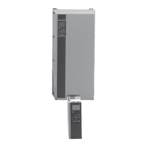
- Page 1 GRUNDFOS PRODUCT GUIDE Grundfos CUE Frequency converters for pump control 60 Hz...
-
Page 2: Table Of Contents
Operating range ............24 IP21/NEMA1 kit ............55 Motor bearing monitoring ..........24 Output filters ..............56 Standstill heating ............24 Grundfos differential pressure sensor, DPI ....59 Ramps ................25 Proportional differential pressure, parabolic ....25 Hmax update ..............26 Further product documentation Differential pressure from two sensors ......26 Start delay after power-up..........26... - Page 3 Mission Grundfos CUE — to successfully develop, produce and sell high-quality pumps and pumping systems worldwide, contributing to a better quality of life and a healthy environment Bjerringbro, Denmark Fresno, California Olathe, Kansas Monterrey, Mexico Allentown, Pennsylvania Oakville, Ontario • One of the 3 largest pump companies in the world •...
-
Page 4: Introduction
Fig. 1 Grundfos CUE solution Built-in E-pump functionality The CUE solution contains the same control functionality as the Grundfos E-pumps and is thus a supplement to the E-pump range. See the table below. All CUE Solutions are available in two enclosure classes: IP21 (NEMA 1) or IP55 (Nema 12). - Page 5 The CUE can be used in both new and existing instal- lations, but the pump and motor should be suitable for use with frequency converters. The table below shows which Grundfos pump types the CUE is designed for. Pump type...
-
Page 6: Features And Benefits
The duty/standby function is used to alternate between known system from Grundfos E-pumps. two pumps. Each pump is connected to a CUE unit. The • Remote operation via external signals, for instance primary task is to start the standby pump if the duty via digital inputs or GENIbus. -
Page 7: Accessories
Features and benefits Grundfos CUE Accessories Grundfos offers a number of accessories for the CUE. MCB 114 sensor input module The MCB 114 is an option offering additional analog inputs for the CUE: • 1 analog input, 4-20 mA • 2 inputs for Pt100/Pt1000 temperature sensors. -
Page 8: Applications
Applications Grundfos CUE Overview applications The CUE is a multi-purpose frequency converter suita- ble for a variety of applications demanding reliable and cost-efficient pump operation. The CUE is used in five main fields of application: Water supply and pressure boosting... -
Page 9: Identification
Identification Grundfos CUE Nameplate The CUE can be identified by means of the nameplate. An example is shown below. Fig. 2 Example of nameplate Text Description CUE (product name) T/C: 202P132... (internal code) Prod.no: Product number: 96754515* Serial number: 123456G123... -
Page 10: Product Range
Product range Grundfos CUE Overview The CUE cabinet sizes are characterised by their enclosures. The table shows the relation between power size (P2), mains supply (V) and enclosure class (IP). It shows the complete range of the CUE. Mains supply and enclosure class... -
Page 11: Functions
Functions Grundfos CUE Overview The table below shows the functions settings offered by the CUE. Setting or reading via: CUE functions GENIbus PC Tool* Operating modes, see page 13 Normal Stop Min. Max. Control modes, see page 14 Open loop... - Page 12 Functions Grundfos CUE Setting or reading via: CUE functions GENIbus PC Tool* Digital inputs, see page 27 Start/stop Min. (Min. curve) Max. (Max. curve) External fault Flow switch Alarm reset Dry running (from external sensor) Accumulated flow (from pulse flow sensor)
-
Page 13: Operating Modes
Functions Grundfos CUE Operating modes These operating modes can be selected with the CUE: • Normal • Stop • Min. • Max. The operating modes can be set without changing the setpoint setting. Normal The pump operates in the control mode selected. See page 14. -
Page 14: Control Modes
Functions Grundfos CUE Control modes The CUE has a built-in PID controller that provides closed-loop control of the value you want to control. The CUE can also be set to open-loop control where the setpoint represents the desired pump speed. - Page 15 Functions Grundfos CUE Open loop, constant curve Constant differential pressure, pump The speed is kept at a set value in the range between The differential pressure of the pump is kept constant, the min. and max. curves. See fig. 4.
- Page 16 Functions Grundfos CUE Constant pressure with stop function Constant level with stop function The outlet pressure is kept constant at high flow rate. The liquid level is kept constant at high flow rate. On/off On/off operation at low flow rate. See fig. 8.
-
Page 17: Setpoints
Functions Grundfos CUE Constant temperature In control mode Open loop, the setpoint is set in% cor- responding to the required speed. The setting range is The liquid temperature is kept constant, independently between the min. and max. curves. of the flow rate. See fig. 12. - Page 18 Functions Grundfos CUE External setpoint influence (default) Inverse external setpoint The actual setpoint is a linear function of the external The actual setpoint is an inverse linear function of the setpoint signal. See fig. 15. external setpoint signal. See fig. 17.
- Page 19 Functions Grundfos CUE External setpoint with stop function The linear function is defined as an interpolation between the points in a table. The table has of up to 8 Setting via PC Tool. points. The actual setpoint with stop is a linear function of the...
-
Page 20: Setting The Direction Of Rotation
Functions Grundfos CUE Setting the direction of rotation Operating hours The value of operating hours is an accumulated value The start-up guide begins the first time the CUE is con- calculated from the pump’s birth and cannot be reset. nected to supply voltage. While going through the start- No additional sensor is required. -
Page 21: Pid Controller
Functions Grundfos CUE PID controller Suggested controller settings The CUE has a built-in PID controller for speed control System/application Heating Cooling of pumps. The factory setting of gain (K ) and integral system system time (T ) can easily be changed in the control panel. -
Page 22: Stop Functions
Functions Grundfos CUE Stop functions Note: The non-return valve must always be installed before the pressure sensor. See figs 23 and 24. Constant pressure with stop function The purpose of the stop function is to stop the pump Diaphragm tank when low or no flow is detected. -
Page 23: Dry-Running Protection
The two pumps use their own local operating mode. For instance, pump 1 can operate in Normal mode, and pump 2 can operate in Max. mode. ® • a Grundfos Liqtec dry-running switch • a pressure switch installed on the suction side of the Control mode pump Both pumps must have the same control mode. -
Page 24: Operating Range
Functions Grundfos CUE Operating range Extended function The bearing temperature is also included in the calcu- The area between the min. and max. speed is the lation. actual operating range of the pump. The extended function requires an MCB 114 sensor... -
Page 25: Ramps
Functions Grundfos CUE Ramps Proportional differential pressure, parabolic The controller incorporates two types of ramp: Setting via PC Tool. • ramp-up and ramp-down (default) • initial and final ramps (setting via PC-Tool). The proportional differential pressure can be selected with one of these flow dependencies: Speed •... -
Page 26: Hmax Update
Functions Grundfos CUE Hmax update Sensor 2 is connected to the sensor input 2 of an MCB 114 sensor input module. Setting via PC Tool. Start delay after power-up This function is used in connection with the control mode Proportional differential pressure. The purpose is Setting via PC Tool. -
Page 27: Limit Exceeded
Functions Grundfos CUE Limit exceeded Digital inputs Setting via PC Tool. As standard, the CUE offers these digital inputs: This is a monitoring function offering information, warn- • one digital input for external start/stop ing or alarm when a low or high limit is exceeded. See •... -
Page 28: Signal Relays
Functions Grundfos CUE Predefined ramps (setting via PC Tool) Analog inputs The ramp-up and ramp-down time can be remote-set As standard, the CUE offers these analog inputs: from the default setting to a predefined setting by • one analog input for external setpoint means of PC Tool. -
Page 29: Mcb 114 Sensor Input Module
The MCB 114 sensor input module offers three addi- RS-485 port must be selected to GENIbus, and the tional analog inputs for the CUE: communication must be set according to the Grundfos • one analog 4-20 mA input for an additional sensor GENIbus standard. -
Page 30: Copy Of Setting
• Make a copy of the setup from the present CUE to the Grundfos Local Control Panel • Make a copy of the setup stored in the Grundfos Lo- cal Control Panel to the CUE Both functions must be used in the correct order to copy a setup from one CUE to another. -
Page 31: Installation
Installation Grundfos CUE Mechanical installation Required free space in front of the CUE Furthermore, there must be sufficient space in front of The CUE cabinet sizes are characterised by their the CUE for opening the door of the CUE. See fig. 37. -
Page 32: Electrical Installation
8 AWG [10 mm Protection against short-circuit, fuses The CUE and the supply system must be protected against short-circuit. Grundfos demands that the fuses mentioned on 48 are used for protection against short-circuit. - Page 33 Installation Grundfos CUE Mains and motor connection Wiring diagram, signal terminals The supply voltage and frequency are marked on the CUE nameplate. Make sure that the CUE is suitable for 0/4-20 mA 4-20 mA Terminals the electricity supply of the installation site.
-
Page 34: Rfi Filters
• motor cable length from the frequency converter-driven motor. • the required reduction of the acoustic noise from the motor. Grundfos offers two types of output filter as accessories for the CUE: • dU/dt filters • sine-wave filters The filters are IP20/NEMA1 enclosure. -
Page 35: Emc-Correct Installation
Installation Grundfos CUE EMC-correct installation Typical shaft Sine-wave Pump type dU/dt filter This section gives guidelines for good practice when power P2 filter installing the CUE. Follow these guidelines to meet EN 0-1000 ft Up to 10 Hp – 61800-3, first environment. - Page 36 Installation Grundfos CUE Fig. 43 Example of stripped cable with screen Fig. 44 Do not twist the screen ends Controller Fig. 45 Example of connection of a 3-conductor bus cable with screen connected at both ends Controller Fig. 46 Example of connection of a 3-conductor bus cable...
-
Page 37: Operation
Operation Grundfos CUE Control panel Start-up guide The control panel is used for local setting of the CUE. Use the start-up guide for the general setting of the The functions available depend on the pump family. CUE including the setting of the correct direction of rotation. -
Page 38: Warning And Alarm List
Operation Grundfos CUE Warning and alarm list Warning The CUE will continue the operation as long as the Status warning is active. The warning remains active until the cause no longer exists. Some warnings may switch to Operat- alarm condition if the warning has been present for a... -
Page 39: Cue Selection
CUE selection Grundfos CUE How to select a CUE The size of the CUE is determined quickly and precisely based on the max. motor current. See fig. 48. The power size, which is the typical shaft power P2, is only an approximate value and cannot be used to select the nominal size of the CUE. -
Page 40: Special Conditions
CUE selection Grundfos CUE Special conditions High ambient temperature If the output current is reduced to 80 % of the nominal Derating must be taken into account when using the output current of the CUE in questions, the ambient CUE in these situations: may be 5 °C higher. -
Page 41: Selection Tables
CUE selection Grundfos CUE Selection tables Mains supply 1 x 200-240 V Rated CUE constant output filter enclosure CUE only Input output pressure* Enclosure conductor Efficiency rating part number dU/dt Sine wave Voltage amps part number (AWG) IP21 91136746 91136789 0.96... - Page 42 CUE selection Grundfos CUE Mains supply 3 x 200-240 V Rated CUE constant output filter enclosure CUE only Input output pressure* Enclosure conductor Efficiency rating part number dU/dt Sine wave Voltage amps part number (AWG) IP21 91136747 91136790 0.95 96754973...
- Page 43 CUE selection Grundfos CUE Mains supply 3 x 440 - 500V Rated CUE constant output filter enclosure CUE only Input output pressure* Enclosure conductor Efficiency rating part number dU/dt Sine wave Voltage amps part number (AWG) IP21 91136762 91136805 0.95...
- Page 44 CUE selection Grundfos CUE Mains supply 3 x 525-600 V Rated CUE constant output filter enclosure CUE only Input output pressure* Enclosure conductor Efficiency rating part number dU/dt Sine wave Voltage amps part number (AWG) IP21 91136781 91136824 0.97 96755040...
-
Page 45: Technical Data
Technical data Grundfos CUE Main dimensions and weight B4, C3, C4 Fig. 50 Enclosures A2 and A3 Fig. 51 Enclosures A5, B1, B2, B3, B4, C1, C2, C3 and C4 Fig. 52 Enclosures D1 and D2 Screw holes [in (mm)]... - Page 46 Technical data Grundfos CUE Screw holes [in (mm)] Height [in (mm)] Width [in (mm)] Depth [in (mm)] Weight Enclosure [lb (kg)] ∅d ∅e 30.31 29.09 14.57 13.15 13.19 13.19 .472 .748 .354 .386 143.3 (770) (739) (370) (334) (335) (335) (12.0)
-
Page 47: Surroundings
Technical data Grundfos CUE Surroundings Terminal tightening torques Relative humidity 5-95 % RH Tightening torque [Nm] Enclosure Minimum ambient temperature at full operation 32° F (0 °C) Mains Motor Ground Relay Minimum ambient temperature at reduced op- 14° F (–10 °C) eration –13°... -
Page 48: Fuses
Technical data Grundfos CUE Fuses Non-UL fuses and conductor cross-section to mains and motor Maximum conductor Typical shaft Maximum Fuse Maximum conductor Typical shaft Maximum Fuse power P2 fuse size type cross-section power P2 fuse size type cross-section [kW] [AWG] (mm... - Page 49 Technical data Grundfos CUE UL fuses and conductor cross-section to mains and motor Fuse type Maximum conductor CUE Output Amps cross-section Bussmann Bussmann Bussmann SIBA Littel Fuse Ferraz-Shawmut Ferraz-Shawmut [Amp (kW)] [AWG] 1 x 200-240 V KTN-R20 – – –...
- Page 50 Technical data Grundfos CUE Fuse type Maximum conductor CUE Output Amps cross-section Bussmann Bussmann Bussmann SIBA Littel Fuse Ferraz-Shawmut Ferraz-Shawmut [Amp (kW)] [AWG] 11 (7.5) KTS-R30 JKS-30 JJS-30 5012406-032 KTN-R30 ATM-R30 A2K-30R 3 x 525-690 V – – – –...
-
Page 51: Inputs And Outputs
Technical data Grundfos CUE Inputs and outputs Signal relays Mains supply (L1, L2, L3) Relay 01, terminal number 1 (C), 2 (NO), 3 (NC) Relay 02, terminal number 4 (C), 5 (NO), 6 (NC) Supply voltage 200-240 V ± 10 %... -
Page 52: Accessories
Kit* 0-580 psi (0-40 bar) 91136173 Kit* 0-870 psi (0-60 bar) 91136174 Grundfos differential pressure sensor option, 0.9 m screened cable 0-8.7 psi (0-0.6 bar) 96611522 0-14.5 psi (0-1.0 bar) 96611523 Pressure connection: 7/16” Including fittings for pressure connection (1/4" - 7/16"), 0-23 psi (0-1.6 bar) -
Page 53: Mcb 114 Sensor Input Module
Accessories Grundfos CUE MCB 114 sensor input module Technical data Relative humidity 5-95% RH 14 to 131° F Ambient temperature during operation (–10 to 55° C) –13 to 158° F Temperature during storage and transportation (–25 to 70° C) Maximum length, signal cable... -
Page 54: Grundfos Local Control Panel, Glcp
Accessories Grundfos CUE Grundfos Local Control Panel, GLCP Remote-mounting option for GLCP GLCP is used for local setting of the CUE. By means of a remote-mounting option, the GLCP can also be moved to the front of a cabinet. The enclosure The CUE unit comes default with a GLCP fitted, but the is IP65. -
Page 55: Floor-Mounting Option
Accessories Grundfos CUE Floor-mounting option IP21/NEMA1 kit By means of a pedestal, the CUE can also be mounted An IP20 enclosure can be upgraded to IP21/NEMA1 on the floor. A pedestal has been designed for that pur- with the IP20/NEMA1 kit. The power terminals (mains pose. -
Page 56: Output Filters
Accessories Grundfos CUE Output filters Grundfos offers two types of output filter as accessories for the CUE: • dU/dt filters • sine-wave filters. The filters are in IP20/NEMA1 enclosure. Fig. 62 Wall-mounted sine-wave filters Use of output filters The table below explains in which cases an output filter is required. - Page 57 Accessories Grundfos CUE Dimensions and weight of output filters Fig. 63 Wall mounting Fig. 64 Floor mounting Height [in (mm)] Width [in (mm)] Depth [in (mm)] Screw holes [in (mm)] Weight Product number Mounting ∅d ∅e [lbs (kg)] Sine-wave filters...
-
Page 58: Grundfos Differential Pressure Sensor, Dpi
Accessories Grundfos CUE Grundfos differential pressure Wiring diagram sensor, DPI Product description A cable (pos. 1) goes through an M12 x 1.5 pg connec- tion. See fig. 65. The sensor housing and parts in contact with the medium are made of Inox DIN W.-Nr. 1.4305 (pos. 3) with composite PA top (pos. -
Page 59: Further Product Documentation
WebCAPS is a Web-based Computer Aided Product Selection program available on www.grundfos.com. WebCAPS contains detailed information on more than 185,000 Grundfos products in more than 20 languages. In WebCAPS, all information is divided into 6 sections: • Catalogue • Literature •... -
Page 60: Wincaps
The section contains replacement data of a wide range of pumps produced by other manufacturers than Grundfos. Based on an easy step-by-step guide, you can compare Grundfos pumps with the one you have installed on your site. When you have specified the installed pump, the guide will suggest a number of Grundfos pumps which can improve both comfort and efficiency. - Page 61 Further product Grundfos CUE documentation...
- Page 62 Further product Grundfos CUE documentation...
- Page 63 Further product Grundfos CUE documentation...
- Page 64 1009 Subject to alterations. Rep. 1108 The name Grundfos, the Grundfos logo, and the payoff Be–Think–Innovate are registered trademarks © 2008, 2009 Grundfos Pumps Corp. owned by Grundfos Management A/S or Grundfos A/S, Denmark. All rights reserved worldwide. GRUNDFOS Pumps Corporation GRUNDFOS Canada Inc.
Need help?
Do you have a question about the CUE Series and is the answer not in the manual?
Questions and answers