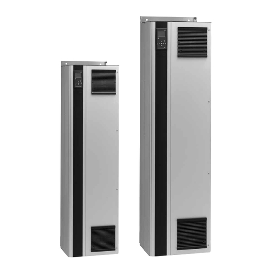
Grundfos CUE Installation And Operating Instructions Manual
110-250 kw
Hide thumbs
Also See for CUE:
- Installation and operating instructions manual (47 pages) ,
- Safety instructions and other important information (26 pages) ,
- Instructions manual (26 pages)
Table of Contents
Advertisement
Advertisement
Table of Contents

Related Manuals for Grundfos CUE


Summary of Contents for Grundfos CUE
- Page 1 GRUNDFOS INSTRUCTIONS CUE, 110-250 kW Installation and operating instructions...
-
Page 2: Table Of Contents
CUE is a series of external frequency converters especially RFI filters designed for pumps. Output filters Thanks to the startup guide in the CUE, the installer can quickly Operating modes set central parameters and put the CUE into operation. Control modes... -
Page 3: References
3.4.1 Reduction at low air pressure • The on/off button of the control panel does not disconnect the CUE from the power supply and must therefore not be used as Warning a safety switch. At altitudes above 2000 m, the PELV requirements •... -
Page 4: Identification
CAUTION: 5.2.1 Lifting the CUE SEE MANUAL / VOIR MANUEL Always lift the CUE using the lifting holes. Use a bar to avoid WARNING: bending the lifting holes. See fig. 2. STORED CHARGE DO NOT TOUCH UNTIL... -
Page 5: Space Requirements And Air Circulation
Min. 225 2. Drill the holes. See fig. 5. 3. Fit the screws at the bottom, but leave loose. Lift the CUE up on the screws. Move the CUE against the wall, and fit the screws at the top. Tighten all four screws. See fig. 2. - Page 6 See the pedestal kit instructions for further Note information. By means of a pedestal (option), the CUE can also be mounted on the floor. 1. Mark the mounting holes on the floor. See fig. 6. 2. Drill the holes.
-
Page 7: Electrical Connection
The circuit breaker is type B. The total leakage current of all the electrical equipment in the installation must be taken into account. The leakage current of the CUE in normal operation can be seen in section 16.7.1 Mains supply (L1, L2, L3). -
Page 8: Connecting The Signal Terminals
6.2.3 Gland plate Cables are connected through the gland plate from the bottom. The gland plate must be fitted to the CUE to ensure the specified protection degree as well as to ensure sufficient cooling. Drill holes in the marked areas. See fig. 10. - Page 9 6.3.2 Wiring diagram, signal terminals Terminals 0/4-20 mA 0-10 V Terminals External setpoint, External setpoint, current input voltage input U: 0-10 V U: 0-10 V I: 0/4-20 mA I: 0/4-20 mA 0/4-20 mA Terminals Two-wire sensor 0/4-20 mA Terminals Three-wire sensor U: 0-10 V U: 0-10 V I: 0/4-20 mA...
- Page 10 6.3.4 Access to signal terminals All terminals for signal cables are located beneath the control panel and can be accessed by opening the door of the CUE. See Fig. 14 Fitting the conductor into the signal terminal fig. 13.
-
Page 11: Connecting The Signal Relays
6.3.7 RS-485 GENIbus network connection 6.5 Connecting the MCB 114 sensor input module One or more CUE units can be connected to a control unit via The MCB 114 is an option offering additional analog inputs for the GENIbus. See the example in fig. 16. -
Page 12: Emc-Correct Installation
Connect the screen to frame at both ends for both motor and signal cables. See fig. 22. If the controller has no cable clamps, connect only the screen to the CUE. See fig. 23. • Avoid unscreened motor and signal cables in electrical cabinets with frequency converters. -
Page 13: Output Filters
Fig. 24 Example of installation without filter Fig. 25 Example of installation with filter. The cable between the CUE and filter must be short Fig. 26 Submersible pump without connection box. Frequency converter and filter installed close to the well Fig. -
Page 14: Operating Modes
7. Operating modes 8.2 Controlled operation (closed loop) The following operating modes are set on the control panel in the Proportional "OPERATION" menu, display 1.2. See section 10.6.2 Operating differential mode (1.2). pressure. The differential Operating mode Description pressure is reduced The pump is running in the control mode at falling flow rate Normal... -
Page 15: Menu Overview
It is also possible to see the latest five warnings and alarms. 3. "STATUS" shows the status of the CUE and the pump. It is not possible to change or set values. 4. "INSTALLATION" gives access to all parameters. Here a... - Page 16 2. STATUS 3. INSTALLATION 2.10 3.12 3.24 2.11 3.13 3.25 2.12 3.14 2.13 3.3A 2.14 3.16 3.17 2.16 3.18 2.17 3.19 3.20 3.21 3.10 3.22 3.11 3.23...
-
Page 17: Setting By Means Of The Control Panel
The editing buttons of the control panel can be set to these condition, pump operation is not possible. values: • Active The control panel is used for local setting of the CUE. The functions available depend on the pump family connected to the • Not active. CUE. -
Page 18: Back To Factory Settings
Have nameplate data for motor, pump and CUE at hand. Value field Use the startup guide for the general setting of the CUE including the setting of the correct direction of rotation. The startup guide is started the first time when the CUE is connected to the power supply. - Page 19 Select "Other" if the pump family is not on the list. selected. 10.4.5 Rated motor power (4/16) Max. current will be limited to the value on the CUE nameplate, even if it is set to a higher value during setup. 10.4.8 Speed (7/16) Set the rated motor power, P2, according to the motor nameplate: •...
- Page 20 The possible settings and the factory setting depend on the pump • Other. family. The CUE will give an alarm if the control mode selected requires Constant pressure: Constant flow rate: a sensor and no sensor has been installed. To continue the •...
- Page 21 It is possible to interrupt the test and return to the previous display. See the installation and operating instructions of the pump. The general setting of the CUE is now completed, and the startup guide is ready for setting the direction of rotation: •...
- Page 22 State if the direction of rotation is correct. 10.4.17 Setpoint (8/16) • Yes • No Set the setpoint according to the control mode and sensor selected. The correct direction of The direction of rotation is not rotation has now been set. correct.
-
Page 23: General
Write down the pressure and/or flow rate, and press OK to The menu makes it possible to return to the startup guide, which continue the manual test with the opposite direction of is usually only used during the first startup of the CUE. rotation. 10.5.1 Return to startup guide (0.1) The pump starts after 10 seconds. -
Page 24: Operation
A warning will activate a warning indication in CUE, but the pump will not change operating or control mode. It is possible to copy the settings of a CUE and reuse them in Alarm (1.3) another one. -
Page 25: Status
This display shows the actual value controlled. in the warning log. "Warning log 1" shows the latest fault, If no sensor is connected to the CUE, "-" will appear in the "Warning log 2" shows the latest fault but one, etc. - Page 26 The display shows the measuring point and the actual value measured by a Pt100/Pt1000 temperature sensor 1 connected to the MCB 114. The measuring point is selected in display 3.21. If no sensor is connected to the CUE, "-" will appear in the display.
-
Page 27: Installation
• Constant pressure the MCB 114. The measuring point is selected in display 3.22. • Constant differential pressure If no sensor is connected to the CUE, "-" will appear in the display. • Proportional differential pressure • Constant flow rate 10.7.14 Flow rate (2.14) - Page 28 The table below shows the suggested controller settings: How to set the PI controller For most applications, the factory setting of the controller constants K and T will ensure optimum pump operation. However, in some applications an adjustment of the controller System/application Heating Cooling...
- Page 29 Note section 10.6.3 Fault indications. 10.8.5 Buttons on the CUE (3.6) The digital inputs of the CUE (terminal 19, 32 and 33) can be set individually to different functions. Select one of the following functions: • Min. (min. curve) The editing buttons (+, -, On/Off, OK) on the control panel can be •...
- Page 30 This requires the use of an accessory, such as: • External sensor ® • a Grundfos Liqtec dry-running switch • Limit 1 exceeded • a pressure switch installed on the suction side of a pump •...
- Page 31 1. Low-flow detection function Diaphragm tank The pump will check the flow regularly by reducing the speed for a short time. If there is no or only a small change in pressure, this Pressure sensor means that there is low flow. The speed will be increased until the stop pressure (actual setpoint + 0.5 x ΔH) is reached and the pump will stop after a few seconds.
- Page 32 10.8.12 Constant level with stop function (3.14) 2. Low-flow detection with flow switch When the digital input is activated because of low flow, the speed will be increased until the stop level (actual setpoint - 0.5 x ΔH) is reached, and the pump will stop. When the level has reached the start level, the pump will start again.
- Page 33 GENIbus. The duty/standby function applies to two pumps connected in parallel and controlled via GENIbus. Each pump must be connected to its own CUE and sensor. The primary targets of the function is the following: • To start the standby pump if the duty pump is stopped due to an alarm.
- Page 34 Select the function of a Pt100/Pt1000 temperature sensor 1 • Not active. connected to an MCB 114: When the function is set to "Active", the CUE will give a warning • D-end bearing when the motor bearings are due to be relubricated or replaced.
-
Page 35: Setting By Means Of Pc Tool E-Products
Set the time for each of the two ramps, ramp-up and ramp-down: condition, pump operation is not possible. • Factory setting: The CUE can be controlled in various ways at the same time. If Depending on power size. two or more operating modes are active at the same time, the •... -
Page 36: External Control Signals
"Controlled" control mode Example: At a sensor min. value of 0 bar, a setpoint set via the CUE menu of 3 bar and an external setpoint of 80 %, the actual setpoint will be as follows: Actual (setpoint set via the CUE menu - sensor min.) -
Page 37: Genibus Signal
In "Proportional differential pressure" control mode, the actual 15.1 Warning and alarm list setpoint can be set externally within the range from 25 % of maximum head to the setpoint set via the CUE menu. See fig. 40. Status Setpoint... -
Page 38: Resetting Of Alarms
15.2 Resetting of alarms In case of a fault or malfunction of the CUE, check the alarm list in the "OPERATION" menu. The latest five alarms and latest five warnings can be found in the log menus. Contact a Grundfos technician if an alarm occurs repeatedly. -
Page 39: Technical Data
16. Technical data 16.1 Enclosure Example: Read from the nameplate: The individual CUE cabinet sizes are characterised by their enclosures. The table shows the relationship of enclosure class • Supply voltage = 3 x 380-500 V. and enclosure type. •... -
Page 40: Surroundings
Maximum conductor Typical shaft Maximum Fuse power P2 fuse size type cross-section The CUE comes in a packaging which is not suitable Note [kW] for outdoor storage. 3 x 380-500 V 16.4 Terminal torques 2 x 70 2 x 70... -
Page 41: Inputs And Outputs
24 VDC 10 mA Minimum terminal load 24 VAC 20 mA The sound pressure of the CUE is measured at a distance of 1 m from the unit. IEC 60947, parts 4 and 5. The sound pressure level of a motor controlled by a frequency... - Page 42 Declaration of conformity GB: EU declaration of conformity We, Grundfos, declare under our sole responsibility that the product CUE, to which the declaration below relates, is in conformity with the Council Directives listed below on the approximation of the laws of the EU member states.
- Page 43 Unit 1, Ground floor Telefax: +64-9-415 3250 Turkey «Порт» Siu Wai Industrial Centre GRUNDFOS POMPA San. ve Tic. Ltd. Sti. Тел.: +7 (375 17) 286 39 72/73 29-33 Wing Hong Street & Norway Gebze Organize Sanayi Bölgesi Факс: +7 (375 17) 286 39 71...
- Page 44 96783675 0916 ECM: 1187342 www.grundfos.com...
Need help?
Do you have a question about the CUE and is the answer not in the manual?
Questions and answers