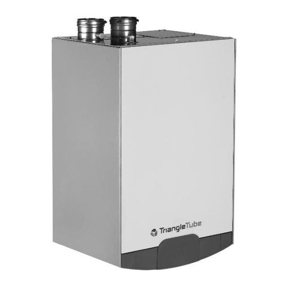
TriangleTube prestige Solo 399 Manual
Concentric vent/air system supplement
Hide thumbs
Also See for prestige Solo 399:
- Installation and maintenance manual (89 pages) ,
- Installation & maintenance manual (100 pages) ,
- Instructions (5 pages)
Table of Contents
Advertisement
Quick Links
prestige
Solo 399
Concentric Vent/Air System Supplement
This document is intended to be used by a qualified heating contractor or service
WARNING
technician. Read all instructions within this document and within the PRESTIGE
Boiler Installation and Maintenance Manual, before proceeding with the installa-
tion. It is recommended to follow the procedures in the steps given, skipping or
missing procedural steps could result in severe personal injury, death or sub-
stantial property damage.
Installation of this boiler must comply with local requirements and codes and
NOTICE
with the National Fuel Gas Code NFPA 54, ANSI Z223.1 for installations within the
U.S. For installations in Canada the installation must comply with CSA B149.1 or
B149.2
2008-37 Prestige Conc_AIrVentSup.
Date: 3/16/09
Advertisement
Table of Contents

Subscribe to Our Youtube Channel
Summary of Contents for TriangleTube prestige Solo 399
- Page 1 prestige Solo 399 Concentric Vent/Air System Supplement This document is intended to be used by a qualified heating contractor or service WARNING technician. Read all instructions within this document and within the PRESTIGE Boiler Installation and Maintenance Manual, before proceeding with the installa- tion.
-
Page 2: Table Of Contents
Table of Contents PRODUCT AND SAFETY INFORMATION Definitions........... 1 SECTION I - PRE-INSTALLATION ITEMS General Requirements. -
Page 3: Product And Safety Information
Product & Safety Information Definitions The following terms are used throughout this manual to bring attention to the presence of potential hazards or to important information concerning the product. NOTICE WARNING Indicates a potentially hazardous situation Indicates special instructions on installa- which, if ignored, can result in death, seri- tion, operation or maintenance, which are ous injury or substantial property damage. -
Page 4: Section I - Pre-Installation Items
Pre-Installation Items SECTION I - Pre-Installation Items Do not connect more than a single boiler into the vent/air system. General Requirements All penetrations of the vent/air system through ceil- Installation of the vent/air system must comply with ings, floors or walls must be properly fire stopped. local codes and requirements and with the National Check with local codes and requirements regarding Fuel Gas Code NFPA 54, ANSI Z223.1 for installa-... -
Page 5: Assembled Vent/Air System Kit Dimensions
Pre-Installation Items 35” 9 1/2” Face of Wall 10” Fig. 2: Assembled Vent/Air System Kit Dimensions Fire Stop Support Clamp Hanging PSVSUP01 Elbow - 45º Elbow - 90º PSVCLP01 PSVELB02 PSVELB01 Inner Pipe Gasket Not Shown PSVGSK01 Adjustable Length Pipe - 40” Fixed (12.4”... -
Page 6: Section Ii - Vent/Air System Installation
Vent/Air System Installation SECTION II - Vent/Air System Maintain the following clearances to the termi- Installation nation Vent/Air System Clearance Requirements a. At least 3 feet from adjacent walls b. No closer than 3 feet below roof overhangs The vent/air system may maintain zero clearance to c. -
Page 7: Boiler Vent/Air System Adapter
Vent/Air System Installation Vent/Air Adapter 9 1/2” Face of Wall Boiler Air Boiler Vent Inlet Adapter Outlet Adapter 12” Min. Air Intake Adapter Band Clamps Fig. 6: Assembly of Vent/Air Adapter Grade/Anticipated Vent/Air System Joint Assembly Snow Line 1. When installing the vent system, the female end Fig. -
Page 8: Termination Installation
Vent/Air System Installation WARNING WARNING It is very important that the clamp be prop- Do not over tighten the self-drilling screws into the sections. Use a low torque screw erly installed. Failure to properly connect drive to prevent stripping out the holes. If a the vent components could lead to vent fail- hole becomes stripped due to over tightening, ure and can result in death, serious injury or... -
Page 9: Cutting Termination Fitting To Length
Vent/Air System Installation 5. The gaps between the outer pipe of the termina- Adjustable Length Vent/Air System Pipe tion fitting and the support plates must be sealed with a high quality silicone caulk. Also apply the silicone caulk along the outer edge of the WARNING support plates sealing the plates to the wall. -
Page 10: Fire Stop Support Plate
Vent/Air System Installation Fire Stop Support Plate Multiple Vent/Air System Terminations For multiple boiler vent/air system installations The Fire Stop Support Plate must be used when the maintain a minimum of 12 inches from centerlines as vent/air system piping passing through any floors, shown in Fig. -
Page 11: Section Iii - Maintenance Procedures
Maintenance Procedures SECTION III - Maintenance Procedures Inspect Vent/Air System Visually inspect the vent/air system annually for blockage, deterioration or leakage. Immediately repair any joints that show signs of deterioration or leakage with the boiler turned off. WARNING Failure to inspect the vent/air system and have any conditions repaired can result in severe personal injury or death. - Page 12 Specially designed built-in flow restrictor to assure maximum heat exchange Compact and light weight Available in 5 sizes that can accommodate any size pool or spa Member of Freeway Center - 1 Triangle Lane Blackwood, NJ 08012 Tel: (856) 228 8881 - Fax: (856) 228 3584 E-mail: Sales@triangletube.com Group...


Need help?
Do you have a question about the prestige Solo 399 and is the answer not in the manual?
Questions and answers